Note: Descriptions are shown in the official language in which they were submitted.
- 1 -
PIPE LAP JOINT WITH IMPROVED COLLAPSIBLE SEALING ZONE
FIELD OF THE INVENTION
This invention relates to pipe couplings; more
particularly it relates to a pipe lap joint especially adapted for
use in vehicle exhaust systems.
BACKGRODND OF THE INVENTION
In certain applications such as vehicle exhaust systems
it is desired to provide a pipe joint with high pull-apart
strength and with a good fluid seal between the pipes . It has
become increasingly important, especially in connection with
vehicle exhaust systems, to achieve greater reliability and
uniformity in providing pipe couplings with a good fluid seal.
In the prior art, a pipe coupling which provides high
strength and a good fluid seal has been provided by a pipe lap
joint having a collapsible sealing zone and a band clamp as
disclosed and claimed in Cassel U.S. Patent 4,629,226 granted
December 16, 1986. In the lap joint of that patent, a collapsible
sealing zone is provided in the outer pipe by at least one pair of
intersecting end-to-end slots which afford relief for
circumferential contraction of the sealing zone within the overlap
region of the pipe ends. A clamping band is disposed around the
outside pipe and covers the inboard slot. The clamping band is
tightened around the outside pipe to clamp the pipes together and
x ';
P-315 (BKS) - 2 -
to collapse the sealing zone of the outer pipe into
close fitting engagement with the inner pipe and thereby
cause sealing engagement of the outer pipe with the
inner pipe and with the band. The intersecting slots
comprise an outboard slot and an inboard slot. The
outboard slot has sidewalls extending inwardly from the
end of the outside pipe and terminating in a transverse
inner end wall within the overlap region of the pipes.
The inboard slot is circumferentially offset from the
outboard slot with sidewalls extending axially inwardly
from an outer end wall. The adjacent sidewalls of the
slots are in substantial alignment with each other and
the end walls are in substantial alignment with each
other. When the overlap region of the outer pipe is
collapsed into close fitting engagement with the inner
pipe, the end walls of the slots are moved into
engagement with each other and thereby isolate the slots
from each other and provide a seal.
The lap joint of the aforementioned U.S.
Patent 4,629,226 utilizes a pair of slots which
intersect each other at adjacent corners with the outer
pipe in an uncollapsed state. The inner pipe and outer
pipe walls are telescoped together in a loose fit to
form the lap joint. The manufacturing tolerances of the
pipe diameters result in a large percentage of the mated
pipes having a sufficiently loose fit that the outer
pipe is collapsed sufficiently by the band clamp that
the end walls of the slots are moved into engagement
with each other to isolate the inboard and outboard
slots. However, there is some small percentage of
mating pipes in which the initial fit is so close that
tightening of the band clamp causes very little collapse
of the outer pipe before it is in close fitting
engagement with the inner pipe and there is insufficient
P-315 (BKS) - 3 -
displacement to cause the edge-to-edge engagement of the
end walls of the slots which is necessary to provide
isolation between the two slots. This may lead to
undesirable leakage in some of the pipe joints.
In the earlier prior art, it was known to use
a collapsible sealing zone at the free end of the outer
pipe which is collapsed into sealing engagement with the
inner pipe by a clamping band. A pipe lap joint of this
10 type is disclosed in Wagner et al. U.S. Patent 4,113,289
granted September 12, 1978. The collapsible sealing
zone in the Wagner et al. patent comprises several sets
of slots which are disposed circumferentially around the
end of the outer pipe. In each-set of slots there is an
15 open slot which extends inwardly from the end of the
pipe and an adjacent closed slot, i. e. one which does
not extend to the end of the pipe. The difficulty with
this sealing zone is that the slot structure exhibits a
high resistance to collapsing and accommodates a
20 relatively small amount of reduction in the
circumference of the pipe at each set of slots.
A lap joint of the type using a collapsible
sealing zone is also disclosed in Cassel U.S. Patent
25 4,056,273. In the joint of this patent, a collapsible
sealing ring forms an extension of the outer pipe but is
separate from it. The sealing ring is split so as to
form a tongue on each free end with the tongues having
complementary ramp surfaces in engagement with each
30 other and which slide relative to each other when the
ring is contracted or collapsed. This sealing ring
provides a good seal but the structure is not adapted to
a sealing ring which is integral with the pipe end.
P-315 (BKS) - 4 -
A general object of this invention is to
overcome certain disadvantages of the prior art and to
provide a pipe lap joint with an improved sealing zone.
SUMMARY OF THE INVENTION
In accordance with this invention, a pipe lap
joint is provided which exhibits improved fluid sealing
between the parts despite dimensional variations thereof
within allowable manufacturing tolerances. The pipe lap
joint also exhibits high pull-apart strength and is
economical to manufacture.
Further, in accordance with this invention,
improved fluid sealing properties are provided in a pipe
lap joint of the type in which the overlap region of the
outside pipe comprises a collapsible sealing zone with
at least one pair of end-to-end relief slots which.
accommodate circumferential contraction or collapsing of
the sealing zone by a clamping band around the outside
pipe. In accordance with the invention, a fluid seal is
maintained in a pipe joint when tightening of the clamp
on the outer pipe around the sealing zone produces tight
sealing engagement with the inner pipe regardless of
whether there is any substantial contraction of the
slots. This is achieved by means of non-intersecting
slots which are arranged in such manner as to provide a
bridging segment of the pipe wall between adjacent ends
of the slots. Thus, the first and second slots are
isolated from each other when the frangible bridging
segment is either only slightly deformed or when it is
completely fractured by collapse of the overlap region
of the outer pipe.
P-3l5 (BKS) - 5 - -
Further, in accordance with the invention, the
adjacent sidewalls of the slots are circumferentially
offset from each other and are connected together by a
frangible bridging segment of the wall of the outside
pipe.
Further, in accordance with the invention, the
adjacent end walls of the slots are axially offset from
each other and are connected together by said frangible
ZO bridging segment of the wall of the outside pipe.
Preferably, the frangible bridging segment of the wall
is generally in the shape of a cone with the base of a
cone disposed on the outside diameter of the pipe and
the apex of the cone disposed on the inside diameter of
the pipe.
Further, in accordance with this invention,
the collapsing of the outer pipe at the sealing zone by
the clamping band is facilitated by providing increased
leverage in the application of the clamping force. This
is achieved by making the inboard slot substantially
longer than the outboard slot; preferably, the length of
the outboard slot is minimized to the extent practicable
for mass production of the pipe ends. This permits the
inboard slot to be maximized within the width of the
sealing zone under the clamp band.
Further, in accordance with this invention,
the inboard slot includes transverse slot portions
extending circumferentially outward around the outer
pipe from the inner end of the inboard slot and giving
the inboard slot a "T"-shape. The transverse slot
portions allow both the inboard and the outboard slots
to close together more evenly along their lengths and
allows for improved sealing - particularly in
-
applications where the outer pipe inside diameter is significantly
larger than the inner pipe outside diameter.
Another aspect of the invention pertains to a punch and
die set for punching first and second slots in the wall of a pipe
near one end of the pipe, the first slot having first and second
sidewalls extending axially inwardly from the end of the pipe and
terminating in an inner end wall and the second slot being spaced
inwardly from the end of the pipe and being circumferentially
offset from the first slot and having first and second sidewalls
extending axially inwardly from an outer end wall. The die is a
horn die having a cylindrical section provided with a pair of die
cavities corresponding to the first and second slots, respectively
and having an annular abutment member, the die being adapted to
receive a pipe disposed over the cylindrical section with the
inside diameter of the pipe seated thereon and the end of the pipe
in engagement with the abutment member. The pipe end defines a
plane which is approximately perpendicular to the axis of the pipe
subject to a predetermined maximum out-of-square tolerance. The
first die cavity extends axially of the die and has a first end
wall in axial alignment with the annular abutment member and has
a second end wall at a distance from the first end wall
substantially equal to the sum of the predetermined maximum out-
of-square tolerance plus substantially five times the wall
thickness of said pipe. The second die cavity extending axially
of the die and is circumferentially offset from the first die
cavity and has first and second end walls, the second end wall of
the first die cavity being adjacent the first end wall of the
second die cavity. The second die cavity has a greater axial
length than that of the first die cavity and the punch has a pair
of punch faces mating with the first and second die cavities,
respectively. Thus, the punch and die set is operative to form
the first slot in the pipe with a length of at least about five
times the wall thickness of the pipe regardless of the angular
orientation of the pipe on the horn die.
A complete understanding of this invention may be
obtained from the detailed description that follows taken with the
accompanying drawings.
- A818 12
DESCRIPTION OF THE DRAWINGS
FIGURE 1 is an exploded view of the lap joint of this
invention showing the parts before they are assembled;
FIGURE 2 shows the lap joint of this invention with the
parts assembled and after the joint has been tightened;
FIGURE 3 is a view taken on lines 3 - 3 of FIGURE 2;
FIGURE 4 is a view taken on lines 4 - 4 of FIGURE 2;
FIGURE 5 is a diagram of the punch and die for forming
the slots of FIGURE 1;
FIGURE 6 is a diagram of the die of FIGURE 5 with a pipe
end disposed over the die;
FIGURE 7 is a magnified view of the slots of FIGURE 1
before the outer pipe is collapsed;
FIGURE 7A is a view taken on lines 7A - 7A of Figure 7;
..
P-315 (BKS) - 7 -
FIGURE 8 is a magnified view of the slots of
FIGURE 2 after the outer pipe is collapsed; and
FIGURE 9 shows a second embodiment of the
invention in a magnified view of the slots before the
outer pipe is collapsed;
FIGURE 10 shows the second embodiment in a
magnified view of the slots after the outer pipe is
collapsed;
FIGURE 11 shows a third embodiment of the
invention in a magnified view of the slots before the
outer pipe is collapsed; and
FIGURE 12 shows the third embodiment in a
magnified view of the slots after the outer pipe is
collapsed.
BEST MODE FOR CARRYING OUT THE INVENTION
Referring now to the drawings, there are shown
illustrative embodiments of the invention in a pipe Iap
joint which is especially adapted for use in vehicle
exhaust systems. It will be appreciated as the
description proceeds that the invention is useful in
other embodiments and other applications.
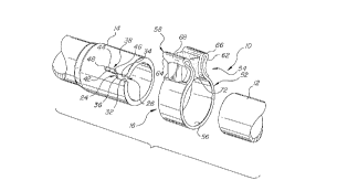
A first embodiment of the invention will be
described with reference to Figures 1 through 8. As
shown in the drawings, the pipe joint 10 of this
invention comprises, in general, inside and outside
pipes 12 and 14, respectively, in a telescoping
relationship with a band clamp 16 for holding the pipes
together. The outside pipe 14 has a lap portion which
P-315 (BKS) _ g _
extends over the inside pipe 12 to provide an overlap
region 18 (Figure 3) of the pipes. In order to provide
a fluid seal between the inside and outside pipes, a
radially collapsible sealing zone 22 is provided on the
outside pipe 14 in the overlap region 18. The
collapsible sealing zone 22 will be described in detail
presently.
The sealing zone 22 comprises a ring shaped
portion of the free end of the outside pipe 14. It is
adapted to be contracted or collapsed in the radial
direction by the clamp 16 so that the sealing zone 22 is
in close fitting engagement with the inside pipe 12.
For this purpose, the sealing zone 22 is provided with
a pair of non-intersecting slots 24 disposed in an
offset end-to-end relationship. In the illustrative
embodiment, only a single pair of intersecting slots is
used. However, in certain embodiments it may be
desirable to use two or more pairs of slots, with the
pairs spaced circumferentially around the pipe.
The pair of non-intersecting slots 24 is shown
in Figure 1 before the sealing zone 22 is collapsed by
the force of the clamp 16. The pair of non-intersecting
slots 24 comprises an outboard slot 26 which is bounded
by a pair of sidewalls 32 ;and 34 extending inwardly from
the end of the outside pipe and terminating in a
transverse inner end wall 36 within the overlap region
18. The sidewalls 32 and 34 are substantially parallel
3 0 to each other and to the axis of the pipe 14 whereas the
inner or inboard end wall 36 extends obliquely of the
sidewalls and the pipe axis at a small angle of
inclination from perpendicularity. The inboard slot 38
is bounded by a pair of sidewalls 42 and 44 extending
axially inwardly from an outer or outboard end wall 46
P-315 (BKS) - 9 -
thereof to an inner or inboard end wall 48. The end
wall 46 extends obliquely of the sidewalls 42 and 44
with an inclination substantially the same as that of
end wall 36. It is noted that the end walls 36 and 46
are both inclined at a small counterclockwise angle, as
viewed in Figure 7, of about four degreesfrom
perpendicularity to the pipe axis. It will be
appreciated, as the description proceeds, that as an
alternative the inclination could be clockwise instead
of counterclockwise. The end wall 36 of slot 26 and the
end wall 46 of slot 38 are axially offset from each
other by a small distance (see Figure 7). The adjacent
sidewalls, namely sidewall 34 and sidewall 42, are
circumferentially offset from each other by a small
distance. The slot 26 and the slot 38 are thus isolated
from each other, by an interposed portion of the wall of
the outer pipe. In the region of closest proximity of
the slots, a small bridging segment 40 of the pipe
wall, integral with the pipe wall, forms a bridge between
the corner formed by end wall 36 and sidewall 34 and the
corner formed by end wall 46 and sidewall 42. These
corners are attached to each other by the bridging
segment 40 of the pipe wall as a result of the slot
forming operation which will be described presently.
The slots 26 and 38 are formed in the pipe 14
by a punching operation with a punch having two punch
segments A and B which coact with a horn die C having
two die cavities D and E. As shown in Figures 5 and 6,
the die is disposed inside the pipe and the punch is
outside the pipe; it will be appreciated, however, that
the punch and die locations could be reversed. The die
C is provided with an annular shoulder C' which serves
as an abutment for positioning the pipe when it is
loaded into the die. The die cavity D is located so
P-315 (BKS) - 10 - -
that its outboard end is aligned with the abutment
surface of the shoulder C'. The punch face is shown in
outline form in Figure 5 wherein the "footprint" of the
punch on the outside diameter of the pipe is represented
by the cross-hatched areas. The punch segments are
mounted for movement in unison to punch the slots in a
single stroke.
In the illustrative embodiment, the inside
pipe 12 has a nominal outside diameter of 1 3/4 inches
and an end portion of the outer pipe 14 is expanded to
form a loose f it over the inside pipe. The wall
thickness of the pipes is nominally 0.048 inches or 1.22
mm. The punch dimensions shown in Figures 5 and 7 for
the illustrative embodiment are as follows: a = 4.23
mm; b = 8.43 mm; c = 9.4 mm; d = 29.8 mm; r = 2.12 mm;
f = 4 degrees; x = 0.10 mm; and y = 0.20 mm. The die is
-- constructed to mate with the punch in accordance with
conventional practice. As a result, the punching
operation causes the punch-out material to break away
from the pipe wall around the periphery of the slots so
that the slots are slightly wider and longer on the die-
side of the pipe wall than on the punch-side, as shown
by the dashed lines in Figure 7.
The punch segments A and B are spaced apart at
their adjacent corners by a small distance whereas the
corresponding die cavities have substantially a point
contact at point P. This arrangement allows the
formation of the bridging segment 40 in the wall of the
pipe. It is noted that the bridging segment between the
slots, as punched, has a cross-sectional area which
diminishes from the punch-side of the pipe to the die-
side. The bridging segment, as shown in Figure 7A, is
cone-shaped with the base of the cone on the punch-side
P-315 (BKS) - 11 -
of the pipe and the apex of the cone on the die-side of
the pipe. As a result, the adjacent corners of the
slots are substantially touching each other at the die-
side of the pipe and are spaced apart at the punch-side.
In order to facilitate the collapsing of the
outer pipe in the sealing zone 22, it is desirable to
maximize the effective leverage of the clamp 16. This
is especially desirable in pipe couplings in which the
outer pipe is of thick wall construction. For this
purpose, in accordance with this invention, the axial
length of the inboard slot 38 is maximized and the axial
length of the outboard slot 26 is minimized. In the
clamping arrangement, the end wall 48 of the inboard
slot acts as a fulcrum point and the lever arm on which
the clamp acts extends from the wall 48 to the outboard
edge of the clamp. However, the axial location of the
bridging segment 40, which exerts a significant
resistance to collapsing of the outer pipe, influences,
to a large extent, the amount of force which must be
applied by the clamp. The bridging segment 40 must be
located within the sealing zone 22, i.e. inboard of the
outboard edge of the clamp 16. To make sure that this
location is obtained for pipe ends that are not "square"
(i.e., not perpendicular to the pipe axis), the outboard
slot must have a certain minimum length in a pipe end
that is square.
In order to minimize the length of the
outboard slot 26 in a pipe punching operation due regard
must be given to (1) the allowable pipe end out-of-
square tolerance and (2) the minimum inset of the
bridging segment 40 from the end of the pipe. The
minimum inset is the minimum spacing of segment 40 from
the end of the pipe which will provide a satisfactory
P-315 (BKS) - 12 - w
isolation of the inboard slot 38 by the segment 40 from
the end of the pipe. Typically, the manufacturing
tolerances allow the plane of the pipe end to deviate
from perpendicularity to the pipe axis by a specified
maximum tolerance. This produces an out-of-square pipe
end with diametrically opposite points, at the longest
and shortest parts of the pipe which are axially offset
by a distance depending upon the tolerance. The
tolerance may be expressed in terms of a percentage, for
example ten percent, of the outside diameter of the pipe
as the maximum allowable offset distance. In the
description that follows, the offset distance which
results in a pipe end with the limiting or maximum value
of tolerance will be referred to as the "maximum
offset".
The pipe end out-of-square tolerance is
accounted for as follows. An outer pipe 14 having an
out-of-square pipe end is illustrated in Figure 6. The
die cavity D must have an axial length greater than the
maximum offset; otherwise, the punch would not engage
the pipe end of a pipe having the maximum offset which
is loaded into the die in an angular position with the
shortest part of the pipe disposed over the die cavity
D.
. The minimum inset of the bridging segment 40
is a function of the wall thickness of the pipe. To
provide a reliable seal at the juncture of the outboard
and inboard slots after collapsing of the outer pipe,
the bridging segment must be spaced from the end of the
pipe by a distance of at least about five times the wall
thickness of the pipe.
P-315 (BKS) - 13 -
The considerations of maximum offset and
minimum inset result in an outboard slot, in a given
pipe, having a length which ranges from a minimum value
equal to about five times the pipe wall thickness to a
maximum value equal to the sum of the maximum offset
plus five times the wall thickness. The maximum value
will occur in a pipe having a square end. The minimum
value will occur in a pipe having a maximum out-of-
square tolerance which was angularly positioned on the
horn die with the shortest part of the pipe opposite the
punch segment for the outboard slot. Thus, the minimum
acceptable length of outboard slot will be obtained in
each of a large number of pipe ends even though each
pipe end has a different out-of-square value which is
within the allowable tolerance. The minimum length
outboard slot provides the maximum leverage for the
clamping of the lap joint.
The preferred clamp for use with the invention
will be described with reference to Figures 1, 2 and 3.
The clamp 16 comprises a clamping band 52 which is
disposed around the outer pipe 14 over the sealing zone
22. In particular, the clamping band 52, for sealing
purposes, must cover the inboard slot 38 and cover the
juncture of the end walls 36 and 46. The clamping band
52 is provided with a tightening means 54. The clamping
band 52 is, for the most part, circular or roundish in
cross-section. It has a roundish sector 56 adapted to
fit around the sealing zone 22 on pipe 14 and a channel-
shaped sector 58 which comprises a pair of sidewalls 62
and 64 extending radially outwardly from the roundish
sector. The clamping band 52 is made of a single piece
of sheet metal and each free end thereof is folded back
on itself to form a double layer. Thus, the sidewalls
62 and 64 are of double thickness and terminate at their
P-315 (BKS) - 14 -
outer ends in respective loops or bights 66 and 68. The
bights 66 and 68 serve as retaining members for holding
the sidewalls in place when the tightening means 54 is
tightened, as will be described subsequently.
The clamping band 52 is tightened around the
pipe 14 by the tightening means 54. The tightening
means comprises a reaction member or spline 72 which is
disposed within the channel-shaped sector 58 and which
is adapted to seat upon the outer surface of the sealing
zone 22 of pipe 14. For this purpose, the spline has an
inner surface of arcuate configuration conforming to the
pipe 14. The spline 72 is provided with a pair of
oppositely facing concave surfaces 74 and 76. The
tightening means includes a bolt 78 and a nut 82. It
also includes a spacer 84 disposed outside the sidewall
62 and having a convex surface which is opposite the
concave surface 74 of the spline 72. The bolt 78 has a
head 81 with a convex surface which is disposed outside
the sidewall 64 opposite the concave surface 76 on the
spline 72. ~ The bolt extends through holes in the
sidewalls 74 and 76, the spline 72 and the spacer 84.
When the pipe j oint 10 is assembled and the
nut 82 is tightened on the bolt 78, the relationship of
the parts is as shown in Figures 2 and 4. It will be
understood that, before the nut and bolt are tightened,
the sidewalls 62 and 64 of the channel-shaped sector 58
are not seated against the spline 72. When the nut 82
is tightened, the bolt head 81 and the spacer 84 are
drawn together and press the sidewalls 62 and 64 into
seating engagement with the spline 72. As a result of
this tightening action, the roundish sector 56 is
stretched around the sealing zone 22 of the pipe 14 in
tight engagement therewith. This tightening action of
P-315 (BKS) - 15 -
the clamp 16 exerts sufficient force on the sealing zone
22 to collapse the sealing zone~by partially closing the
slots 26 anc? 38 in the manner described below.
In making a lap joint of two pipes 12 and 14
which have a tight fit, there is very little room for
collapsing of the outer pipe by tightening the clamp 54.
This can happen in some pipe joints because of the
manufacturing tolerances on the pipe sizes. In this
case, tightening of the clamp 54 does result in
tightening of the outer pipe 14 into close fitting
engagement with the inner pipe 12 throughout the sealing
band 22. However, there is very little displacement of
the wall of pipe 14. Consequently, the slots 26 and 38
are narrowed only a small amount and the bridging
segment 40 is somewhat stretched or torn but not broken
or fractured into two separate parts. Thus, the slots
38 and 26 remain isolated from each other by the
bridging segment and a good fluid seal of a joint is
provided. On the other hand, when the mating pipes 12
and 14 have a looser fit because of the happenstance of
manufacturing tolerances, a different action takes
places upon tightening of the clamp 54. In the case
where there is sufficient clearance between the pipes,
the tightening of the clamp 54 will displace the metal
of the outer pipe 14 in the region of the sealing zone
22 sufficiently that the bridging segment 40 will be
fractured into two parts as shown in Figure 8. As a
result, the collapsing movement of the pipe wall will
reduce the width of the slots 26 and 38. This causes
the end walls 36 and 46 to slide against each other with
continuous sealing engagement therebetween as the clamp
is tightened. Due to the small oblique angle of the end
walls 36 and 46 relative to the pipe axis, tight
engagement therebetween is maintained. Accordingly, the
P-315 (BKS) - 16 - -
slots 26 and 38 remain substantially isolated from each
other and a good fluid seal of the joint is provided.
Thus, the sealing zone 22 is radially
collapsed into sealing engagement with the inside pipe
12 and the clamp 16 is in sewing engagement with the
sealing zone over the inboard slot 38. The engagement
of the end walls 36 and 46 of the slots closes the path
between the slots so that a good fluid seal of the joint
is assured.
The second embodiment of the invention will be
described with reference to Figures 9 and 10. This
embodiment differs from the first embodiment which is
described above, primarily in respect to the shape of
the slots. More particularly, the difference resides in
the relative inclination of the inboard end of the
outboard slot and the outboard end of the inboard slot.
This embodiment affords certain advantages which will be
discussed below. In the description of this embodiment,
those parts which correspond to parts described with
reference to the first embodiment will be designated by
the same reference character with a prime symbol added
thereto.
The non-intersecting slots 26' and 38' are
shown in Figure 9 before the sealing zone of the pipe is
collapsed by the force of the clamp. The outboard slot
26' is bounded by a pair of sidewalls 32' and 34'
extending inwardly from the end of the outside pipe and
terminating in a transverse inner or inboard end wall
36'. The sidewalls 32' and 34' are substantially
parallel to each other and to the axis of the pipe 14
and the end wall 36' extends obliquely of the sidewalls
and the pipe axis at a small angle from
P-315 (BKS) - 17 -
perpendicularity. The end wall 36' is inclined at a
small clockwise angle as viewed in Figure 9 of about
four degrees from perpendicularity to the pipe axis.
The inboard slot 38' is bounded by a pair of sidewalls
42' and 44' extending axially inwardly from an outer end
wall 46' thereof to an inner end wall 48'. The end wall
46' extends obliquely of the sidewalls 42' and 44' with
an inclination in the opposite direction from that of
end wall 36'. End wall 46' is inclined at a small
counterclockwise angle of about four degrees as viewed
in Figure 9 from perpendicularity to the pipe axis. The
end wall 36' and the end wall 46' are axially offset and
the sidewalls 34' and 42' are circumferentially offset
in the same manner as described with reference to the
first embodiment. Also, the slot 26' and slot 38' are
isolated from each other by a small bridging segment 40'
as described with reference to the first embodiment.
The end walls 36' and 46' were described above as having
a clockwise angle of inclination and a counterclockwise
angle of inclination, respectively; as an alternate
construction, end wall 36' may have a counterclockwise
inclination and end wall 46' may have a clockwise
inclination with substantially the same results. As an
additional alternate construction, the end wall 46' may
be perpendicular to the pipe axis and the end wall 36'
may have a clockwise inclination relative to the pipe
axis or any other relative inclination of the end walls
36' and 46' which reduces the interference at the slot
offset (represented by the bridging segment 40') to
collapsing of the pipe by tightening of the clamp.
The sealing of a lap j oint of two pipes 12 and
14 with the slot structure of the second embodiment is
obtained in substantially the same manner as described
above with reference to the first embodiment. In the
P-315 (BKS) - 18 - .-
case of a tight fit between the pipe ends, the slots 26'
and 38' are narrowed only a small amount and the
bridging segment 40' is somewhat stretched or torn but
not broken or fractured into separate parts. Thus the
slots 38' and 26' remain isolated from each other by the
bridging segment and a good fluid seal of the joint is
provided. When the mating pipes 12 and 14 have a looser
fit, a different action may take place upon tightening
of the clamp. Where there is sufficient clearance
between the pipes, the tightening of the clamp will
cause the bridging segment 40' to be fractured into two
parts as shown in Figure 10. This causes the end walls
36' and 46' to slide against each other with continuous
sealing engagement therebetween as the clamp is
tightened. The slots 26' and 38' remain substantially
isolated from each other and a good fluid seal of the
joint is provided.
An advantage of the second embodiment is that
the slots 26' and 38' are allowed to collapse at a lower
clamping force. This results from a reduced
interference at the slot offset region when the pipe is
collapsed. This is especially desirable where thick
walled pipes are used. This enables tightening of the
clamp into the desired sealing relationship at a reduced
amount of torque on the threaded fasteners.
Substantially the same sealing properties are obtained
with the second embodiment as with the first embodiment.
A third embodiment of the invention is shown
in Figures 11 and 12. In the description of this
embodiment, those parts which correspond to parts
described with reference to the first or second
embodiments will be designated by adding a double-prime
symbol to the same reference character.
P-315 (BKS) - 19 -
This embodiment differs from the first and
second embodiments in that the inboard slot 38 "
includes a pair of transverse slot portions as shown at
50 and 52 in Figures 11 and 12. The first transverse
5 slot portion 50 extends circumferentially around the
outer pipe 14 from a point along sidewall 42 " adjacent
the inboard slot inner end wall 48 " . Likewise, the
second transverse slot portion 52 extends
circumferentially around the outer pipe 14 from a point
10 along sidewall 44 " adjacent the inboard slot inner end
wall 48 " . The addition of transverse slot portions 50
and 52 gives inboard slot 38 " a "T"-shape. Transverse
slot portions 50 and 52 improve the function of a
sealing zone constructed according to either the first
15 or the second embodiment of this invention. The
improved function that this embodiment affords is set
forth below.
Figure 11 shows non-intersecting slots 26 "
20 and 38 " before the clamp collapses the pipe sealing
zone. Outboard of transverse slot portions 50, 52 slots
26' ' and 38' ' have the same configuration as the sealing
zone of the second embodiment of the invention. As an
alternate construction, slots 26 " and 38 " may have the
25 same configuration as the sealing zone of the first
embodiment.
The transverse slot portions 50, 52 extend in
opposite directions around the circumference of the.
30 outer pipe 14 and lie in a plane substantially
perpendicular to the axis of pipe 14. Each transverse
slot portion 50, 52 extends a circumferential distance
around pipe 14 that is approximately half the linear
distance between said inboard slot end walls 46' ' , 48' ' .
P-315 (BKS) - 20 - -
A lap joint having the slot structure of the
third embodiment is sealed in substantially the same
manner as described above with reference to the first
and second embodiments with one exception: the
transverse slot portions 50, 52 of the third embodiment
allow slots 26 " and 38 " to collapse more uniformly
along their lengths. In other words, the transverse
slot portions 50, 52 allow sidewalls 44 " and 34 " to
collapse to a position more nearly parallel with
sidewalls 42" and 32" , respectively. The more even
collapse creates greater surface contact between the
inner and outer pipes and therefore reduces leakage
rates and increases pull-apart strength. The ability to
collapse more evenly is especially desirable where a
1.5 large diametrical gap exists between the mating pipes.
The slots 26' ' and 38' ' are formed in the pipe
14 by a punching operation identical to that described
above with the exception that punch segment B and die
cavity E are shaped to form the T-shaped inboard slot
38 " described above.
Although the description of this invention has
been given with reference to a particular embodiment, it
is not to be construed in a limiting sense. Many
variations and modifications will now occur to those
skilled in the art. For a definition of the invention
reference is made to the claims.