Note: Descriptions are shown in the official language in which they were submitted.
2~8~86q
~IETHOD OF _ CAR POSITION
F IELD OF THE INVENTIO~
The present invention generally relates to a
procedure for det--rm;ning the position of railroad cars within
a train consist and, more particularly, is concerned with a
system and a method for alltomatically de~Prm;n;n~ the position
of railroad cars within a train consist without the need for
intervention by a train operator.
P" ~ OF THE INVENTION
Since the ad~ent of solid state electronics,
manufacturers of railroad transportation technology have sought
to convert locomotive control systems from conventional
~-h:-n; ~ l apparatus to more modern electronic componentry.
Part of the rationale for preferring electronic systems over
their -h~n;~l counterparts involves factors that one
typically associates with computerization. Faster control of
critical systems and eli~ination of bulky -h~nirr~l hardware
to decrease weight and increase available space are two such
factors. R~ h;l;ty and greater operational efficiency are
prime examples of two other such factors. Market forces
including the need to keep up with business competitors are
al30 important factors foI~ companies engaged in the development
of such computerized locomotive control systems.
Electronic locomotive control systems of varying
sophistication and complexity have been developed in recent
years. The electronics l,~ithin these control systems perform
the basic functions requisite to the control of a locomotive
more efficiently than the old -h~n;r~l relay based systems of
~ars ~ast. Co~uterized locomotive control s~stems now
2181869
.~,
control engine propulsion, dynamie braking and pneumatic
braking to name a few sueh functions. These electronic control
systems may also be intereonneeted with other systems sueh as
wheel slip and slide detection circuitry. Such features
further enhanee the performance of railroad locomotive3 and
make such computerized systems even more attractive to
customer~ of railroad equipment manufacturers.
These advanees in railroad transportation technology
have served to accelerate further the drive toward gleaning
more and more utility from sueh eomputer eontrolled systems.
The customers of railroad equipment manuf acturers sueh as
freight and passenger transit service3 expect electronic
locomotive control systems that perform an ever increasing
number of tasks and that do so automatically. Customers often
sper;f;r~lly request that certain functions, previously
performed manually, be automated by either modifying existing
computer systems or employing new function specific electronic
hardware or a combination of both. Automatically detprm;ning
po3ition of a rail vehiele within a train eonsist i8 one sueh
function that may be implemented using either entirely new
equipment or a combination of new and existing equipment via
the present aystem and method.
A train consis~ routinely stops frequently during
transport to add and remove railroad ears so as to pick-up and
deliver various goods for ç hi~ 1 . A train operator therefore
has to maneuver the train con~iist alongside siding railroad
traeks to allow eoupling and uneoupling of railroad ears as
other railroad ears are added and removed . Quite of ten the
train operator also has to position partieular railroad ears
.
218~869
. ~ ,
adjacent railside platform3 to allow loading or unloading of
goods intended f or ~h i L on specially equipped railroad
cars. For train consists of moderate to long length,
especially freight trains which often extend a mile or more in
length, it proves quite a tedious and time consuming task to
determine the exact location of a particular railroad car
within the train consist.
The present in~Jention, however, automatically and
quickly inf orms the train operator of the exact order of
vehicles within the train consist. The present system saves
time and labor that otherwise would be P~rPn~l~d in pinpointing
the position of a particular railroad car via other more time
consuming ways of ascertaining railroad car position. The
present system also eliminates the possibility of error in
detP~mi n; n~ railroad car position as compared to using a human
to determine same. Though perhaps a luxury on train consists
of very short length, on moderate to long train consists,
especially those long freight trains, the present system
constitutes an advance over previous practice.
The present system and method may be realized in part
by taking advantage of certain components commonly found on
today ~ 8 more modern train consists . A typical train consist
includes at least one locomotive, one or more rail vehicles and
a plurality of trainlines . The trA; n l; nes include both
pneumatic and electrical lines generally running from a head of
train locomotive to a last rail vehicle in the train and
connecting to air brakes and electrical devices, respectively,
in each rail vehicle situated therebetween. SpP~ ;f;--Ally, in
a locomotive, the pneumatic trA;nl;nP~ include an actuating
2181869
. ~.
pipe, a main reservoir eqll~1; 7; n~ (MER) pipe, and an
in-1Pr~n-l~nt application and release (IAR) pipe. Within a
locomotive consist ( i . e ., two or more locomotives
interconnected to haul heavy loads), each of the MER, actuating
and IAR pipes respectively interconnect with the MER, actuating
and IAR pipes of the other locomotives. The pneumatic
trA i n 1 i nP~ also include a brake pipe . The brake pipe consists
of a series of pipe lengths one of which secured to the
underside of each rail vehicle and interconnected to another
such pipe length via a f llsxible coupler situated between each
rail vehicle. The brake pipe is thus one long continuous pipe
running f rom the head of train locomotive to the last rail
vehicle .
Sometimes ref erred to in the singular as a trainline
or a trainline cable, the electrical tr~inlinl~s (i.e., wires)
include a power line and a return line which, along with other
electrical lines, are contained within a protective conduit or
cable. As with the brake pipe, the electrical trainlines
actually constitute a series of individual conduits one of
which usually secured to the underside of each rail vehicle and
interconnected via a connector situated between each rail
vehicle. The power line ~upplies power from the head of train
locomotive to each of the railroad vehicles within the train
consist . The return l ine likewise supplie~ a path f or
completing electrical circuits supplied by the power line. For
the sake of clarity, the reader is advised that hereinafter all
references to the term "trainline" denote "electrical
trainline" and not "pneumatic trainline unless otherwise
spe(~ i F; ~A 1 l y noted .
218~869
The head of train locomotive iB typically equipped
with one or more computerized systems, a cab keyboard f or
accessing at least one of such preexisting computerized
systems, and a cab display for monitoring train operation. One
example of such preexisting computerized systems i8
~estinghouse Air Brake Company's (WABCO) EPIC~ Computer
Controlled Brake Equipment. The EPIC~ Brake Control Equipment
controls the operation of the brakes for all the railroad
vehicles within a train consist. Another example of such
preexisting computerized systems is WABCO ' 8 Cab Integration
Equipment which, simply stated, controls the overall operation
of a train consist.
The present sy3tem and method may be implemented
using either ~ ~ -tr~ dedicated solely to the pre~ent
invention or a combination of new and existing equipment such
as the locomotive computer and the tr~inl;ne~ alluded to above.
The latter alternative i~ a preferred means for carrying out
the present invention, though the former alternative is equally
e~;ra-;OIl~. This will become apparent from the following
detailed description and claims.
SUMMAR'~ OF THE INVENTION
In a presently preferred embodiment, the present
invention provides a sy~tem for detf-rmining position of a
railroad car within a train consist. The train consi~t
; n~ 3 a locomotive, at lea~;t one trainline and at least one
railroad car . The locomotive has a computer means f or
controlling operation of the locomotive and the trainline has
a power line for supplying power to the computer means and to
each of the vehicles within the train consist. The system
21~18~q
includes: the computer means operating according to a
proyL i n~ means; a vehicle computing means, incorporated
within each railroad car, to which is assigned a unique
identification code; and at least one of the trA;nl;nP~
interconnecting the computer means with each of the vehicle
computing means. The vehicle computing means i8 used to apply
an electrical signal to the power line and to sense the
electrical signal applied to the power line by another one of
the vehicle computing means. Using the identification codes,
the computer means is used to command sequentially each of the
vehicle computing means to apply the electrical signal to the
power line. Each time the computer means so .:, n~i~ one of
the vehicle computing mean6, each of all the other vehicle
computing means located between the locomotive and the vehicle
computing means that appliLed the electrical signal senses the
electrical signal. Those other vehicle computing means located
between the locomotive and that railroad car then each respond
to the computer means, via at least one of the trA;n1 inPs, with
an indication that the electrical signal was sensed. In this
manner, the computer means learns the position of the railroad
car containing the vehicle computing means that so applied the
electrical signal relative to those containing the vehicle
computing means that responded to the electrical signal. The
computer means, after having commanded all of the vehicle
computing means and having received the responses therefrom,
automatically ~1Pll Prmi nes the position of each railroad car
relative to the positions of all the other railroad cars within
the train consist.
218186
~,.
The present invention further provides a method for
detF-rrn;n;ng position of a railroad car within a train consist.
The train consist includes a locomotive, at least one trainline
and at least one railroad car. The locomotive has a computer
means f or controlling op~eration of the locomotive and the
trainline has a power line for supplying po~er to the computer
means and to each of the vehicles within the train consist.
Each vehicle within the train consist has a vehicle computing
circuit that contains a unique identification code. The method
;nrllldP~ the stepg of supE~lying the computer means with all of
the identification codes assigned to the vehicle computing
circuits via at least one tr~;nl;nP; and c~ n~1;n~
sequentially, through the computer means, each vehicle
computing circuit, via i~s assigned identification code, to
apply an electrical signal to 6uch power line wherein the
electrical signal is recognizable by all of the vehicle
computing circuits. The method also includes the step of
sensing the electrical signal and responding to the computer
means with an indication that the electrical signal was sensed.
Specifically, after each ~Jehicle computing circuit has applied
the electrical signal to the power line, for all other vehicle
computing circuits located between the locomotive and the
vehicle computing circuit which applied the electrical signal,
the electrical signal i5 sensed. For those other vehicle
computing circuits 80 located, the computer means, via at least
one trainline, receives a response indicating that the
electrical signal was sensed. The railroad car locating method
additionally includes the step of repeating, in order, the
nrl; n~ gtep and the ~ensing and responding step until all
218186~
i
the vehicle computing circuits have applied the electrical
signal to such power line and responded appropriately to the
computer means. The r~ethod next includes the step of
det~rm;nin~ automatically via the computer means, after the
computer means has so commanded all of the vehicle computing
circuits and has received ~he responses therefrom, the position
of each railroad car relative to the positions of all other
- railroad cars within the train consist.
OBJE~:T~; OF THE INVENTION
It is, therefore, a primary ohject of the present
invention to provide a system and method f or automatically
det~rm;n;ng the position of vehicles within a train consist
without the need ~or i~tervention by a train operator.
Another object of the present invention is to provide
a system and method for automatically det~ ning the position
of vehicles within a train consist wherein a locomotive
computer using unique identif ication codes, one of which is
contained within a vehicle computing device incorporated into
each such vehicle, est~hl; ~h~s the position of all such
vehicles within such train consist.
Yet another object of the present invention is to
provide a system and method for automatically de~-~rminin~ the
position of vehicles ~rithin a train consist wherein a
locomotive computer, interconnected to a vehicle computing
device incorporated into each such vehicle, establishes
automatically or at the direction of a train operator the
position of all such vehicles within such train consist even
though either the order of such vehicles within such train
2 ~ 8 l 869
consist may have been changed or other vehicles may have been
added to or removed from ~uch train consist or both.
Still another object of the present invention is to
provide, on a train consist having a locomotive computer and a
plurality of tr~inl inP~ a system and method for automatically
detPrmininq the position of vehicles within such train consist
wherein the system and method may be implemented using either
c~ n~try dedicated solely to the present invention or a
combination of new and existing equipment such as the
locomotive computer and the trainlines.
A further object of the present invention is to
provide a system and method for automatically detPrminin~ the
position of vehicles within a train consi#t wherein a
locomotive computer and a vehicle computing device incorporated
into each such vehicle c~ n;c~te over a single trainline to
establish the position of all such vehicles within such train
consist .
In addition to the object3 and advantages of the
present invention set forth above, various other objects and
advantages of the pre3ent railroad car position system and
method will become more readily apparent to those persons who
are skilled in the railroad control equipment art from the
detailed description of the invention, particularly, when such
description is taken in conjunction with the attached
drawing(s~ and with the ~rpPnrlPd claims.
8RIEF DESCRIPTION OF THE DRaWINGS
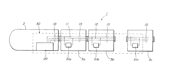
Figure 1 is a schematic block diagram of a train
consist equipped with a system for automatically detPrmining
the position of railroad cars within such train consist wherein
_ _ _ _ . . . . . , , . . , . .. _ .... , , _ _ _ _ _ .
2181869
the system includes a computer ~ituated within a locomotive of
such train consist; a vellicle computing device incorporated
into each such railroad car; and at least one trainline
interconnecting the computer with each of the vehicle computing
devic e s .
Figure 2 is a more detailed schematic diagram of the
vehicle computing device ;n~ S;n~ a mi~:Lu~lu~ssor; a load
applying device; a load sen~ing device; and a diode according
to the present invention along with unspecified circuitry
repre3enting electronics commonly found on such railroad cars
and unrelated to the present invention.
Figure 3 is a f low chart outline of a method f or
automatically det~rm;n;ng the position of railroad cars within
such train consist.
DETAILED DESCRIPTION OF THE INVENTION
Before presentillg a more detailed description of the
present railroad car po~3ition locating system and method, f or
the ~ake of clarity and understanding of the invention, the
reader is advised that identical c ,_lle,-Ls having identical
functions in each of the accompanying drawings have ~een marked
with the same reference numeral~ throughout both Figure3
illustrated herein.
Figures 1 and 2 illustrate the essential details of
a pre~ently preferred e~lbodiment of the present invention.
Speci~ Al ly, Figure 1 illustrates a train consist, generally
designated 1, equipped with a system, generally designated 50,
for automatically detf~rm; ni ng the position of railroad car~ 3
within such train consist 1. The system 50 includes: a
computer means 20 operating according to a proy . ; ng means
, .. . . ~
218186
.~,.
( not shown ) pref erably situated within a locomotive 2 of such
train consiat 1; a vehicle computing means 51 incorporated
within each such railroad car 3 and containing a unique
identif ication code; and at least one of a plurality of
tr~;nl ;n~ 10 interconnecting the computer means 20 with each
of the vehicle computing means 51a-51c.
The trainlines 10 of such train consist 1 include a
plurality of wires running f rom such head of train locomotive
2 to a last railroad car 3c in such train consist 1. Examples
of such tr~;nlinf~f~ 10 include, among others, a power line 11
and a return line 12. Each vehicle computing means 51 connects
to such power line 11 and a suitable electrical return such as
return line 12. Each vehicle computing means 51a-51c can both
apply an electrical signal to such power line 11 and sense when
another vehicle computillg means 51c-51a has applied the
electrical signal to such power line 11. Each vehicle
computing means 51a-51c is assigned a unique identification
code thereby also identifying the particular railroad car in
which it is installed.
The computer means 20 of the present invention may
take any one of several forms. As computerized systems are
standard equipment on many of today's locomotives, a
preexisting computerized system such as the WABCO EPIC19
Computer Controlled Brake System may serve as the computer
means 20 of the present system. Alternatively, a separate
computer device dedicated solely to the present invention may
serve as the computer means 20. Though space and weight
factors among others favor choosing the former alternative, one
skilled in the locomotive computer art would have the requisite
11
... . .. = = = = = _
2181869
competence to make and u3e the present invention no matter
which alternative was selected as the computer means 20.
The present railroad car position det-~rm;n;ng system
50 can be thought of having three phases of operation. The
first phase, involving the computer means 20 initially
receiving the identification codes from the vehicle computing
means 5 la-5 lc, can be ref erred to as the query phase . The
second phase, involving tlle computer means 20 c~ nfl;ng each
o~ the vehicle computing means 5 la-5 lc to apply the electrical
signal to such power line 11, can be referred to as the data
collection phase. The third phase, involving the computer
means 20 calculating the position of such railroad cars 3
within such train consist 1, can be referred to as the locating
phase .
Referring still to Figure 1, each of vehicle
computing means 51a-51c supplies its identification code to the
computer means 20 during the query phase of operation. The
query phase may occur either automatically or manually. The
query phase may occur automatically when power is ~irst applied
to both the computer mean3 20 and the vehicle computing means
51a-51c. For example, each vehicle computing means 51a-51c
automatically sends its identif ication code to the computer
means 20 as soon as the railroad car to which it is attached is
plugged into the tr;l;nl ;n~Y 10 of the train consist 1. The
query phase may also occur manually when a train operator
directs the computer means 20 via keyboard or similar input
device to query all of the vehicle computing means 5la-5lc for
their respective identif ication codes . AB fiuch railroad cars
3 are routinely added to and removed f rom such train consist
12
2181869
during train operation, the automatic option ig Pf~pPri~lly
useful as it allows such train operator to keep the computer
means Z0 updated with the most current vehicle computing
means/railroad car identification codes. Once the computer
means 20 procures all of the identification codes from the
vehicle computing means 51a-51c, the computer means 20 is
enabled to perform the data collection phase of system
operation .
During the data collection phase, the computer means
20 essentially conducts a series of tests to determine
automatically the relative positions of each of such railroad
cars 3 within such train consist 1. In the most general terms,
each test involves the computer means 20 alternately r~ nr~;n~
one of, and receiving responses f rom certain other of, the
vehicle computing means 51. Each time the computer means 20
C~ n-l~l one of the vehicle computing means 51 to apply the
electrical signal to such power line 11, each of all the other
vehicle computing means S 1 located oetween such locomotive 2
and one such railroad car 3 (whose vehicle computing means 51
so applied the electrical signal) senses the electrical signal.
Those other vehicle compl1ting means 51 located between such
locomotive 2 and one such railroad car 3 then each respond to
the computer means 20, via one of such trainlines 10, with an
indication that the electrical signal was sensed. The computer
means 20, after having c, n~iPll all of the vehicle computing
means 51 and having received the responses therefrom,
automatically de~PrTni ne~ the position that each such railroad
car 3 ocrllr; P-l within such train consist 1.
13
2181869
.
The query and data collection pha~es of operation of
the present system 50 call perhaps be best PYrlA;nPtl by the
following example which aasumes a train consist consisting of
four vehicles, i.e., one locomotive and three railroad cars, as
illustrated in Figure 1. When power is first applied to
present 3ystem 50 or when 5uch train operator so commands via
the computer means 20, eacll of the vehicle computing means 51a-
51c provides the computer means 20 with its identification
code . From the available identif ication codes, the computer
means 20 then randomly, or according to other criteria,
command~ one of the vehicle computing means (e.g., 51b) to
apply the electrical signal . The vehicle computing means 5 lb
then applies the electrical signal to such power line 11. As
the vehicle computing means 51a is the only vehicle computing
means located between sucll locomotive 2 and such railroad car
3b whose vehicle computing means 5 lb applied the electrical
signal to such power line 11, vehicle computing means 51a
senses the electrical signal generated by the vehicle computing
means 51b . The vehicle computing means 5 la then responds to
the computer means 20, via one of such trAinl inP~ 10, with an
indication that the electrical signal was sensed.
Supplied with data evidencing that the vehicle
computing means 51a is located forward of the vehicle computing
means 51b, the computer means 20 then randomly selects another
of the vehicle computing means (e.g., 51a). The vehicle
computing means 5 la then applies the electrical signal to such
power line 11. As there are no vehicle computing means located
between such locomotive 2 and such railroad car 3a whose
vehicle computing means 51a last applied the electrical signal
14
2181869
. ~.
to such power line 11, the computer means 20 now possesses data
evi~lPnrin~ that no railroad cars exist forward of railroad car
3a. The computer means 20 then randomly selects another (and,
in this example, the last ) of the vehicle computing means
( i . e ., 5 lc ) . The vehicle computing means 5 lc then applies the
electrical signal to such power line 11. As the vehicle
computing means 51a and 51b are the only vehicle computing
means located between such locomotive 2 and auch railroad car
3c whose vehicle computing means 5 lc last applied the
electrical signal to such power line 11, both the vehicle
computing means 51a and 51b 8ense the electrical signal
generated by the vehicle computing means 51c. Both the vehicle
computing means 5 la and 5 lb then respond to the computer means
20, via one of such trainlines 10, with an indication that the
electrical signal waa sensed. The computer means 20 now
possesses data evidencing that railroad cars 3a and 3b exist
f orward of railroad car 3c .
Elaving transmitted all of the available
identif ication codes to the vehicle computing mean3 51 and
having received the expected responses therefrom, the computer
means 20 then c n- PR th~ locating phase of aystem operation.
The computer means 20 processes the data collected from each
te8t to determine automatically the relative positions of each
of such railroad car 3 within such train consist 1. Using the
data provided by the above example, the f irst test supplied
evidence showing that railroad car 3a is located forward of
railroad car 3b. The serond test supplied evidence showing
that no railroad cars exi8t forward of railroad car 3a. The
third test supplied evidence that railroad cars 3a and 3b exist
2181869
. ~.
forward of railroad car 3e. The present syatem 50, using data
gathered in the data collection phase, would then determine in
its locating phase that locomotive 2 i6 f ollowed in order by
railroad cars 3a, 3b and 3c.
The vehicle ccmputing means 51 of the present
invention 50 may be impl~mented, among other ways, using a
circuit ~uch as that shown in Figure 2. In this instance, the
vehicle computing means 51 includes a means 52 for applying the
electrical signal to sueh power line 11; a means 58 for sensing
the electrical signal apE)lied to such power line 11; and a
mi.~ ucessor 60. The signal sensing means 58 may be
implemented using any one of several ways known in the
electrical sign;ll 1 ;ng art including a current sensor 59 as
shown in Figure 2. The microprocessor 60 directs the signal
applying means 52 to apply the electrical signal to such power
line ll when the mi~ ocessor 60 receives the appropriate
command from the eomputer means 20. The mieroprocessor 60 also
responds to the eomputer means 20 via sueh at least one
trainline when the signal sensing means 58 senses the
eleetrieal signal transmitted by another vehiele computing
means 51 that is situated on one of such railroad cars 3
located opposite from both such locomotive 2 and such railroad
car 3 on which said signa]L sensing means 58 is installed.
The signal applying means 52 of the present invention
may be implemented, among other ways, using the circuit
elements illustrated in Figure 2. In this circuit design, the
signal applying means 52 includes a resistor 53 and a
transistor 54 connected in series across such power line 11 and
sueh return line 12. When the mieroproeessor 60 reeeives its
16
. ~ 218186~
command from the computer means 20, the microprocessor 60
activates the transistor 54 thereby applying the electrical
signal to such power lil1e ll. The transistor 54 may be
selected to be a f ield ef f ect transistor ( FET ) .
As should be apparent to persons skilled in the
electrical si~n~l1;n~ art, whatever circuit elementa are chosen
for the uignal applying means 52, the electrical signal that it
generates should have a signature different from the electrical
activity usually found on such power line ll. For example, a
distinctive electrical signal, such as a current pulse of
magnitude and shape dif f erent f rom the current activity f ound
on such power line ll, may be generated using the resistor 53
and FET transistor 54 arrangement illustrated in Figure 2.
Likewi3e, the signal sensing means 58 may be
implemented using any one of several ways including a current
sensor 59 as shown in Figure 2 . Whatever circuit element ( 8 )
are chosen for the signal sensing means 52, it obviously should
be able to detect the electrical signal generated by the signal
applying means 58.
As should also be apparent to persons skilled in the
electrical signalling art, the design of the vehicle computing
means circuit permits a vehicle computing means installed on
one such railroad car ( e . g ., 3b ) to detect the electrical
signal transmitted by another vehicle computing means installed
on another such railroad car ( e . g ., 3c ) only when the latter
railroad car (e.g., 3c) is located opposite from both such
locomotive 2 and the f ormer railroad car ( e . g ., 3b ) . In other
words, those signal sensLng means installed within railroad
cars ( e . g ., 3b and 3c ) located rearward of the railroad car
17
2181869
( e . g ., 3a ) whose signal applying means applied the electrical
signal to such power line ll will not receive the electrical
signal . The ef f ect of the vehicle computing means circuit
design is to provide a 3ignal sensing means that receives
electrical signals coming f rom a rearward end, and not f orward
end, of such train consist 1.
An optional, though preferred, addition to the
present system 50 would be a diode 63 or like suppression
element included within the vehicle computing means 51 as shown
in Figure 2. The diode 63 would serve to isolate the present
sy~tem 50 from unspecified electronic circuitry 13 commonly
found on such railroad cars 3 and unrela~ed to the present
invention. Otherwise, such preexisting vehicle electronics 13
may interf ere electricalllr with the electrical signal applied
to and ~en3ed on such power line 11 by the pre~ent railroad car
position de~ ~rm; n; n~ system 50 .
Referring now to Figure 3, illustrated therein in
flow chart form are the essential details of a method,
generally designated 100, for ~ t~rm;n;nq the position of a
railroad car within a train consist. Such train con~i~t
includes a locomotive, a plurality of trA;nl ;n~ and at least
one such railroad car. Such locomotive has a computer means
for controlling the operation of the locomotive. Such
trA;nl;n--~ include a power line for supplying power to the
computer means and to each railroad car and each railroad car
includes a vehicle computing circuit that is assigned a unique
identification code. The method 100 includes the steps of
supplying lZ0 the computer means with all of the identification
codes assigned to the vehicle computing circuits via at least
18
2181869
.
one trainline; and ~ rl;ng 130 sequentially, through the
computer means, each v~hicle computing circuit, via its
assigned identification code, to apply an electrical signal to
such power line wherein tlle electrical signal is recognizable
by all of the vehicle computing circuits.
The railroad car locating method 100 also includes
the step 140 of sensing the electrical signal and reaponding to
the computer means with an indication that the electrical
signal was ~ensed. Sper; ~ l l y, after each vehicle computing
circuit has applied the electrical signal to the power line,
for each of all other vehicle computing circuits located
between the locomotive and the vehicle computing circuit which
applied the electrical sigl1al, the electrical signal is sensed.
For each of those other vehicle computing circuits so located,
the computer means, via at least one trainline, receives a
response indicating that the electrical signal wa~a sensed.
The railroad car locating method 100 additionally
includes the step of repeating 150, in order, the c~ n~l;n~
step 130 and the sensing and responding step 140 until all the
vehicle computing circuits have applied the electrical signal
to such power line and responded appropriately to the computer
means. The method 100 next includes the step of de~rm;n;n~
160 automatically via the computer means, using data
representing the commands and the responses thereto, the
po3ition of each railroad car relative to the positions of all
other railroad cars within the train consist.
19
2~8186q
As such locomotives typically have a cab display for
monitoring train operation, the present method 100 may be
Pnh~n~-~d by including, after the detf-rminin~ step 160, the step
of di3playing 170 on such display the poRition of each railroad
car relative to the positions of all other railroad cars within
such train consist.
The reader should note that the present system and
method need not be limited solely to passenger or freight train
consist applications but. to any group of interconnected
vehicles .
While the presently pref erred embodiment and several
variations thereon for carrying out the present railroad car
position de~F-rmin;nq system and method have been set forth in
detail according to the Patent Act, those persons skilled in
the railroad control equipment art to which this invention
pertaina will recognize various alternative ways of practicing
the invention without departing from the 6pirit and 3cope of
the appended claims.
Accordingly, to promote the progress of science and
useful arts, I secure ~or myself by l~etters Patent exclusive
rights to all subject matter embraced by the following claims
f or a time prescribed by the Patent Act .