Note: Descriptions are shown in the official language in which they were submitted.
2182340
- 1 -
ITW Case 7053
HIGH VELOCITY, COMBUSTION-POWERED,
FASTENER-DRIVING TOOL
Technical Fi e1d of the Invention
This invention pertains to a high velocity,
combustion-powered, fastener-driving tool, in which a
driving piston, a driving blade, and a piston chamber
are arranged so that combustion of a fuel in a
combustion chamber imparts energy to the driving piston
and the driving blade so as to drive the driving piston
and the driving blade over a stroke having a length
sufficient to enable the driving blade to transfer more
than one half of the maximum, transferable energy to a
fastener, and so that the driving piston and the
driving blade are guided solely within the axial length
of the driving piston, over at least substantially all
of the stroke.
Background of the Invention
Combustion-powered, fastener-driving tools of a
type exemplified in Nikolich U.S. Patent Re. 32,452 and
Nikolich U.S. Patent No. 5,197,646 are available
commercially from ITW Paslode (a unit of Illinois Tool
Works Inc.) of Vernon Hills, Illinois, and are used
widely in building construction.
Typically, such a tool comprises a combustion
chamber, a piston chamber communicating with the
combustion chamber, a driving piston movable within the
piston chamber over a stroke between an initial
position and a terminal position, and a driving blade
mounted to the driving piston so as to be conjointly
movable with the driving piston. Combustion in the
combustion chamber imparts energy to the driving piston
and the driving blade so as to drive the driving piston
and the driving blade over a stroke from an initial
position toward a terminal position with the driving
blade preceding the driving piston. Typically, the
2 I X2340
- 2 -
driving blade is guided by passing through or between
guides, over the entire stroke of the driving blade.
Generally, such a tool also comprises means for
sensing when the tool is pressed against a workpiece,
for enabling the tool when the tool is pressed against
a workpiece, and for disabling the tool when the tool
is not pressed against a workpiece, together with means
including a trigger for initiating combustion in the
combustion chamber when the tool is enabled and the
trigger is actuated.
It has been found that such tools known heretofore
transfer less than one half of the maximum,
transferable energy to a fastener engaged by the
driving blade as the driving piston and the driving
blade approach the terminal position. It would be
highly desirable to provide such a tool that could
transfer substantially more of the maximum,
transferable energy to a fastener engaged by the
driving blade as the driving piston and the driving
blade approach the terminal position.
Summary of the Invention
A first aspect of this invention stems from a
discovery that increasing the ratio of the piston
displacement volume to the combustion chamber volume,
as by lengthening the stroke of the piston, increases
the fraction of the imparted energy that can be thus
transferred until a maximum, transferable energy is
approached, whereupon such fraction begins to fall as
such ration is increased further. A second aspect of
this invention stems from a discovery that, since
friction within the tool affects the fraction of the
imparted energy that can be thus transferred and since
the driving blade tends to buckle if elongated
excessively, it is advantageous for the driving piston
and the driving blade to be guided solely within the
axial length of the driving piston, over substantially
- 3 - 2182340
all of the stroke, so as to minimize friction within
the tool.
According to the first aspect of this invention,
this invention provides a combustion-powered, fastener-
s driving tool of the type noted above, wherein the
driving piston, the driving blade, and the piston
chamber are arranged so that combustion in the
combustion chamber having a combustion chamber volume
imparts energy to the driving piston and the driving
blade so as to drive the driving piston and the driving
blade from the initial position toward the terminal
position, through a piston displacement volume, with
the driving blade preceding the driving piston, wherein
the ratio of the piston displacement volume to the
combustion chamber volume is sufficient to enable the
driving blade to transfer more than one half of the
maximum, transferable energy to a fastener engaged by
the driving blade as the driving piston and the driving
blade approach the terminal position, preferably being
sufficient to enable the driving blade to transfer more
than eight tenths of the maximum, transferable energy
to a fastener engaged by the driving blade as the
driving piston and the driving blade approach the
terminal position. The ratio of the piston chamber
volume to the combustion chamber volume can be
advantageously increased by lengthening the stroke of
the piston.
According to the second aspect of this invention,
this invention provides a combustion-powered, fastener-
driving tool of the type noted above, wherein the
driving piston, the driving blade, and the piston
chamber are arranged so that the driving piston and the
driving blade are guided solely within the axial length
of the driving piston, over at least substantially all
of the stroke.
2182340
- 3a -
The invention in one broad aspect provides a
combustion-powered, fastener-driving tool of a type
deriving motive power from combustion of a gaseous fuel,
the tool comprising structure defining a combustion
chamber, and structure defining a piston chamber
communicating with the combustion chamber, with the piston
chamber having an inner, cylindrical wall. A driving
piston is movable within the piston chamber between an
initial position and a terminal position over a stroke. A
driving blade is mounted to the driving piston so as to be
conjointly movable with the driving piston over a stroke.
Means is provided for sensing when the tool is pressed
against a workpiece, for enabling the tool when the tool is
pressed against a workpiece and for disabling the tool when
the tool is not pressed against a workpiece. Means
including a trigger is provided for generating a spark for
initiating combustion of a gaseous fuel in the combustion
chamber when the tool is enabled and the trigger is
actuated, wherein the driving piston has an axial length,
wherein the driving piston, the driving blade and the
piston chamber are arranged so that the driving piston and
the driving blade are guided solely within the axial length
of the driving piston, over at least substantially all of
the stroke.
Preferably, the piston chamber has an inner,
. ~ __ 21823~Q
- 4 -
cylindrical wall, and the driving piston has an annular
portion with an annular groove, in which a piston ring
is seated and engages the inner, cylindrical wall.
These and other objects, features, and advantages
of this invention are evident from the following
description of two contemplated embodiments of this
invention with reference to the accompanying drawings.
Brief Description of the Drawings
Figure 1 is a perspective, schematic view of
elements of a high velocity, combustion-powered,
fastener-driving tool constituting one contemplated
embodiment of this invention.
Figure 2, on a larger scale, is a sectional view
taken along line 2-2 of Figure 1, in a direction
indicated by arrows.
Figure 3, on a similar scale, is a fragmentary,
cross-sectional view taken through an axis of the tool
shown in Figure 1.
Figure 4, on a similar scale, is a fragmentary,
cross-sectional view taken through an axis of a high
velocity, combustion-powered, fastener-driving tool
constituting an alternative embodiment of this
invention.
Figure 5 is a sectional view taken along line 5-5
of Figure 4, in a direction indicated by arrows.
Figure 6 is a simplified, longitudinal section
taken through a high velocity, combustion-powered,
fastener-driving tool constituting a preferred
embodiment of this invention.
Figure 7 is a graph of piston chamber volume
versus energy (joules) for such tools having combustion
chambers of six different volumes.
Figure 8 is a graph of (inches) versus energy
(joules) for such tools having combustion chambers of
six different volumes.
Detailed Description of the Illustrated Embodiments
- 5 - 2182344
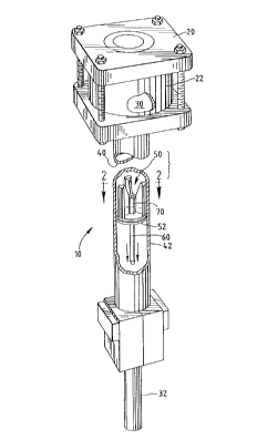
As shown schematically in Figures 1, 2, and 3, a
high velocity, combustion-powered, fastener-driving
tool 10 of the type noted above constitutes one
contemplated embodiment of this invention. Except as
illustrated and described herein, the tool 10 may be
substantially similar to one of the combustion-powered,
fastener-driving tools disclosed in Nikolich U.S.
Patents Re. 32,452 and No. 5,_197,646. the disclosures
of which may be referred to for further detail.
Being of the type noted above and deriving motive
power from combustion of a gaseous fuel, the tool 10
comprises a housing structure 20 and a cylinder body
22, which is mounted fixedly within the housing
structure 20, and which defines a combustion chamber
30, a piston chamber 40 communicating with the
combustion chamber 30, and a nosepiece 32 communicating
with the piston chamber 40. The combustion chamber 30,
the piston chamber 40, and the nosepiece 32 define an
axis of the tool 10. The combustion chamber 30 is
adapted to contain a mixture of such a fuel and air.
The nosepiece 32 is adapted to receive a fastener and
to guide the fastener as the fastener is driven.
Moreover, the tool 10 comprises a driving piston
50 movable axially within the piston chamber 40 over a
stroke between an initial position, which is 'an upper
position in the drawings, and a terminal position,
which is a lower position in the drawings. The driving
piston 50 has an axial length, to which reference is to
be later made. Furthermore, the tool 10 comprises a
driving blade 60, which is mounted to the driving
piston 50 so as to be conjointly movable with the
driving piston 50. Generally, the terminal position is
defined by an annular, elastomeric bumper 90, which is
arranged to arrest the driving piston 50 as the driving
piston 50 and the driving blade 60 approach the
terminal position. The combustion chamber 30 has a
2 i $~~4-~ -_
- 6 -
volume, which is measured with the driving piston 50
and the driving blade 60 in the initial position. As
the driving piston 50 and the driving blade 60 are
moved from the initial position into the terminal
position, the driving piston 50 is displaced through a
volume, which may be conveniently called the piston
displacement volume.
As disclosed in Nikolich U.S. Patent No. 5,197,646
noted above, the tool 10 comprises means including a
workpiece-contacting element for sensing when the tool
is pressed against a workpiece, for enabling the tool
10 when the tool 10 is pressed against a workpiece, and
for disabling the tool 10 when the tool 10 is not
pressed against a workpiece, means including a trigger
for initiating combustion of a gaseous fuel mixed with
air in the combustion chamber 30 when the trigger is
actuated. Details of these means and other elements of
the tool 10 are outside the scope of this invention and
can be readily supplied by persons having ordinary
skill in the art from the Nikolich patents noted above
and from other sources.
As discussed above, the first aspect of this
invention stems from the discovery that increasing the
ratio of the piston displacement volume to the
combustion chamber volume, as by lengthening the stroke
of the piston, increases the fraction of the imparted
energy that can be thus transferred until a maximum,
transferable energy is approached, whereupon such
fraction begins to fall. This discovery is illustrated
by the graph of Figure 7, which shows the energy
transferable by a driving blade to a fastener at
strokes of different lengths, for combustion-powered,
fastener-driving tools of the type noted above with
different combustion chamber volumes, and by the graph
of Figure 8, which shows the energy transferable by a
driving blade to a fastener at different piston
21 ~~3~-
_7-
displacement volumes for combustion=powered, fastener-
driving tools of the type noted above with different
combustion chamber volumes. All numbers shown on the
graphs (Figures 7 and 8) are approximate.
According to the first aspect of this invention,
the driving piston 50, the driving blade 60, and the
piston chamber 40 are arranged so that combustion in
the combustion chamber 30 imparts energy to the driving
piston 50 and the driving blade 60 so as to drive the
driving piston 50 and the driving blade 60 from the
initial position toward the terminal position with the
driving blade 60 preceding the driving piston 50, over
a stroke having a length sufficient to enable the
driving blade 60 to transfer more than one half of the
maximum, transferable energy to a fastener engaged by
the driving blade 60 as the driving piston 50 and the
driving blade 60 approach the terminal position,
preferably over a stroke having a length sufficient to
enable the driving blade 60 to transfer more than eight
tenths of the maximum, transferable energy to a
fastener engaged by the driving blade 60 as the driving
piston 50 and the driving blade 60 approach the
terminal position.
As an example of such tools known heretofore, one
model of a combustion-powered, fastener-driving tool
available commercially from Illinois Tool Works Inc.
has a combustion chamber with a volume of approximately
17 cubic inches and a stroke of approximately 3.5
inches, utilizes a given quantity of a gaseous fuel,
and is capable of transferring approximately 50 joules
to a fastener, which energy (50 joules) is
approximately 0.417 (less than one half) of the maximum
energy (120 joules) transferable in such a tool. As an
example of such tools embodying this invention, an
experimental, combustion-powered, fastener-driving tool
having a combustion chamber with a volume of
~ia2340
_8_
approximately 17 cubic inches but a stroke of
approximately seven inches and utilizing approximately
the same quantity of the same fuel is capable of
transferring approximately 100 joules to a fastener,
whica energy (100 joules) is approximately 0.833 times
(more than eight tenths) of the maximum energy (120
joules) transferable in such a tool.
As discussed above, the second aspect of this
invention stems from a discovery that for reducing
friction within such a tool so as to increase the
fraction of the maximum, transferable energy that can
be thus transferred it is advantageous for the driving
piston 50 and the driving blade 60 to be guided solely
within the axial length of the driving piston 50, over
substantially all of the stroke.
Thus, the piston chamber 40 has an inner,
cylindrical wall 42, and the driving piston 50 has an
annular portion 52 with an annular groove 54, in which
a piston ring 56 is seated. The piston ring 56 engages
the inner, cylindrical wall 42, so as to provide a gas-
tight seal between the driving piston 50 and the
cylindrical wall 42 as the driving piston 50 and the
driving blade 60 are driven axially. The driving
piston 50, which has a small mass, has a central hub
70, which trails the annular portion 52, three radial
arms 72, which radiate from the central hub 70, and
three axially extending guides 74, each of which is
connected to the central hub 70 by one of the radial
arms 72 and each of which has an outer face 76
conforming to the cylindrical wall 42. As the driving
piston 50 and the driving blade 60 are driven axially,
these axially extending guides 74 help to guide the
driving piston 50 and the driving blade 60 along the
cylindrical wall 42 and serve to prevent tilting of the
driving piston SO and the driving blade 60 from the
axis to any significant degree.
2 i 8~3~-~
- 9 -
As shown schematically in Figures 4 and 5, a high
velocity, combustion-powered, fastener-driving tool 100
of the type noted above constitutes an alternative
embodiment of this invention. The tool 100 is designed
to,drive fasteners exemplified by the illustrated
fastener F of a type exemplified in Almeras et a1. U.S.
Patent No. 4,824,003 and Dewey et a1. U.S. Patent No.
5,193,729. Except as illustrated and described herein,
the tool 100 may be substantially similar to the tool
10 and to one of the combustion-powered, fastener-
driving tools disclosed in Nikolich U.S. Patents Re.
32,452 and No. 5,197,646, supra.
The tool 100 comprises structure defining a
combustion chamber (not shown) along with structure
defining a piston chamber 120 having an inner,
cylindrical wall 122, a driving piston 130 movable
axially within the piston chamber 120 over a stroke
between an initial position, which is an upper position
in the drawings, and a terminal position, which is a
-lower position in the drawings. The driving piston 130
is shown in the terminal position.
Furthermore, the tool 100 comprises a driving
blade 160, which is mounted to the driving piston 130
so as to be conjointly movable with the driving piston
130. Generally, the terminal position is defined by an
annular, elastomeric bumper 170, which is arranged to
arrest the driving piston 130 as the driving piston 130
and the driving blade 160 approach the terminal
position.
As shown, the driving piston 130 has a central hub
132 between two axially spaced, annular portions 134,
136, a leading one of which 134 has an annular groove
138 with a piston ring 170 seated in the annular groove
138 and engaging the inner, cylindrical wall 122.
Also, the trailing portion 136 has four generally
cylindrical openings 180, so as to reduce the mass of
218340
- 10 -
the driving piston 130.
As shown in Figure 6, a combustion-powered,
fastener-driving tool 200 for driving fasteners like
the fastener F shown in Figure 4 constitutes a
preferred embodiment of this invention. The tool 200
is similar to the tools described above, particularly
the tool 10, and comprises structure defining a
combustion chamber 210, structure defining a piston
chamber 220 having an inner, cylindrical wall 222, a
driving piston 230 movable axially within the piston
chamber 220 over a stroke between an initial position,
which is an upper position in the drawings, and a
terminal position, which is a lower position in the
drawings.
Being similar to the driving piston 50, the
driving piston 230 has an annular portion 232 with an
annular groove 234, in which a piston ring 236 is
seated. The piston ring 236 engages the inner,
cylindrical wall 222, so as to provide a gas-tight seal
between the driving piston 230 and the cylindrical wall
222 as the driving piston 230 and the driving blade 260
are driven axially. The driving piston 230, which has
a small mass, has a central hub 240, which trails the
annular portion 232, three radial arms 242, which
radiate from the central hub 240, and three axially
extending guides 244, each of which is connected to the
central hub 240 by one of the radial arms 242 and each
of which has an outer face 246 conforming to the
cylindrical wall 222.
The tool 200 comprises means including a
workpiece-contacting element 240 for sensing when the
tool 200 is pressed against a workpiece, for enabling
the tool 200 when the tool 200 is pressed against a
workpiece, and for disabling the tool 200 when the tool
200 is not pressed against a workpiece, means including
a trigger 250 for initiating combustion of a gaseous
z ~ sz~~o
- 11 -
fuel mixed with air in the combustion chamber 30 when
the trigger is actuated. Details of the means
including the workpiece-contacting element 240, the
means including the trigger 240, and other elements of
the tool 200 are outside the scope of this invention
and can be readily supplied by persons having ordinary
skill in the art from the Nikolich patents noted above
and from other sources.
Furthermore, the tool 200 comprises a driving
blade 260, which is mounted to the driving piston 230
so as to be conjointly movable with the driving piston
230. Generally, the terminal position is defined by an
annular, elastomeric bumper 270, which is arranged to
arrest the driving piston 230 as the driving piston 230
and the driving blade 260 approach the terminal
position.
The second aspect of this invention, as described
above, may prove to be also advantageous in a
pneumatically powered, fastener-driving tool of a type
exemplified in Golsch~U.S. Patent No. 4,932,480, as
well as in a combustion-powered, fastener-driving tool.
various modifications may be made in the
illustrated embodiments described above without
departing from the scope and spirit of this invention.