Note: Descriptions are shown in the official language in which they were submitted.
2 1 82348
EXHAUST PASSAGE STRUCTURE OF OUTBOARD MOTOR UNIT
BACKGROUND OF THE INVENTION
The present invention relates to an exhaust
passage structure of an outboard motor unit.
Recently, in order to prevent air contamination
and water contamination, catalyst is disposed on the way
of an exhaust passage of an outboard motor unit and
downstream side of an exhaust expansion chamber so as not
to prevent the flow of the exhaust gas, and an attention is
paid to the location of the catalyst above the draft line
of a hull because the catalyst is degraded or damaged in
contact with water component such as sea water.
For example, such location of the catalyst is
disclosed in Japanese Patent Laid-open Publication Nos. HEI
5-52112 and 6-146876.
In an outboard motor shown in the Japanese Patent
Laid-open Publication No. HEI 5-52112, a catalyst is
disposed to an upper end of a second exhaust tube of an
exhaust expansion chamber formed in a drive shaft housing,
and in such location of the catalyst, it is necessary to
extend upward the drive shaft housing or to extend the
exhaust expansion chamber far above the drive shaft housing
so that the catalyst does not contact the sea water when
the draft line of the sea water rises, thus being
21 82348
troublesome and disadvantageous.
Furthermore, in an outboard motor shown in the
Japanese Patent Laid-open Publication No. HEI 6-146876, an
exhaust expansion chamber is formed below an engine unit
and a first exhaust passage is also formed so as to open
to the exhaust expansion chamber. A second exhaust passage
is further formed so as to communicate the exhaust
expansion chamber with an underwater exhaust port, and a
portion on the way of the second exhaust passage is bent to
provide a counterflow preventing section. According to such
structure, an exhaust resistance increases and, hence, an
engine power is reduced.
SUMMARY OF THE INVENTION
An object of the present invention is to
substantially eliminate the problems or defects mentioned
above and to provide an exhaust passage structure of an
outboard motor unit capable of reducing an exhaust
resistance with an exhaust passage having less bent
structure.
Another object of the present invention is to
provide an exhaust passage structure of an outboard motor
unit capable of preventing a catalyst from being degraded
in contact with a sea water, for example.
A further object of the present invention is to
provide an exhaust passage structure of an outboard motor
21 82348
unit capable of cooling an exhaust gas after passing the
catalyst and preventing a drive shaft housing from
increasing in temperature.
A still further object of the present invention
is to provide an exhaust passage structure of an outboard
motor unit capable of reducing a manufacturing cost and
improving an assembling performance.
These and other objects can be achieved according
to the present invention by providing an exhaust passage
structure of an outboard motor unit having an engine holder
mounted to a hull through a bracket, an engine disposed to
an upper portion of the engine holder, a drive shaft
housing disposed to a lower portion of the engine holder
and an exhaust passage structure extending from the engine
into water through the drive shaft housing, the improvement
in which first and second exhaust expansion chambers are
disposed on the way of an exhaust passage of the exhaust
passage structure, the second exhaust expansion chamber is
disposed to an upper portion of the engine holder, an
exhaust tube is disposed on an upstream side of another
exhaust passage which communicates the second exhaust
expansion chamber with the water so that an upstream side
opening of the exhaust tube is directed upward in a mounted
state, the opening being opened at a position between the
location of the bracket and an upper end of an engine
cylinder so that the water does not enter the second
21 82348
exhaust expansion chamber even if a draft line of the water
rises.
In a preferred embodiment, a catalyst is disposed
in the first exhaust expansion chamber, and the opening of
the exhaust tube is opened at a position between the
location of the catalyst and the upper end of the engine
cylinder.
A cooling water jacket is disposed around the
second exhaust expansion chamber. The first and second
exhaust expansion chambers are integrally formed with each
other.
According to the present invention of the
characters described above, the opening of the exhaust
tube is opened at a portion at which the water does not
enter the second exhaust expansion chamber even if a draft
line of the water rises. Preferably, this position is
between the location of the catalyst or bracket and the
upper end of the engine cylinder. The catalyst is disposed
inside the first exhaust expansion chamber. Accordingly, it
is not necessary to bend the exhaust passage to provide a
counterflow preventing section, thus reducing the exhaust
resistance and preventing the catalyst from contacting the
water such as sea water.
The location of the cooling water jacket around
the second exhaust expansion chamber prevents the drive
shaft housing from increasing in temperature and weakens
21 82348
the exhaust noise.
The manufacturing cost may be reduced by
integrally forming the first exhaust expansion chamber and
the exhaust passage which will result in the improvement of
the assembling performance of the outboard motor unit.
The nature and further characteristic features of
the present invention will be made more clear from the
following descriptions made with reference to the
accompanying drawings.
BRIEF DESCRIPTION OF THE DRAWINGS
In the accompanying drawings:
Fig. 1 is an elevational section of an outboard
motor unit according to one embodiment of the present
invention; and
Fig. 2 is a sectional view taken along the line
II-II in Fig. 1.
DESCRIPTION OF THE PREFERRED EMBODIMENT
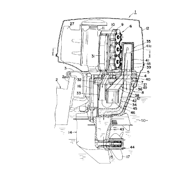
With reference to Fig. 1, an outboard motor unit
1 according to the embodiment of the present invention is
mounted to a transom 2a of a hull 2 through a bracket 3.
The outboard motor unit 1 is e~uipped with an engine holder
4 connected to the bracket 3. An engine 6 is disposed at an
upper portion of the engine holder 4 through an oil seal
housing 5 and a drive shaft housing 8 is also disposed at a
21 82348
lower portion of the engine holder 4 through an exhaust
manifold 7.
As shown in Figs. 1 and 2, the engine 6 is for
example a water cooled two-stroke-cycle V-type six-cylinder
engine, which is composed of a cylinder head 9, a cylinder
block 10, a crank case 11, etc, and a pair of cylinder
blocks lO are arranged so as to provide a V-shape, thus
providing a V bank 20 between the cylinder blocks 10. The
engine 6 is covered by an engine cover 12, and a crank
shaft 13 is mounted perpendicularly as viewed in the crank
case 11 to be rotatable.
A gear case 14 is disposed below the drive shaft
housing 8 and a propeller shaft 15 driven by the engine 6
is supported to be rotatable. The rotation of the engine 6
is transmitted to the propeller shaft 11 through a drive
shaft 16 connected to the crank shaft 13 and a bevel gear,
not shown, to thereby drive a propeller 17 supported to a
rear end of the propeller shaft 11.
Pistons 21 are fitted into the respective
cylinders of the cylinder assembly 18 and the pistons 21
are connected to crank pins 22 of the crank shaft 13
through connection rods 23 in a manner that reciprocal
strokes of the pistons 21 are converted to rotational
motion of the crank shaft 13. A combustion chamber 24 is
formed to a connection portion between the cylinder head 9
and the cylinder block lO, and an ignition plug 25 is
21 823~8
screwed to a central portion of the combustion chamber from
the outside thereof.
A lead valve unit 26 as a suction valve unit is
disposed in the crank case 11. A surge tank 27 is disposed
on the upstream side of the lead valve unit 26 and a
suction tube 29 provided with a throttle 28 is also
connected to a further upstream side thereof. In the surge
tank 27, a fuel injector 30 is mounted from an external
side so as to jet a fuel towards the upstream side of the
lead valve unit 26.
Exhaust ports 31a are formed to the inner
peripheral surfaces of the respective cylinders at portions
outside the V-bank 20, and these exhaust ports are covered
by an exhaust gas collecting cover 31, which serves to
converge the exhaust gas exhausted through the respective
cylinders. The lower portion of the exhaust gas collecting
cover 31 is communicated with a first exhaust hole, i.e.
passage, 32 formed vertically through an oil seal housing
5, the engine holder 4 and the exhaust manifold 7 and
communicated with a first exhaust tube 33 connected to the
first exhaust hole 32.
A first exhaust expansion chamber 34 is formed to
the lower portion of the exhaust manifold 7 in the drive
shaft housing 8, and in the expansion chamber 34, the first
exhaust tube 33 is disposed so as to extend vertically as
viewed. A second exhaust chamber 35 is also formed to the
21 82348
upper portion of the oil seal housing 5 on the rear side
of the cylinder head 9 of the engine 6 with respect to the
advancing direction of the hull 2. These first and second
exhaust expansion chambers 34 and 35 are communicated with
each other through a communication passage 36 formed
substantially vertically. The communication passage 36 is
composed of a communication hole 37 formed through the oil
seal housing 5, the engine holder 4 and the exhaust
manifold 7, a second exhaust tube 38 connected to the
communication hole 37 and disposed in the first exhaust
expansion chamber 34, and a third exhaust tube 39 connected
to the communication hole 37 and disposed in the second
exhaust expansion chamber 35.
The oil housing 5, the engine holder 4 and the
exhaust manifold 7 are formed with a second exhaust hole 40
adjacent to the communication hole 37 in a vertical fashion
as viewed. A fourth exhaust tube 41 is arranged inside the
second exhaust expansion chamber 35 above the second
exhaust hole 40 so that the upstream side opening 41a is
directed upward and the fourth exhaust tube 41 is also
connected to the exhaust hole 40. The position of the
opening 41a of the fourth exhaust tube 41 is set at a
sufficiently high position so that, for example, sea water
does not invade into the second exhaust expansion chamber
35 even if a draft surface of the sea water rises. That is,
in the concrete structure of a preferred embodiment, as
2 1 82348
shown in Fig. 1, in the outboard motor unit being mounted
state, the lower limit of the position of the opening 41a
will be above the location of the bracket 3 or a catalyst
46, mentioned hereinafter, and the upper limit thereof will
be the upper end of the engine cylinder.
A first exhaust passage 42 is disposed below the
second exhaust hole 40 in an integral manner with respect
to the first exhaust expansion chamber 34. The first
exhaust passage 42 has an outlet side end connected to a
second exhaust passage 43 formed in the gear case 14. The
second exhaust passage 43 extends into water through an
exhaust gas discharge passage 44 formed around the
propeller shaft 15. As mentioned above, according to this
embodiment, the exhaust passage structure 45 is composed of
the first exhaust hole 32, the first exhaust tube 33, the
communication passage 36 (including the communication hole
37 and the second and third exhaust tubes 38 and 39), the
fourth exhaust tube 41, the second exhaust hole 40, the
first exhaust passage 42, the second exhaust passage 43 and
the exhaust gas discharge passage 44.
In the arrangement of the outboard motor unit of
the structure described above, a catalyst means 46 is
disposed at an opening portion on the side of the first
exhaust expansion chamber 34 of the communication passage
36, i.e. at a portion below the second exhaust tube 38.
A first water jacket 47 is formed around the
2 1 82348
first exhaust expansion chamber 34 and the first exhaust
passage 43, and a second water jacket 48 is also formed
around the second exhaust expansion chamber 35, in which
the cooling water fills.
The embodiment of the structure described above
will operate as follows.
The exhaust gas discharged from the respective
cylinders of the cylinder assembly 18 of the engine 6 is
once converged and collected by the exhaust gas collection
cover 31, and then, guided to the first exhaust expansion
chamber 34 by way of the first exhaust hole 32 and the
first exhaust tube 33. The exhaust gas guided to the first
exhaust expansion chamber 34 is cleaned by passing through
the catalyst 46, and then, guided to the second exhaust
expansion chamber 35 by way of the communication passage
36. The exhaust gas is thereafter discharged from the
second exhaust expansion chamber 35 into water through the
fourth exhaust tube 41, the second exhaust hole 40, the
first exhaust passage 42, the second exhaust passage 43 and
the exhaust gas discharge passage 44.
According to the present invention, the first
exhaust expansion chamber 34 is disposed below the engine
holder 4, the second exhaust expansion chamber 35 is
disposed above the engine holder 4, both chambers 34 and 35
being communicated through the communication passage 36,
and the first exhaust passage 42 integrally formed with the
1 0
21 82348
,.
first exhaust expansion chamber 34 extends downward.
According to such structure, the bent structure of the
exhaust passage 45 can be eliminated and, hence, it is not
necessary to bend the intermediate portion of the exhaust
passage 45 as in the conventional structure, thus reducing
the exhaust resistance and utilizing the pulsation of the
exhaust gas to thereby prevent the lowering of the engine
power.
Furthermore, at the time of engine operation
stopping or idling, water such as sea water fills partially
the first exhaust passage 42 as shown in Fig. 1, and at the
time of rapid engine speed reduction, the sea water 50 is
raised up to the first exhaust passage 42 by means of the
negative pressure caused in the exhaust passage 45.
However, according to the present invention, since the
fourth exhaust tube 41 is arranged so that the upstream
side opening 41a thereof is directed upward in the second
exhaust expansion chamber 35 at a portion sufficiently high
to prevent the sea water 50 from entering the second
exhaust expansion chamber 35 even if the draft line of the
sea water rises, thus preventing the sea water 50 from
directly contacting the catalyst 46.
Still furthermore, because the exhaust gas has a
high temperature and a high pressure, there is a fear of
increasing the temperature and the exhaust noise in the
exhaust passage 45. However, according to the present
2 1 82348
invention, the first and second exhaust expansion chambers
34 and 35 on the way of the exhaust passage 45 and the
first and second water jackets 47 and 48 are arranged
around these chambers 34 and 35, so that the exhaust gas is
cooled and the temperature of the drive housing 8 can be
hence prevented from increasing and the exhaust noise can
be also weakened.
According to the integral structure of the first
exhaust expansion chamber 34 with the first exhaust passage
42, the manufacturing cost can be reduced and the
assembling performance can be also improved.
Although, in the described embodiment, the
catalyst 46 is disposed within the first exhaust expansion
chamber 34, it may be disposed within the second exhaust
expansion chamber 35.