Note: Descriptions are shown in the official language in which they were submitted.
- 21824~5
LINED BEARING WITH WEAR SENSOR
BACKGROUND OF THE INVENTION
This invention relates generally to lined
bearings and, more particularly, to a lined bearing
with a sensor permitting remote monitoring of wear.
Lined bearings are used in a wide variety of
applications and, due to improvements in bearing
design and bearing materials, lined bearings are
now used in many applications where rolling element
bearings were used previously. On many aircraft,
for example, lined bearings with a liner of polymer
material may be used in place of needle roller
bearings to realize substantial savings in weight
and complexity. However, because large numbers of
such bearings are required to support the movable
control surfaces on large aircraft, considerable
effort and expense are required to periodically
check each of the lined bearings for excessive
wear.
The foregoing illustrates limitations known to
exist in present lined bearings. Thus, it is
apparent that it would be advantageous to provide
an alternative directed to overcoming one or more
of the limitations set forth above. Accordingly, a
suitable alternative is provided including features
more fully disclosed hereinafter.
SUMMARY OF THE INVENTION
In one aspect of the present invention, this
is accomplished by providing a lined bearing having
an axis, an inner bearing ring, an outer bearing
ring concentric with the inner bearing ring, one of
the bearing rings being stationary and the other
being rotatable about the axis, and a bearing liner
within an annular space between the bearing rings
- 2182445
and fixed to the stationary bearing ring. A pair
of electrical conductors is embedded in the bearing
liner, coiled in at least one loop encircling the
inner bearing ring, each of the electrical
conductors being electrically isolated and located
such that wear of the bearing liner will cause the
rotatable bearing ring to contact and electrically
connect the electrical conductors. An electrical
circuit detects the electrical connection to
indicate wear of the bearing liner.
In another aspect of the present invention,
this is accomplished by providing a system for
monitoring wear of several lined bearings.
The foregoing and other aspects will become
apparent from the following detailed description of
the invention when considered in conjunction with
the accompanying drawing figures.
BRIEF DESCRIPTION OF THE DRAWING FIGURES
Fig. l is a cross-sectional view of a typical
lined bearing according to the prior art;
Fig. 2 is a cross-sectional view of a lined
bearing with wear sensor illustrating a first
embodiment of the present invention;
Fig. 3 is a cross-sectional view of the lined
bearing with wear sensor of Fig. 2, following
excessive wear;
Fig. 4 is a cross-sectional view of a lined
bearing with wear sensor illustrating a second
embodiment of the present invention, following
excessive wear;
Fig. 5 is a schematic drawing of an electrical
circuit for monitoring the condition of the lined
bearing with wear sensor of the present invention;
Fig. 6. is a schematic drawing of an
alternative electrical circuit to monitor the
- 2182~5
condition of the lined bearing with wear sensor of
the present invention; and
Fig. 7 is a schematic drawing of a typical
aircraft application of the lined bearing with wear
sensor of the present invention.
DETAILED DESCRIPTION
Referring now to the drawings, Figure
illustrates lined bearing 10, typical of the prior
art, as used, for example, as an aircraft track
roller bearing. Outer bearing ring 12 and inner
bearing ring 14 are concentric about axis 16 and
are typically made of stainless steel. Bearing
liner 18, located within an annular space between
the bearing rings, may be made of a polymer
material.
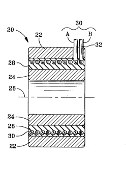
Figure 2 illustrates lined bearing 20 of the
present invention, including a wear sensor. Outer
bearing ring 22 and inner bearing ring 24 are
concentric about axis 26. One of the bearing rings
22 and 24 is stationary with respect to its
mounting, and the other bearing ring is rotatable
about axis 26. Bearing liner 28 is located within
an annular space between outer bearing ring 22 and
inner bearing ring 24 and is fixed to the
stationary bearing ring.
A pair of electrical conductors 30 is embedded
in bearing liner 28 such that each conductor,
designated A or B, is coiled in a helix or similar
form with at least one loop encircling inner
bearing ring 24. A and B alternate along the axial
length of the bearing and are electrically isolated
from each other. Electrical conductors 30 are
located within bearing liner 28, along the
stationary bearing ring, such that wear of the
bearing liner will cause the rotatable bearing ring
- 2182~5
to contact and electrically connect electrical
conductors A and B.
Preferably, bearing liner 28 is made of a low-
friction polymer, such as a TFE (teflon) composite,
and is a poor conductor of electricity, avoiding
the need to provide separate insulation of
electrical conductors 30. However, to ensure good
electrical isolation of the conductors, they can be
coated with enamel or other coating similar to that
used with magnet wire.
In the embodiment of Figure 2, outer bearing
ring 22 is stationary and inner bearing ring 24 is
rotatable about axis 26 relative to outer bearing
ring 22. At least one opening 32 within the
stationary bearing ring is provided to permit
electrical connection to detecting means and a
remote monitor by external wires.
Figure 3 illustrates lined bearing 20 after
excessive wear, and is enumerated as lined bearing
34 to distinguish the initial configuration. Outer
bearing ring 22 is unchanged, and inner bearing
ring 36 shows little wear but is no longer
concentric about axis 26. Bearing liner upper
portion 38 shows little wear, but bearing liner
lower portion 40 shows excessive wear. The
excessive wear causes shorting of electrical
conductors 30 due to contact with rotating inner
bearing ring 36, that is made of metal or is coated
to conduct electricity. If electrical conductors
30 are coated to ensure electrical isolation, as
described above, the coating will easily wear away
when the rotating bearing ring rubs against the
coating.
Figure 4 illustrates lined bearing 42 similar
to lined bearings 20 and 34 but having a stationary
- 21824~
inner bearing ring, as found in a typical track
roller bearing. Outer bearing ring 44 is similar
to outer bearing ring 22 of Figure 2. Inner
bearing ring 46 is not concentric about axis 48 due
to excessive wear of the rotating outer bearing
ring against bearing liner 50 at portion 52.
Electrical conductors 54 are coiled around inner
bearing ring 46 in alternating A and B locations to
indicate excessive wear, similar to electrical
conductors 30 of the first embodiment. Bearing
liner is fixed to stationary inner bearing ring 46
and is electrically connected to detector means and
a remote monitor through at least one opening 56.
Figure 5 illustrates schematically a simple
means for detecting the electrical connection of
electrical conductors 30 or 54 that results with
excessive wear. Ohmmeter 60 senses the decreased
electrical resistance between A and B and can serve
as a remote monitor of the lined bearing.
Alternatively, power source 62 may apply a voltage
to either A or B, as illustrated schematically in
Figure 6, and voltmeter 64 may be used as a remote
monitor of the lined bearing. Resistors 66 and 68
serve as biasing resistors and transistor 70 serves
as a switch. When electrical conductors 30 or 54
are shorted, current will no longer flow, signaling
excessive wear.
Figure 7 illustrates schematically fuselage 72
of an airplane equipped with several lined bearings
74 along rear control surface 76 of wing 78.
Electrical wires 80, in pairs, are joined as cable
82 connecting lined bearings 74 to signal
processing means 84. Signal processing means 84
may be a simple switch enabling manual connection
of a detector similar to those of Figures 5 an 6 to
- ~182445
one of lined bearings 74 or may be more automated,
such as a computerized multiplexer and signal
conditioner for sequential testing of lined
bearings 74. Output for signal processing means 84
may be connected by electrical wires 86 to a
warning lamp or other cockpit display 88. The
signal processing means may also, be made
detachable for use by ground crews, if the built-in
test feature is not desired.
From the above description, it will be
apparent that the present invention provides an
effective and convenient means of monitoring lined
bearings to sense excessive wear. Electrical
conductors that serve as sensing elements are
placed selectively with the bearing liner to permit
only the desired amount of wear, and electrical
connections are led through the stationary bearing
ring without interfering with operation of the
lined bearings. The wear sensor of the present
invention is particularly suited for use with
airplane control surfaces using large numbers of
lined bearings.
-- 6