Note: Descriptions are shown in the official language in which they were submitted.
2 1 82462
RAILWAY BRARE VAL~E ASSEMBLY
Backqround of the Inv~ iQn
The present invention relates generally to fluid-
actuated braking systems, such as the type frequently
installed on railway vehicles. More particularly, the
invention relates to an improved valve assembly which
may be used in such a braking system.
Although its basic concepts were developed many
years ago, the air brake system remains in widespread
use, particularly in the railway industry. As implied
by the name, air brake systems utilize pressurized air
to actuate the respective brakes of a vehicle, for
example, a railway vehicle. This air is typically
supplied by a reservoir located on-board the vehicle,
which is "charged" to a desired fluid pressure.
Flow of air between the reservoir and the brake
is controlled by a relatively large fluid valve. The
valve itself is generally constructed having two or
more internal valves to permit multiple states of
fluid transfer. Typically, these internal valves are
individually controlled by electric solenoids.
Due to operating voltage limitations, the brake
solenoids often produce a relatively small operating
force. This is in contrast with the relatively large
force often imposed on the internal valve r?-h~n;sm
due to fluid pressure~ In fact, the fluid force may
often exceed the solenoid force by greater than ten
(10~ times.
In the past, the disparity between the fluid
force and the solenoid force has often been addressed
utilizing a pilot valve design. Instead of acting
directly on the valve, the solenoid in this design
functions to control a sm~ller valve that regulates
the pilot supply. Air from the pilot supply in turn
. ,, . . . . .. _ . . _ _ _
~ 2 ~ 82462
actuates a piston connected to the larger valve
-hr~n;qm. Movement of the piston thus causes the
larger valve m?ch~n;Sm to move into and out of
engagement with its associated valve seat.
While the pilot valve design is effective to
~vel~ ? the disparity between the fluid force and the
solenoid force, it has several disadvantages. In
particular, this construction requires an additional
air supply, i.e., the pilot supply, that is otherwise
unnecessary for brake operation. Various parts are
also required in the valve itself to regulate
operation of the additional air supply.
Furthermore, the valve r?~h~nicm does not move
immediately upon actuation of the solenoid. Instead,
the larger valve is actuated only when the pilot
supply imposes a sufficient force on the piston. This
sequential operation limits the response time of the
larger valve.
Various attempts have been made to provide
suitable direct-acting valves by reducing the fluid
imh~Anrr? in the valve, thus cancelling the effects of
the fluid force. In some such designs, seals are
utilized to balance the fluid pressure in the valve.
These seals, however, have often caused a relatively
25 - large amount of friction that the solenoid, as well as
any return spring, must overcome as the valve
mr?r-h;qn;qm i5 moved.
other direct-acting valves have utilized
diaphragms in an attempt to balance the fluid forces.
Due to the configuration of the diaphragms, however,
these valves may still exhibit undesirable force
;mh~ nce in certain situations.
8unma~y of thc T~ention
The present invention recognizes and addresses
the foregoing disadvantages, and others, of prior art
2~82462
constructions and methods. Accordingly, it is an
object of the present invention to provide an improved
fluid valve.
It is a specific object of the present invention
to provide an improved brake valve assembly
particularly useful in railway applications.
It is another object of the present invention to
provide an improved brake valve assembly that
eliminates the need for a pilot supply.
It is another object of the present invention to
provide an improved brake valve assembly that achieves
relatively quick response time.
It is another object of the present invention to
provide an improved brake valve assembly that
substantially achieves balance throughout its
operation.
Some of these objects are achieved by an improved
brake valve assembly suitable in many embodiments for
use on a railway vehicle. The valve assembly includes
a valve housing defining a supply port, a delivery
port, an exhaust port and an interconnecting conduit.
The interconnecting conduit provides fluid
communication between first and second valve devices
within the valve housing. The valve devices are
~ controllable by respective electric solenoids to
effect multiple states of fluid communication between
the supply port, the delivery port and the exhaust
port.
The multiple states of fluid communication
preferably include a fluid delivery state wherein a
first fluid flow path is defined between the supply
pOrt and the delivery port. A fluid exhaust state is
also preferably provided wherein a second fluid flow
path is defined between the delivery port and the
exhaust port. A lap state may be provided to block
-
~ 21 82462
fluid communication between the supply port, the
delivery port and the exhaust port.
Each of the internal valve devices includes a
valve element that directly moves into and out of
engagement with an associated valve seat upon
actuation of the respective solenoid. To balance
internal fluid forces, each of the valve devices
further includes at least one'counterbalance assembly.
In an exemplary embodiment, the first valve device may
be equipped with a single counterbalance assembly,
with the second valve device having a pair of
oppositely-directed counterbalance assemblies.
Each of the counterbalance assemblies is
operatively connected in fluid opposition to the valve
element when engaging the valve seat. Thus, the
counterbalance assembly will provide a fluid force
opposite to that imposed on the engaged valve element.
Advantageously, the effective area of a respective
counterbalance assembly will also preferably remain
substantially equal to that of the associated valve
seat throughout the predetermined axial range through
which the valve element moves.
In exemplary embodiments, each counterbalance
assembly comprises a flexible, rolling diaphragm
~ disposed adjacent to a diaphragm follower. The
diaphragm follower may be constructed having a
cylindrical cup portion integrally extending into a
flanged rim portion distal from the valve seat.
In multiple-state embodiments, the first valve
device may include a pair of valve seats respectively
associated with the supply port and the exhaust port.
A single valve element may be provided in such
embodiments to reciprocatively move between the pair
of valve seats. The second valve device may include a
single valve seat, associated with the delivery port.
~ 2 1 82462
Other objects of the invention are achieved by a
valve assembly for selectively regulating flow of a
fluid medium. The valve assembly includes a valve
housing defining a first fluid port, a second fluid
port and a first fluid flow path therebetween. A
solenoid device, including an axially moveable
armature element, is also provided for connection to a
source of electrical energy. A valve stem is
operatively connected to the armature element of the
solenoid device for direct axial movement therewith.
The valve assembly further includes a first valve
seat located along the first fluid flow path. A valve
element is mounted on the valve stem for movement into
and out of engagement with the first valve seat. At
least one counterbalance assembly, having an effective
area substantially equivalent to a predetPrm;ned
effective area of the first valve seat, is also
provided. Ihe counterbalance assembly is configured
such that its effective area is substantially constant
throughout the axial range over which the valve seat
operatively moves.
In some exemplary embodiments, the valve assembly
further comprise a spring operatively connected to the
valve stem. The spring functions to urge the valve
' stem in an axial direction opposite to that produced
by actuation of the solenoid. An annular guide
element may also be mounted to the valve stem to
prevent transverse instability during use.
The valve housing may also be configured further
defining a third fluid port. In such embodiments, a
second valve seat may be located along a second fluid
flow path between the third fluid port and the second
fluid port. The second valve seat is preferably
situated in axial opposition to the first valve seat
such that the valve element moves reciprocatively
.
2 t 824 62
therebetween.
Cther objects, features and aspects of the
present invention are provided by various combinations
and subcombinations of the disclosed elements, which
are discussed in greater detail below.
srief DesoriPtion o~ the Drawinqs
A full and enabling disclosure of the present
invention, including the best mode thereof, to one of
ordinary skill in the art, is set forth more
particularly in the remainder of the specification,
including reference to the accompanying drawings, in
which:
Figure 1 is a diagrammatic representation
illustrating the basic components of a fluid-actuated
braking system such as may be installed on a railway
vehicle;
Figure 2 is a partial cross-sectional view of an
improved brake valve assembly constructed in
accordance with the present invention;
Figure 3 is an e:~ploded view of the valve stem
and associated components shown in the left valve of
Figure 2;
Figure 4 is an enlarged partlal cross-sectional
view of the area so indicated in Figure 2; and
' Figure 5 is an enlarged partial cross-sectional
view of the area so indicated in Figure 2.
Repeat use of reference characters in the present
specification and drawings is intended to represent
same or analogous features or elements of the
invention.
Detailcd DescriP~ion of Prefe~red Embodiments
It is to be understood by one of ordinary skill
in the art that the discussion herein is a description
of e~emplary embodiments only, and is not intended as
limiting the broader aspects of the present invention,
2 1 82462
which broader aspects are embodied in the exemplary
constructions. For instance, for clarity and ease of
explanation, the invention will be described as it
relates to a railway vehicle. It will be appreciated,
however, that the invention is not limited to only
railway system applications.
Figure 1 illustrates the major functional
components of a typical air brake system often used in
railway applications, as commonly understood by those
skilled in the art. The system includes an air
reservoir 10 in which a supply of compressed air is
stored for use as needed. One or more brake
cylinders, such as brake cylinder 12, are also
provided, each connected to a respective vehicle
brake. Each of the brake cylinders functions to apply
the respective brake when supplied with pressurized
air. Conversely, the brake will be released when air
is exhausted from the associated brake cylinder.
A brake valve 14 is provided to control flow of
air in the brake system. Fluid communication between
reservoir 10 and valve 14 is provided by a suitable
conduit 16. Similarly, fluid communication between
valve 14 and brake cylinder 12 is provided by a
conduit 18. An exhaust pipe, indicated at 20, is also
connected to valve 14.
As witX many prior art valves, brake valve 14
permits operation in three states: (1) delivery; (2)
exhaust; and (3) lap. In the delivery state, air is
supplied from reservoir 10, through valve 14, to brake
cylinder 12. As a result, the braking force will
steadily increase until its maximum level is achieved.
In the exhaust state, the vehicle brake is quickly
released by exhausting the pressurized air within
brake cylinder 12 into the ambient atmosphere through
exhaust pipe 20. In the lap state, valve 14 contains
~ 2182462
the pressurized air already present within brake
cylinder 12. As a result, the brake will be neither
released nor further applied, but maintained at its
current level.
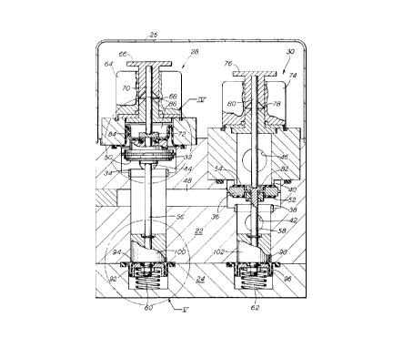
A preferred construction of brake valve 14 may be
described with reference to Figure 2. As can be seen,
valve 14 includes a housing block 22 defining various
fluid ports. A bottom plate 24 is connected to
housing block Z2 to facilitate assembly of the
internal valve components. A cover 26 may also be
provided to enclose the upper portion of valve 14
during use.
Valve 14 includes two internal valves, controlled
by respective solenoids 28 and 30. For purposes of
explanation, the two internal valves will be referred
to as the "left valve" and the 'rright valve" as seen
in the view of Figure 2. In this case, the left valve
includes a valve element 32 axially movable into and
out of engagement with valve seat 34. The right valve
includes a valve element 36 axially movable into and
out of engagement with opposed valve seats 38 and 40.
For reasons that will become apparent from the
discussion below, valve seats 38 and 40 preferably
have approximately the same diameter, and therefore
~ equivalent effective areas.
Referring again also to Figure 1, housing 14
defines a supply port 42. In use, supply port 42 is
connected to conduit 16, thereby establishing fluid
communication with rese~voir 10. A delivery port 44
is similarly connected to conduit 18 for providing
fluid communication with brake cylinder 12. An
exhaust port 46 is likewise connected to exhaust pipe
20. Fluid communication between the left and right
valves is provided by an interconnecting conduit 48,
which may thus itself be considered a port for the
~ ~ 2182462
respectlve internal valves.
It will be appreciated that housing 22 defines
two fluid flow paths through its interior. The first
such flow path extends from supply port 42, along
interconnectlng conduit 48, to delivery port 44. The
second such flow path e~tends from delivery port 44,
back along interconnecting conduit 48, to exhaust port
46. The combination of these flow paths and the
configuration of the left and right valves permits the
multiple states of fluid transfer described above.
For example, the delivery state is achieved with
valve elements 32 and 36 in their respective "at rest"
positions, as shown in ~lgure 2. Pressurized air
entering supply port 42 will be conducted along the
first fluid flow path directly to delivery port 44.
The illustrated design thus causes brake application
in the absence of an actuation signal at solenoids 28
and 30, as desired in many applications.
The exhaust state is achieved in the illustrated
design by the actuation of solenoid 30. Specifically,
actuation of solenoid 30 causes valve element 36 to
engage valve seat 38. In so doing, valve element 36
moves from its "at rest" engagement with valve seat
40. As a result, pressurized air within the brake
~ cylinder will be conducted along the second fluid flow
path from delivery port 44 to exhaust port 46.
The lap state is achieved by actuation of
solenoid 28. Specifically, actuation of solenoid Z8
will cause valve element 32 to move from its "at rest"
position into engagement with valve seat 34. When
valve element 32 is engaged in this manner,
pressurized air already present in the brake cylinder
will be trapped. As such, the braking force applied
by the associated brake will remain substantially
constant.
:
~ 2182462
Referring now also to Figures 3 through 5, the
construction of the internal valves will be described
in detail. Each of the valve elements 32 and 36 are
configured in this case as a disc having a elastomeric
ring mounted thereon for engaging the associated valve
seat and providing an effective seal therewith. Thus,
valve element 32 has a single elastomeric ring 50
mounted on its bottom side for engaging valve seat 34.
Similarly, valve element 36 has two elastomeric rings
52 and 54 mounted on its respective sides for engaging
valve seats 38 and 40.
As can be seen, valve elements 32 and 36 are
themselves mounted on respective valve stems 56 and
58. Solenoids 28 and 30 function to move valve stems
56 and 58 axially downward (in the reference frame of
Figure 2), whereas springs 60 and 62 urge valve stems
56 and 58 axially upward. In the illustrated
embodiment, springs 60 and 62 are chosen such that
they provide sufficient spring force to return
respective valve elements 32 and 40 to their "at rest"
positions when solenoids 28 and 30 are deactivated.
Spring 62 should also provide sufficient spring force
to ensure an effective seal between elastomeric ring
54 and valve seat 40.
~ Solenoid 28 includes a stationary coil portion
64, a moveable armature 66 and a stationary pole piece
68. A push pin 70, extending through pole piece 68,
is attached to armature 66. As shown, push pin 70
engages a stem head 72 located at one end of valve
stem 56. As a result, an electrical current applied
to coil portion 64 will cause attraction of armature
66 to pole piece 68, thereby causing push pin 70 to
axially move valve stem 56.
Similarly, solenoid 30 includes a stationary coil
portion 74, a moveable armature 76 and a stationary
.
~ 2t 82462
pole piece 78. A push pin 80 is provided in this case
to engage a stem head 82 located at one end of valve
stem 58.
As discussed above, fluid pressure within valve
14 will often greatly exceed the axial force that can
be easily produced by a typical solenoid or return
spring. In an unbalanced valve design, a significant
portion of this fluid force will oppose axial movement
of the valve stem. For example, the fluid force may
act on the valve element in a direction opposite that
which occurs when the solenoid is activated, or
opposite the direction of the return spring. The
solenoid or spring may be, unless made very large,
incapable of producing sufficient axial force to
overcome this fluid force.
To cancel the effects of the fluid force, the
left and right internal valves of valve 14 each
include at least one counterbalance assembly.
Preferably, a counterbalance assembly will be provided
for each valve inlet supplying greater than
atmospheric pressure at some time during its
operation. Thus, the left valve will have two (2)
coun~rh~l~nce assemblies, since pressurized air from
both the supply port 42 (through interconnecting
- conduit 48) and delivery port 44 must be balanced.
The right va~ve, on the other hand, may have a single
counterbalance assembly to balance pressurized air
from the supply port 42. Exhaust port 46 may not
re~uire a counterbalance assembly if it exhausts to
atmosphere.
In presently preferred embodiments, the
counterbalance assemblies function to provide a
substantially constant balancing force throughout the
reciprocative stroke of the associated valve element.
In other words, the counterbalance assembly will
21 82462
provide a certain balancing force not only at the end
points of the stroke, i.e., completely closed or
completely open, but at axial locations in between.
As a result, valve 14 is more easily controlled with
less solenoid or spring force than would otherwise be
required.
Toward this end, each of the countPrhAlAn~e
assemblies is preferably constructed having a
flexible, rolling diaphragm supported by a
complementary diaphragm follower. A thin diaphragm is
especially preferred because it contributes relatively
little friction that the solenoid and spring must
overcome. A diaphragm having a thickness of no
greater than approximately 20-30 mils is generally
useful for this purpose.
As shown in Figure 4, the counterbalance assembly
located adjacent stem head 72 includes diaphragm 84
and diaphragm follower 86. Follower 86 is configured
having a cup-shaped lower portion 88 integrally
extending into an a upper flanged rim portion 9o. It
can be seen that diaphragm 84 largely conforms to the
exterior dimensions of follower 86.
During use, diaphragm 84 will maintain a
substantially constant effective area as follower 86
is moved axially with valve stem 56. (The effective
area of the diaphragm may be defined as the diameter
at the location where it folds back onto itself, in
this case directly under rim portion 90 of follower
86.) In order to substantially balance the fluid
force imposed on valve element 32 when engaging valve
seat 34, this effective area is preferably made to be
substantially equal to the effective area of valve
seat 34 (which may be determined from its effective
diameter D).
2~ 82462
Because the effective area of diaphragm 84 will
remain substantially constant as it is moved axially
with valve stem 56 (due to follower 90), the axial
force imposed on diaphragm 84 by the fluid will also
remain substantially constant (except to the extent
that the fluid pressure itself may vary). In this
way, diaphragm 84 wi31 contribute a controlled, upward
balancing force during the reciprocative stroke of
valve stem 56. This is in contrast to many prior art
valve designs in which the effective area of the
diaphragm may vary as the valve stem moves. This
change in effective area may cause a concomitant
change in the force component contributed by the
diaphragm. It will be appreciated that such a varying
force may lead to undesirable operational states in
the valve.
The other counterbalance assemblies of valve 14
function in a similar manner. In this regard, Figure
5 illustrates the lower counterbalance assembly of the
left valve, which includes a diaphragm 92 and a
follower 94. Due to the configuration of follower 94,
the effective area of diaphragm 92 will remain
substantially constant during the stroke of valve stem
56. As a result, a controlled, downward balancing
~ force will be contributed as valve element 32 axially
moves with valve stem 56. Like the upper
counterbalance assembly, the effective area of the
lower counterbalance assembly is also preferably made
to be approximately equal to that of valve seat 34.
As shown in Figure 2, the single counterbalance
assembly of the right valve similarly includes
diaphragm 96 and follower 98. Follower 98 ensures
that the effective area of diaphragm 96 will remain
substantially constant as valve stem 58 is moved.
Thus, this counterbalance assembly will also provide a
2 1 82462
14
controlled balancing force throughout the
reciprocative stroke of valve element 36. In this
case, the effective area is preferably made to be
approximately equivalent to that of valve seat 38 (and
valve seat 40).
The operation of the left and right valves, as
aided by the various counterbalance assemblies, will
now be described. W:ith valve element 32 and valve
element 36 in their respective "at rest" positions,
pressurized air will flow from supply port 42 to
delivery port 44, as described above. This fluid
force will impose a certain axial force on diaphragm
84 in the upward axial direction. However, an
e~uivalent fluid force will also be imposed on
diaphragm 92 in the opposite, downward axial
direction. As such, diaphragm 84 and diaphragm 92
will function to counterbalance one another, as
desired.
The pressurized air from supply port 42 will also
impose a downward axial force on diaphragm 96. In
addition, an upward axial force will be imposed on
valve element 36, as defined by the effective area of
valve seat 40. Because the effective area of
diaphragm 96 and valve seat 40 are the same, however,
~ the fluid forces will be substantially canceled.
Assume now that valve 14 is to enter the lap
state. In this case, valve element 32 will move from
its "at rest" position into engagement with valve seat
34, as described above. Because the effective areas
of diaphragm 84 and diaphragm 92 remain the same
during axial movement of valve stem 56, the fluid
forces which would otherwise oppose axial movement of
valve stem 56 also remain substantially balanced.
This balance will continue throughout substantially
the entire stroke through which valve element 32
21 82462
axially moves.
As valve element 32 engages valve seat 34, a
fluid force will be imposed thereon in proportion to a
pressure difference between supply port 42 and
delivery port 44, as well as the effective area of
valve seat 34. Because diaphragm 84 has the same
effective area as valve seat 34, diaphragm 84 will
oppose the fluid force imposed on valve element 32 by
pressurized fluid entering back through delivery port
44. Similarly, diaphragm 92 will balance the force
imposed on valve element 32 by fluid entering through
supply port 42.
Assume now that valve 14 has entered the exhaust
state. In this case, valve element 32 will be in its
"at rest" position, where diagrams 84 and 92 will
balance each other as described above. In addition,
however, valve element 36 will move from its "at rest"
position against valve seat 40 into engagement with
valve seat 38. As a result, pressurized fluid
entering supply port 42 will impose equal and opposite
forces on diaphragm 96 and the underside of valve
element 36. Again, the fluid force will be
substantially balanced, as desired.
Referring again to Figure 2, the illustrated
construction further includes a cylindrical guide
element lOO mounted to valve stem 56. As shown, guide
element 100 has an outer diameter slightly smaller
than the inner diameter of the interior bore through
which valve stem 56 extends. As a result, guide
element 100 functions to transversely stabilize valve
stem 56 during its axial movements. A similar guide
element 102 is mounted to valve stem 58.
For purposes of further describing the
construction of valve 14, reference is now made to
Figure 3. Specifically, Figure 3 illustrates the
2 1 82462
16
manner in which the various components may be
assembled onto valve stem 56 in the illustrated
embodiment. While only valve stem 56 is shown in this
drawing, it should be appreciated that valve stem 58
may be similarly assembled.
As shown, the first component mounted on valve
stem 56 is follower 86. Next, diaphragm 84 is mounted
on valve stem 56, followed by a backing disc 104.
Valve element 32 and retaining collar 106 are next
lo installed.
Guide element 100 is retained in position by a
snap ring 108. Snap ring 108 is itself maintained in
a groove 110 defined about valve stem 58 at the
appropriate location. After guide element loO is
installed, diaphragm 92 and follower 94 are positioned
on valve stem 56. Finally, a retaining nut 112 is
secured to a threaded portion 114 at the end of valve
stem 56.
It can be seen that the present invention
provides a valve assembly which overcomes the various
disadvantages of the prior art. Because of the
substantial balancing achieved in the valve interior,
the axial forces supplied by both the solenoid and the
return spring can be very small. In fact, the force
~ of the return spring may be limited to the small
amount of diaphragm friction, as well as the force
component necessary to achieve firm engagement between
the valve element and its associated valve seat. The
solenoid should be sized to produce these force
components plus sufficient force to overcome the
return spring.
It should also be distinctly understood that the
teachings of the present invention are not limited to
valves having multiple interior valves, but also
include various singular valve designs. Thus, while
21 82462
preferred embodiments of the invention have been shown
and described, modifications and variations thereto
may be practiced by those of ordinary skill in the art
without departing from the spirit and scope of the
present invention, which is more particularly set
forth in the appended claims. In addition, various
embodiments of the invention may be interchanged both
in whole or in part. Further~re, those of ordinary
skill in the art will appreciate that the foregoing
description is by way of example only, and is not
intended to be limitative of the invention so further
described in such appended claims.