Note: Descriptions are shown in the official language in which they were submitted.
218278~
woss/2~0s pcTlGBssl~35o
WCUND H~LING MATERIAL
TECHNICAT Fl~n
The present invention relates to a device for use in
promoting wound healing (whether the wound be the result
of an accident,~a surgical wound or a wound caused by
disease) which allows guided tissue repair so as to
encourage the regeneration of tissue of normal function
and morphology.
BACKGROUND
The body's capacity to repair itself after
accidental wo~ g or after surgery is often defective
because the tissues rebuild with an incorrectly oriented
or even with an unoriented structure, or because cells of
one type push cells of other types away from their
correct positions within the tissue. For example,
fibroblasts often form fibrous tissue during wound
healing that blocks nerve cell regeneration, or prevents
the correct connection of nerves to prosthetic devices.
In a similar way, when gums heal after tooth replacement,
competition occurs between epithelia and fibroblasts.
Problems may also arise with the healing of tendons that
have been cut or damaged. Thus, synovial cells become
unoriented and stic~ to epithenon cells, with the result
that tendons after healing may adhere to the wall of the
2182784
WO 95/2230S PCI/GB95/00350
synovial canal within which they lie. Furthermore, there
is difficulty in rejoining the ends of the tendons
themselves, since the t~nAon is under tension, with the
result that a gap may exist between the ends of the cut
or torn t~n~on. In order to achieve a satisfactory
repair, this gap has to be bridged by correctly aligned
epithenon cells. Even dermal wounds often repair with an
incorrect structure, which may result in pain or
disfigurement. In the same way, inappropriate cell
formations may occur during the healing of abdominal or
cardiovascular surqical wounds.
A further problem in the healing of wounds, is the
possible introduction of inappropriate cells, such as
inflammatory cells into regions of the wound. For
example, the aCcll~tllation of inflammatory cells in
synovial sheath and epitenon in the healing of rat flexor
tendons is described by B. Wojciak and J.F. Crossan,
Clin. Exp. Immunol. 1993; 93: 108-114.
Our European Patent Application EP84308230.6
disclosels the location of biological cells in a
predetermined spatial disposition on a solid non-
biological substrate, by providing the substrate with a
plurality of surface discontinuities defining cell
adhesion enhanced and/or cell-adhesion orienting zones,
for example grooves or ridges. However, it does not
address the issue of wound healing. More recently, the
218~78 1
wogsn~os PCT/GB9S/~350
microt~ Laphical control of cell behaviour by the use
of a ~ substrate has been described by Clark et
al., Development 108: 635-644 (1990).
The use of laser holography and microelectronic
t~hni ques to make ultrafine gratings and the behaviour
of these gratings in aligning cells is described by Clark
et al Journal of Cell Science 99; 73-77 (1991).
Whilst these publications describe the orientation
of cells in vitro, they do not provide a solution for the
production of orderly cell formations during healing of
wounds in vivo. It is an object of the present invention
to address this problem.
SUMMARY OF THE lNV ~:N'l lON
Generally 5p~Akin~, the ~rescnt invention is h~
on the use of means for guiding tissue regeneration
during wound healing, thereby encouraging the
regeneration of tissue of normal function and morphology.
The present invention provides use of a device in
wound healing, the device comprising a substrate formed
of a biologically-acceptable material, the substrate
having thereon means capable of orienting cell growth.
In another aspect, the invention provides the device
itself for use in wound healing.
In a further aspect the invention provides a method
of healing wounds in a patient by providing the device in
21827~
WO 95/22305 PCr/GB95/00350
the wound or adjacent the wound site. In this way the
orderly growth of cells during the wound healing process
is promoted, such that the cellular ordering of the
healed wound more closely matches the original cell
structuring and function.
The device may be a biodegradable device comprising
a biodegradable substrate which becomes resorbed in vivo
and effectively disappears from the wound site.
However, in other instances the device may be non-
resorbable such as in the case of permanent implants
where wound healing is required. Implants including
metallic, plastics and ceramic implants are used in
connection with joint repair, for example, hip joint
prostheses. Such implants may be provided with the cell
growth orienting means integrally formed or provided on
the surface of the implant itself; or the cell growth
orienting means may be on a separate substrate sheet
provided on the surface of the implant (such as by
wrapping around the implant or adhering thereto). The
substrate sheet may be resorbable or non-resorbable.
T~e term "wound" is to be understood in a broad
sense as covering wounds made as a result of an accident,
as a result of surgery or dentistry or in relation to
wounds caused by disease. Surgical wounds include those
made for cosmetic purposes and also for the repair of
genetic malformations, such as cleft palate or
218278~
wossn~os pcTlGBs
gargoylism. Wounds may also be pro~l~ce~ by various
disease states or as a result of infectious organisms,
such as for example, ulcers or resulting from
septicaemia. A wound will generally comprise a
discontinuity in an existing tissue, and healing requires
the growth of cells from the edges of the tissue such as
to fill the discontinuity. Nothing in the prior art
indicates that growth of cells from existing tissue to
heal a wound could be promoted by use of the present
device.
Thus, it is surprisingly found that the use of a
material having cell growth orienting means that may
orient cell growth, shape and extension, can be effective
in assisting orderly wound healing. It may also prevent
cell penetration into inappropriate regions, and prevent
the formation of adhesions. The presence of the cell
growth orienting means at least during the initial stages
of wound healing, may be sufficient to initiate cell
growth patterns of adhesive cells which assist orderly
cell arrangements; whether or not (in the case of a
biodegradable substrate) that substrate is present
throughout the entire process of wound healing. In that
case, it is generally advantageous that the substrate
biodegrades and disappears from within or around the
wound site prior to the completion of the healing
process, so that the substrate itself does not occupy
w095t2230s 2 1 8 2 7 8 4
space which should otherwise be filled with cells, and
thus interfere with the wound healing. It has been found
desirable that a biodegradable substrate should degrade
completely within 2 to 14 days, though this may ~opon~ on
the severity of the wound and the speed of healing in the
particular wound type. It may also ~Pp~n~ on the
physiology of the particular patient.
~ he mech~niçm of biodegradation should rely on
subst~es naturally present in the body at or near a
wound site. Usually, biodegradation is brought about by
enzymes, which may be free or attached to the surfaces of
cells, or by the release of oxidative species via the
cells. Materials which are biodegraded by other
mech~niC~s~ for example by bacterial action, involving
species not normally present in the body are unsuitable.
A wide variety of biodegradable biologically-
acceptable materials are known and the skilled man will
choose a suitable material, which is able to carry the
nececs~ry cell orienting means and have a suitable
biodegradation time in vivo. Suitable polymer materials
include polylactic acid homopolymers, polyglycollic acid
homopolymers, lactic acid-glycollic acid copolymers,
polydioxanones, polyoxalates, polydiox~one-glycollic
acid copolymers, polylactcnes (such as polymers of
caprolactone and valerolactone), polyhydroxybutyrates,
polyhydroxyvalerates, polyorthoesters, polyanhydrides,
2182781
w09Sl2~0s pcTlGB9s
polypeptides, polyvinylalcohols, polyphosphazenes, and
natural polymers (e.g. collagen and polysaccharides). In
the case of homopolymeric materials, corresponding
copolymers with other such materials may also be used.
A detailed t~;-cc~Ccion of biodegradable polymers is given
in S.J. Holland and B.J. Tighe "Biodegradable Polymers",
Advances in Pharmaceutical Sciences, 1992, plOl-164.
In particular, materials commonly used to produce
dissolvable sutures may be suitable. Reconstituted
collagen may be employed as the substrate, though its
uneven consistency may inhibit the application of
suitable microtopography.
Non-biodegradable medical grade polymers include
polyamides, polyethylenes, polypropylenes,
polycarbonates, and polyesters.
For sheet-like substrates, the thic~n~ss may be up
to 250 microns, but is preferably in the range 50-100
microns. The thickness is a factor which determines the
flexibility of the device. The time for biodegradation
to occ~r will also depend on the thickness of the
substrate.
In a particular embodiment, the device has a
flexible nature, which allows it to be inserted into a
wound. Three-dimensional tissue repair may be achieved
by imparting a three-~ ncional configuration to the
substrate. In the case of a substrate in sheet-form, it
21827~
wossn~os pcTlGB9sl~3so
can be folded, rolled, formed into a spiral or st~ck~
structure, or formed into any other shape appropriate to
a specific anatomical site or surgical procedure. In
particular, the substrate may be in the form of a sheet
which has been folded. The substrate may be folded once
or a number ~ of times into a concertina-like
configuration. Thus, a flexible sheet conformation is
particularly useful for insertion into a wound.
Flexibility in the substrate also allows it to be wrapped
around a structure such as a ligament, tP~on, muscle,
blood vessel or other elongate structure which requires
repair.
The device may also be provided in the form of a
tube, optionally a longit~t~ ly split tube, for fitting
into or around a wound site, particularly where a
substantial gap in the wound exists which requires to be
filled with cells during the wound healing process. For
instance, a tube may be positioned within the wound to
promote cell growth at the centre of the wound; and a
tubular-substrate may be wrapped around the outside of
the wound, in order to promote correct cell growth in the
outer regions of the wound. Thus, in the repair of a
tendon, it may be advantageous to provide a central tube
within the wound between the separated ends of the
tendon, together with a tubular sheet of the substrate
wrapped around the tendon and tièd off around each end
218278~
woss/2230s pcTlGBss
with a conventional suture.
A particular use of biodegradable (i.e. resorbable)
materials is to form a spacer(s) to hold the device into
a configuration which is suitable for packaging, surgical
manipulation and implantation; prior to biodegradation
thereof in vivo. In one such case, part of the wound
healing device may be biodegradable whilst the rem~in~er
is formed of a non-degradable material.
The cell growth orienting means may direct the
orientation and CO..~LO1 the speed of cell movement, and
can be in the form of a suitable microtopography and/or
suitable micro~h~m;ctry to influence Le~lo~th.
Suitable microtopography to provide orientation of cell
growth is already known, as described previously. It may
be effective to control cell orientation, cell shape,
speed of cell movement, and plane of cell division. For
application to the healing of wounds, the microto~u~L~phy
is preferably in the form of a series of peaks and
troughs e.g. parallel grooves (and/or ridges). Sharp
edged Substantially rectangular-section grooves are
particularly useful. Preferably, the yl~oves have a
width of 1-10 microns. The width and depth of the
grooves is to some extent determined by the nature of the
cells which are to be grown. Preferably, the depth of
the grooves is from 0.3 to 5 times the average width of
the cell when the cell is positioned on a flat surface.
218278~ -
- woss/2230~ PCTIGB95/00350
Practically speAki~, this means that the depth of the
groove is generally in the region of 1-10 microns also.
Preferably, the ratio of the width of the groove to its
depth (i.e. the aspect ratio) is in the region ~.S to 2,
preferably substantially 1:1. Generally, the spacing
between the groove edges will be of the same order as the
width of the grooves themselves, that is to say 1-10
microns. The groove spacing from centre to centre is
generally 2-20 microns. One particular preferred
embodiment ~hat has been used for epitenal cells and
muscular cells has a groove width 5 microns, groove depth
3 microns and groove spacing (centre to centre) of 10
microns. ~i.e. 5 microhs between ~.oove edges). Groove
size may be ~hoC~ to preferentially exclude one cell
type (e.g. inflammatory cells) from a specified region
and to favour another cell type. Macrophages may be
guided by grooves which are of the order of nanometers
deep and may be preferentially withdrawn from a site
(e.g. a prosthesis) by appropriate choice of groove size.
Another microtopographical structure which may
provide the desired degree of cell growth orientation is
in the form of a series of rounded protrusions or bumps
arranged in a regular array. Preferably the array is a
square array (i.e. the protrusions lie on a regular
square grid). The cells then tend to grow along the
valleys defined between adjacent rows of protrusions.
218278~
woss/2~0s PCT/GBss/~350
11
However, other cell growth orienting arrangements
may be used d~p~n~inq on the desired healing growth
patterns. These may include circular or serpentine
patterns. Spiral patterns may be used for specialised
pU~ , since cells growing on a spiral tend to migrate
to the region of~lowest curvature. This allows an area
free of cells or reduced in cell number to be provided in
the centre of the spiral.
The microtopographical pattern may be applied in a
manner already disclosed in the prior art, and is
preferably achieved by embossinq directly onto the
substrate, for example by passing the substrate between
the nip created between an embossing roller and a smooth
roller. However, the pattern may be applied to both
faces of the substrate by the use of a pair of embossing
rollers, if desired. The pattern applied to the two
faces may be the same or different.
Embossing of the substrate may be carried out using
dies or rollers which have been manufactured using
photolithography or electron beam lithography, followed
by etching and electro-plating.
It is also possible to orient the cell growth by
means of microchemistry, that is to say by chemically
providing lines of preferred cell growth on the
substrate. Suitable materials for promoting cell
2182784
W09s~05 PCT/GB95/00350
adhesion and thus orientation are disclosed in patent
specification E284308230.6. However, the preferred
method according to the present invention is to provide
strips of cell-adhesive proteins or protenacious
material, optionally with layers of specifically non-cell
adhesive stripes between.
The device may be surface treated in order to
achieve bio-burden control, or modification of the
surface chemistry thereof; for example by the use of
oxygen plasma tech~i ~ues.
The device of the present invention is nPcoccArily
formed of biologically acceptable material, and can, of
course, be sterilised by known methods, e.g. ethylene
oxide, gamma irradiation, or oxygen plasma etching.
DETAILED DESCRIPTTON OF YK~ KK~:V EMBODIMENTS
F~ho~iments of the present invention will now be
described by way of example only.
EXAMP~ 1 (embossinq biodeqradable ~lastic)
(a) Preparation of stamping master formed of polyimide
deposited on a plating base.
Onto a glass plate, a 0.1 um (micron) coating of
nichrome was deposited by electron beam evaporation in
2182784
WO9S12~05 pcTlGBssloo3so
vacuum to form a plating base. Then a 7um coating of
polyimide was put onto the nichrome by spin-coating, and
the polyimide fully cured (by a series of bakes,
fi~ichi~g at 300C.) Alternatively photoresist may be
used in place of the polyimide. Onto the cured
polyimide, a 0.1~m coating of aluminium was deposited by
thermal evaporation, and onto this a 0.5um layer of
positive photoresist was deposited. The photoresist was
exposed using W light to a pattern of 10um lines, lOum
spaces covering a 10 by 10 mm area by contact printing.
The latent image in the resist was developed in resist
developer and the resulting relief pattern in resist was
used as an etch resistant mask during etchinq of the
aluminium in a wet etch bath (consisting of ortho-
phosphoric acid, nitric acid and water). This aluminium
pattern was used as a oxygen-resistant mask in su~sequent
reacti~e ion etching of the polyimide in oxygen. In this
step, oxygen at a flow rate of 20sscm, and 20mT pressure
was ionised in a 100W rf 13.6 MHz AiC~h~rge. The plasma
etches Yertically into the polyimide, and the etching
stops on the underlying nichrome layer. After stripping
of the aluminium mask in aluminium etch, the structure i5
ready for electroplating.
(b) Making of stamp
The structure was placed in a nickel plating bath,
21827~
- woss/2~0s pcTlGBss
the plating base constituting one electrode and a nickel
sheet the other electrode. The plating bath was Lecto-
nic obtained from Ethone-omi. The plating bath was made
up of nickel sulphate plating solution, an activator, a
wetting agent and an adhesion agent following the
manufacturer's i~nstructions. Nickel was deposited to a
thic~ecc of SO to 70um, at a current density of
20mA/cm2. The nickel shim (stamp) was removed from the
glass plate with the aid of a scapel.
(c) ~rhoCcing of plastics sheets
A biodegradable poly-p-dioxanone plastics from
Ethicon Inc., known as Ethicon PDS (trademark), was
melted at 110C and cast into a glass petri dish. The
film was removed from the glass by cutting and peeling,
and placed in a press with the stamp on top of it. The
press was heated to 100C and a force of 5kN applied.
The plastic film was embossed to a depth of 3-4um and was
easily removed from the stamp.
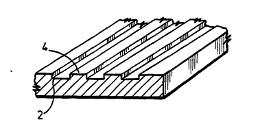
Figure 1 shows a fragment of the embossed sheet to
an enlarged scale, comprising grooves 2 of width lO~m
separated by 2ands 4 of width lO~m.
wo sS/223os 2 1 8 2 7 8 ~
pcrlGBss
t~ 2 (Cell ~reDaration and qrowth)
(i) Baby Hamster Kidney (BHR) cells were cultured until
confluent, then trypsinized, centrifuged and plated onto
the embosse~l structured surfaces, and observed as
follows.
The BHR cells (BHR21 C13) cells were cultured in
BHR21 culture medium (a modified minimum essential medium
supplemented with 0.22% bicarbonate, 10% calf serum, lOS
tryptose broth, 2.85mM glutamine and antibiotics) in
75cm3 polysLy.ene culture flasks. When the cells became
confluent they were trypsinised with trypsinversene
solution at a trypsin activity of 250 BAEE unit/ml in
0.5mM EDIA in Hanks saline (free of calcium and magnesium
ions) for S min at 37C.
Then the cells were spun at 1400rpm and resuspon~P~
in S ml culture medium, kept at room temperature for 10
mins and then spun again. The pellet was resuspended in
BHK 21 medium and kept in sterile conditions until used.
Ce~,ls were plated onto 33mm diameter Petri 1; 5hPC
containing the embossed biodegradable plastics sheets or
glass coverslips (controls) at a density of 2.105
cells/ml and incubated overnight at 37C. The cells were
PY~ined in an optical microscope. The degree of
alignment of the cells to the direction of the grooves
was very marked, alignment ~eing essentially complete.
218278~
W095/2~05 PCT/GBg~/~350
16
The morphology of cells was notably different from cells
on plain surfaces; the cells being longer and thi n~er.
(ii) In another experiment human endothelial cells
(GHTEN line) which had been maint~ in Hans FlO
supplemented with 3% Foztal calf serum and supplements
were plated onto the emhoc~ed plastics sheets. These
endothelial cells are present in the walls of capillary
blood vessels. These human endothelial cells showed good
alignment along the direction of the grooves in the
embossed plastics sheet, and moved more rapidly along the
grooves than the other cells.
Minimum essential medium (MEM), Hanks saline and
Hans FlO are well known media whose composition is
defined in s~ rd text books on cell culture methods
(e.g. Freshney R. Ian. "Culture of Animal Cells: A
Manual of Basic Technique" (1987) published by Alan R.
Liss, Inc. (NY), Second Edition).
EXAMPLE 3 (Rat Tendon)
We used fused silica substrata with multiple grooves
in tendon organ culture. The dynamics of tendon healing
was co~r~red on plain and patterned substrata. The
sensitivity of epitenon cells to tu~G~Laphical features
2182784
- wo95~05 pcTlGBss
17
was also studied.
(i) Substratum patterninq
Fused silica samples (Multi-lab) were cut into 2Smm2
by lmm thick samples. The silica was cleaned by 50~ki~
in a solution of~ 3:1 sulphuric acid: hydrogen peroxide
for 5-10 min at 60-C followed by rinse in R.O. water,
then blow dried with filtered air. The silica was coated
with photoresist by spinning at 400 rpm for 30 s
followed by a soft bake at 90-C for 30 min. This gave a
resist thiC~n~CC of 1.8~m. The resist was then patterned
by exposing to u.v. light, through a chrome mask
patterned with the required grating pattern, using a mask
aligner (HTG) for 10 s. The exposed resist was developed
off by immersing the sample in a solution of 1:1 Shipley
developer R.O. water for 65-75 s followed by a rinse in
R.O. water, then blown dry.
The samples were dry etched in a RIE Unit (Plasma
Technology). After etching the residual resist was
removed~ and all samples blanket etched for 1 min.
(ii) Rat Tendon Or~an Culture
Flexor t~n~on~ were isolated from the middle digit
of the hind paw of male Sprague Dawley rats. Twelve 8-
weeks-old rats were anaesthesized using halothane.
Synovial sheath was removed and the tendons were divided
218278~
WO9S12~05 PCT/GBsS/~3s0
and placed on to plain and patterned fused silica
substrata (grooves 5~m deep, 10~m wide) so that the gap
between two tendon ends was 0.5mm wide. Tendons were
placed in parallel to the direction of the grooves and
pressed with a clean coverslip. Tendons were incubated
in BHK culture~ medium (20mM HEPES buffered Glasgow
modified MEM (Gibco BRL, Life Technologies, Paisley, UR))
supplemented with 0.5% bicarbonate, 10% foetal calf serum
(Gibco), 10% tryptose broth (Gibco), 285 mM glut~inP,
antibiotics, for 3 weeks. The medium was changed every
48 h. After 3 and 5 weeks tendons were used for frozen
sections and histological st~ining. Some of the healing
t~n~ons were studied under a light sc~ ng confocal
microscope.
On plain substrata, healing did not occur over a
period of 8 weeks. During this time proliferation of
epitonen cells occurred on the tendon surface close to
the divided tendon ends. The epitonen layer thickened to
become 3-6 cells thick. These proliferating cells then
migrated round the surface of the divided end so that
their long axis lay at right angles to the long axis of
the tendon. There was no evidence of significant
migration across the gap to restore continuity between
the tendon segments. Similarly, extracellular matrix was
laid down in the same orientation so that the tendon ends
became rounded off.
218278~
wossl2~05 PCT1GB95100350
In conL~ast, when tendon segments were placed
together in the same orientation as the grooves on the
microfabricated substrata according to the invention,
reconstitution of the tendon occurred within 8 weeks in
most experiments. The tendon ends became bullet-shaped,
rather than being rounded off and thus approached one
another. A considerable degree of epitonen proliferation
occurred close to the site of the division, but instead
of migrating over the surface of the end of the tPn~o~,
they formed~ a highly cellular advancing front which
started to fuse with similar tissue from the opposite
tendon at about 3 weeks. Over the next 3 weeks
practically all of these advancing cells disappeared,
leaving a loosely bound mass of extracellular matrix
aligned in the long axis of the tendon so that continuity
was restored. The histology of the restored ~Pn~on was
nearly normal.
(iii) Rat EDitenon Cell Culture
Ra~t epitenon fibroblasts were isolated from rat
flexor tendons of male Sprague Dawley rats. Briefly, in
step l, the synovial sheath was removed by incubation of
tendons in 0.5% collagenase (Clostr~diopeptidase A; EC
3.4.24: sigma Chemical Co. Poole, UK) for l0 min at
37 C.
In step 2 tendons were incubated in trypsin/EDTA
218~784
- W095/2~05 PCT/GB95/~350
solution (trypsin, 300 BAEE (N ~-benzoyl-L-arginine ethyl
ester) U/ml; EDrA, 0.001 m ED$A) for ~.5, at 37 C then
the released cells were suspended in BHX21 medium and
centrifuged at 200 g for 6 min. Cells were then
resusp~nA~ in the culture medium (BHR21) and plated into
25 cm2 Falcon culture flas~s at cell density 2 x 10⁵
cells/ml. For experiments they were used between 15 and
25 passages.
For experiments epitenon cells were plated on to
plain and patterned fused silica substrates at cell
density 2x10⁵ cells/ml. After 24 h cells were washed in
serum-free Hank's balanced salt solution and fixed in 4
formaldehyde in phosphate-buffered saline (PBS) for 5
min. Then the cells were washed again in PBS, st~in~ in
Kenacid blue (Sigma, UR) (0.1% in water/methanol/acetic
acid, 50:50:7) for 10 min, and analysed using an image
analysis system.
Cell spread area, elongation and orientation
(aliqn~nt to the groove direction) was measured in
epitenon cells cultured on plain and patterned substratum
with varying groove depth and width. ~his study has been
done to establish the sensitivity of epitenon cells to
topographical features and find groove parameters that
create the best conditions for the guidance of tendon
cells. The guidance of epitenon cells was compared to
the guidance of BHK cells. Although the two cell lines
218278~
woss~os PCT/GB9S/00350
were obt~in~ from different species, they represent cell
of the same type (fibroblasts) and size (sprP~ing area
2800+ 1200~m2).
Epitenon cells were well guided by multiple grooved
substrata. They responded to tu~o~ aphical features by
a substantial elongation. Their elongation did not
depend on groove width but showed some dependence on
groove depth (one way analysis of variance, p<0.01). The
best elongation was achieved for 2 and S~m deep grooves.
Elongation of BHR cells ~Pp~P~ both on groove depth and
width. Epitenon cells were significantly better
elongated than BHK fibroblasts on shallow grooves 0.5 and
l~um deep (p<O.OS).
Epitenon cells were very well oriented on all kinds
of grooved substrata, although a decrease in cell
orientation was seen for cells grown on shallow grooves,
O.5~m deep. This is documented by low variance in the
tested samples. BHK cells were well oriented by grooves
2 and S~m deep but less oriented by y~ooves 1 and 0.5~m
deep. Vaiance for BHK cells was higher than for epitenon
cells on all kinds of patterned substrata which shows
that epitenon cells are more sensitive to topographical
features than BHK fibroblasts.