Note: Descriptions are shown in the official language in which they were submitted.
~182B37
- 1 - 58,249
TRANS~:R SWITCH SYSTEM WII~I SUBNETWORK
BACKGROUND OF THE INVENTION
Field of the Invention
This invention relates to transfer switch systems for switching between
alternate power sources for loads connected to a load bus and in particular to such a
system including a communications network for coordinating transfers between sources
with operation of the loads.
Background Information
Transfer systems for supplying alternate electric power sources to
specified loads are well known. Often such systems provide power from a commercial
power source and an auxiliary power source such as a local, engine driven generator.
Such transfer systems are widely used in applications such as, for example, hospitals,
computer installations and industrial processes which require continuous power. Many
of these transfer switches effect an open transition between the two power sources.
That is, the load bus is disconnected from the one source before it is connected to the
other source in order to avoid the problems associated with interconnection of
unsynchronized sources. This results in interruption of power to the loads. Often the
auxiliary power source is not capable of supplying the large in-rush currents associated
with simultaneous reenergization of a number of loads such as motors. Typically in
such a situation, the loads are reenergized sequentially. The transfer switch includes
a separate timer connected by separate wiring to each load. There is no indication to
the transfer switch that the loads have responded to the restart signal.
Switching between power sources with an open transition creates special
problems when the loads include elevators. Typically, codes require that the elevators
- 2182837
- 2 - 58,249
be parked at a floor with the doors open before a discretionary transfer between power
sources is made. The usual solution is to send a signal to each elevator over separate
dedicated leads commanding the elevator to park with its doors open. The transfer
switch delays the transfer for a period of time presumed to be long enough to permit
5the elevators to comply. There is no indication that the elevators have responded.
Many utilities today offer preferential rates to customers who agree to
terminate or reduce power usage within a specified time of receipt of notice of the need
for a power reduction. Typically, this notification is processed manually to implement
the power reduction.
10There is a need for an improved transfer switch system with improved
coordination between the transfer switch and the loads.
There is also a need for simplifying and control of the loads by the
transfer switch and making it easier to accommodate different load configurations.
There is also a need for providing feedback to the transfer switch of the
15response of the load to commands from the transfer switch especially where the loads
are elevators.
There is also a need for an arrangement for automatically responding to
notice from a supplier of commercial power to reduce power usage in order to take
advantage of preferential rates.
20SUMl\~ARY OF THE INVENT~ON
These needs and others are satisfied by the invention which is directed
to a transfer switch system for selectively providing power to a plurality of loads on
a load bus from alternate power sources having improved means coordinating transfer
between the power sources with operation of the loads to which power is provided.
25A controller selectively operates switches to transfer from one power source supplying
power to the loads to the other power source. Following a transfer which causes the
loads to become deenergized, the controller sends separate messages spaced in time
over a communications network to remote input/output devices associated with each of
the loads to sequentially restart the loads. Preferably, the remote input/output devices
30send messages back to the controller over the communications network when the
associated load has restarted.
When the loads include elevators, the controller sends a prepare to
transfer message to the remote input/output devices associated with each of the
218~837
3 58,249
elevators, directing the associated elevator to assume predetermined conditions such as
stopping at a floor with the doors open. The remote inputloutput device then sendS
a return message to the controller indicating that the elevator has assumed the
predetennined conditions.
As another aspect of the invention, when one of the power sources is a
commercial power source, a station responsive to a remote signal from the commercial
power company directing a reduction in the use of commercial power sends a transfer
message to the controller which causes the controller to transfer from the commercial
power source to the other power source.
BRIEF DE~,CRIPIION OF THE DRAW~GS
A full understanding of the invention can be gained from the following
description of the preferred embodiments when read in conjunction with the
accompanying drawings in which:
Figure 1 is a block diagram of a transfer switch system in accordance
with the invention.
Figure 2 is a flowchart of a routine utilized in the implementation of the
invention.
DESCR~PTION OF THE PRE~ERRED EMBODIMENT
Figure 1 illustrates a power distribution system 1 in which a transfer
switch system 3 in accordance with the invention controls connection of either a first
power source 5 or a second power source 7 to a load bus 9 supplying power to a
number of loads 11~ - lln. The transfer switch system 3 includes a first switch 13
for connecting a first source 5 to the load bus and a second switch 15 for connecting
the second source 7 to the load bus. A controller 17 monitors the first source 5 and
second source 7 through sensors 19 and 21, respectively, and operates the switches 13
and 15 to selectively connect one of the sources to the load bus 9, as is known in the
art. For instance, where the first source 5 is a commercial power source and thesecond source 7 is an auxiliary power source having an engine driven generator, the
controller 17 can designate the commercial power source 5 as the preferred powersource which will be connected to the load bus 9 as long as the monitored parameters
of the commercial power source are within prescribed ranges. If the commercial
power source does not remain within the prescribed limits, or for test purposes, or
other reasons to be described, the commercial power source 5 can be disconnected
- 2182837
4~ 58,249
from the load bus 9, and replaced by the auxiliary power generator 7. As mentioned,
transfer from the commercial power source S to the auxiliary power source 7 is
effected by an open transition. This te-llpoldly loss of power to the load bus causes
the loads to drop out. As the auxiliary power source 7 does not have the capability to
support the in-rush current of starting all of the loads 11 simultaneously, the controller
17 sequentially restarts the loads. In order to accomplish this, the controller 17 has a
microprocessor 23 which generates separate start messages for each of the loads 11l -
lln. A communications unit 25, which for example can be combined with the
microprocessor 21 on an integrated circuit chip 27 such as the type described in U.S.
Patent No. 5,270,898 interfaces with a communications network 29. The
communications network 29 in turn interfaces with a remote inputloutput device 311 -
31n~ such as an addressable relay, associated with each of the loads 11l - 11n. Each
of the addressable relays 31 includes contact outputs 331 ~ 33n through which the relay
can send signals to the associated load, and contact inputs 351 ~ 35n through which the
addressable relay receives signals from the associated load. The controller 17
communicates with the addressable relay 31 associated with a particular load 11 by
sending a message addressed to the addressable relay over the communications network
29. Return messages from the addressable relay are transmitted over the network 29
back to the controller 17. Thus, when the controller 17 transfers from the first power
source to the second power source, restart messages are generated for each of the loads 11 ~
- l ln . These messages are separated in time by a timer within the microprocessor 23.
These separate messages are addressed to the associated addressable relay which
provides a signal at its contact output which re-starts the associated load. When the
load restarts, a signal is applied to the contact input 35 of the associated addressable
relay which sends the restart message over the communications network 29 to the
controller indicating that the load has responded to the start signal.
In some instances, the load is an elevator such as in the case of load
111. As indicated previously, codes require that the elevator be brought to a floor and
the doors opened thereby creating a predetermined condition before a discretionary
transfer is made which would interrupt power to the elevator. Thus, when a
discretionary transfer is to be made between power sources, either from the source 1
2~ ~2837
- 5 - 58,249
to the source 2 or vice versa, the controller 17 fiLrst sends a message to the addressable
relay 311 associated with the elevator directing that the elevator park at a floor and
open its doors. The floor at which the elevator parks could be the floor at which the
elevator is already located, the next floor at which a moving elevator can stop, or a
design~t~d floor. The addressable relay 311 sends the park signal to the elevator 11
through its contact output 331 When the elevator is parked and its doors are opened,
it generates a signal which is received by the,addressable relay 311 contact input 35~.
The addressable relay 31~ then sends a ready to transfer signal back to the controller
over the communications network 29. When there are a plurality of elevators, thecontroller delays a transfer to another power source until messages are received from
all of the elevators that they are parked and ready for the transfer.
As also mentioned above, many utilities offer preferential rates to
customers who wil~ reduce ~heir power consumption within a predetermined time
interval of receiving notification to do so. This is used by the utility to manage peak
demand. Thus, another addressable relay 31n~l having the signal from the utility
applied to its contact input 35n~1 is connected to the communications network 29.
When the signal to reduce power is received from the utility, this addressable relay
31n~, sends an appropriate message to the controller 17 over the network 29. The
controller 17 can then talce appropriate action. It can make a transfer to the auxiliary
power system, or alternatively it can selectively shed load by sending messages over
the communications network 29 to certain of the addressable relays 31 to disconnect
the associated load 11. Both of these actions may be taken where the auxiliary source
is not able to provide power to all of the loads.
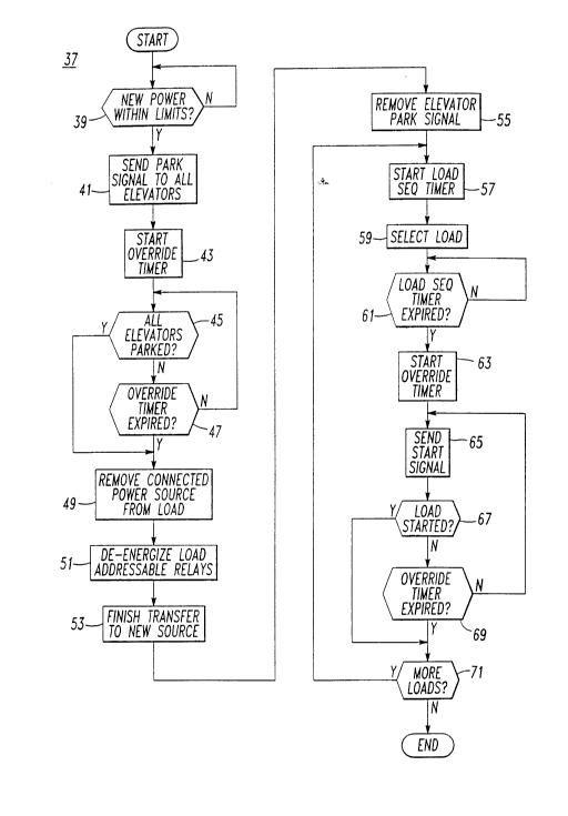
A flow-chart for suitable routine 37 for use by the microprocessor 23 to
implement the above sequencing is illustrated in Figure 2. When the microprocessor
23 determines that a transfer is to be made between two sources, the routine makes
sure at 39 that the new power is within limits. For instance, if a transfer is to be made
to an engine driven generator, it must be determined that the generator has come up
to speed and that the voltage and the frequency are within limits. When the new power
source is ready for the transfer, park signals are sent to the elevators at 41 and an
override timer is started at 43. The elevators report back when they are parked as
- ~182831
- 6 - 58,249
in~ t~ at 45. While it is preferable to have positive feedback that all of the
elevators have parked, the process cannot be disabled if an elevator does not respond.
Hence, even if all of the elevators have not indicated that they have parked with their
doors open, if the override timer expires as indic~t~ at 47, the routine moves on and
S the connP~ted power source is disconnected from the load at 49. The loads are then
disconne~t~d from the load bus through the addressable relays as indicated at 51. The
new source is then conne~t~d to the load bus at 53 and the park elevator signal is
removed from all of the addressable relays at 55.
The loads are then sequentially reenergized beginning with the start of
a load sequence timer at 57. A load to be started is then selected at 59 and when the
load sequence timer is timed-out at 61 an override timer is started at 63 and the start
signal is sent to the addressable relay associated with the selected load at 65. The load
reports back over the network when it has started as indicated at 67. Again, if the
proper response is not received back from the load, the system waits until time out of
the override timer at 69. This starting sequence is repeated until all the loads have
been started as indicated at 71.
While specific embodiments of the invention have been described in
detail, it will be appreciated by those skilled in the art that various modifications and
alternatives to those details could be developed in light of the overall teachings of the
disclosure. Accordingly, the particular arrangements disclosed are meant to be
illustrative only and not limiting as to the scope of invention which is to be given the
full breadth of the claims appended and any and all equivalents thereof.