Note: Descriptions are shown in the official language in which they were submitted.
2182838
EXHAUST STRUCTURE OF OUTBOARD MOTOR
BACKGROUND OF THE INVENTION
The present invention relates to an exhaust
structure of an outboard motor having an exhaust catalyst
means in an arrangement hardly contacting water such as sea
water.
In a recent structure of an outboard motor unit,
a catalyst means is disposed on the way of an exhaust
passage for preventing contamination to atmosphere or water
due to an exhaust gas from the outboard motor.
Fig. 5, which is described hereinlater, is a
partial sectional view of an outboard motor having a
general structure, and referring to Fig. 5, an outboard
motor 1 has an engine 3 mounted to an upper portion of an
engine holder 2 covered by an engine cover 4, and a drive
shaft housing 5 is also arranged at a lower portion of the
engine holder 2. A gear case 6 is mounted to a lower
portion of the drive shaft housing 5.
An exhaust pipe 7 extends downward from the
engine 3 and the exhaust pipe 7 has a downstream side end
to which an exhaust tube 8 is connected. The exhaust tube 8
extends downward in the drive shaft housing 5, and an
exhaust gas from the engine 3 passes through the drive
shaft housing 5 and the gear case 6 and is discharged into
2 182g38
water through an exhaust passage 9a formed around a
propeller shaft 9.
In the above arrangement, a catalyst means 10 for
cleaning the exhaust gas is disposed at a connection
portion between the exhaust pipe 7 and the exhaust tube 8,
for example.
However, in the case where the catalyst means is
disposed in the exhaust pipe extending downward from the
engine, the catalyst is likely contacted to the water in
the drive shaft housing, thus degrading or damaging the
performance of the catalyst. Furthermore, in the described
arrangement, when it is required to exchange the catalyst
with new one at a time of maintenance or inspection, it is
required to disassemble the engine for the exchanging of
the catalyst, thus being troublesome and involving much
time and labour.
SUMMARY OF THE INVENTION
An object of the present invention is to
substantially eliminate defects or drawbacks encountered in
the prior art described above and to provide an exhaust
structure of an outboard motor having an exhaust catalyst
means capable of preventing the catalyst from contacting
water such as sea water.
Another object of the present invention is to
provide an exhaust structure of an outboard motor having a
21~28~
catalyst means and a structure easily attached to or
detached from the outboard motor.
These and other objects can be achieved according
to the present invention by providing an exhaust structure
of an outboard motor having an engine holder, an engine
mounted to an upper portion of the engine holder, a drive
shaft housing mounted to a lower portion of the engine
holder and an exhaust structure connecting an exhaust inlet
opening formed to an upper surface of the engine holder to
an exhaust outlet opening formed to a lower surface of the
engine holder, in an installed state, the exhaust structure
comprising an exhaust port passage extending downward from
the engine and communicated with the exhaust inlet
opening, an exhaust tube extending downward into the drive
shaft housing and an exhaust passage formed between the
exhaust inlet and outlet openings, the exhaust passage
extending horizontally in the engine holder and being
provided with a catalyst horizontally arranged on the way
of the exhaust passage. The catalyst may be disposed in a
catalyst chamber formed on the way of the exhaust passage.
In a preferred embodiment, the exhaust port
passage has an opening in alignment with the exhaust inlet
opening and the exhaust tube has an opening in alignment
with the exhaust outlet opening. A water jacket is
arranged around the opening of the exhaust tube, the
opening of the exhaust port passage and the exhaust passage.
Z18~8~8
Exhaust passage covers for covering the exhaust
passage are detachably mounted to both side portions of the
engine holder. The exhaust passage covers are arranged so
as to divide a portion of the exhaust passage.
According to the present invention of the
structure described above, since the exhaust passage is
formed horizontally in the engine holder and the catalyst
is disposed on the way of the exhaust passage, the water
in the drive shaft housing hardly splashes on the catalyst.
Thus, the possibility of lowering or damaging the function
of the catalyst can be substantially eliminated.
Furthermore, since the water jacket is formed around the
exhaust passage, the temperature of the catalyst can be
stably maintained, thus preventing the cleaning performance
for the exhaust gas from degrading.
Still furthermore, since the exhaust passage
covers are detachably mounted to both the side portions of
the engine holder to partially divide the exhaust passage,
the catalyst can be easily exchanged merely by dismounting
the exhaust passage covers in comparison with a
conventional structure in which the engine must be
dismounted to exchange the catalyst, thus being effective
in operation and maintenance.
The nature and further features of the present
invention will be made more clear from the following
descriptions made with reference to the accompanying
- 2182~38
drawings.
BRIEF DESCRIPTION OF THE DRAWINGS
In the accompanying drawings:
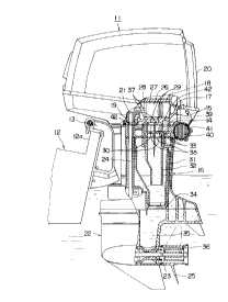
Fig. 1 is an elevational section of an outboard
motor unit provided with an exhaust structure having a
catalyst means according to one embodiment of the present
invention;
Fig. 2 is a plan view, partially in section, of
an engine holder of the outboard motor unit of Fig. l;
Fig. 3 is a side view shown from an arrowed
direction III of Fig. 2;
Fig. 4 is a sectional view taken along the line
IV-IV in Fig. 2; and
Fig. 5 is a partial sectional view of an outboard
motor unit having a conventional structure.
DESCRIPTION OF THE PREFERRED EMBODIMENT
Referring to Fig. 1, showing one embodiment of
the present invention, an outboard motor unit 11 is mounted
to a transom 12a of a hull 12 through a bracket 13, and the
outboard motor unit 11 is provided with an engine holder
14 connected to the bracket 13. An engine 15 is mounted to
an upper portion of the engine holder 14 and a drive shaft
housing 16 is mounted to a lower portion of the engine
holder 14, respectively.
2182~g
The engine 15 is assembled, for example, with a
cylinder head 17, a cylinder block 18 and a crank case 19
and covered by an engine cover 20. A crank shaft 21 is
supported to be rotatable in the crank case 19.
A gear case 22 is mounted to the lower portion
of the drive shaft housing 16 and a propeller shaft 23
driven by the engine 15 is supported to be rotatable to the
gear case 22, and the rotation of the engine 15 is
transmitted to the propeller shaft 23 through a drive shaft
24 connected to the crank shaft 21 and a bevel gear, not
shown to thereby drive a propeller 25 supported to the rear
end of the propeller shaft 23.
A cylinder 26 is arranged in the cylinder block
18 of the engine 15. A piston 27 is inserted into the
cylinder 26 to be slidable therein, and the piston 27 and
the crank shaft 21 are connected through a connection rod
28 to convert the reciprocating stroke of the piston 27 to
the rotational motion of the crank shaft 21. The cylinder
block 18 is formed with an exhaust port extending downward
and communicated with the inside of the cylinder 26, and
the exhaust port 29 is provided with an opening opened
upward to the upper surface of the engine holder 14.
An exhaust expansion chamber 31 having a
cylindrical shape is formed inside the drive shaft housing
16 in a vertical fashion in an installed state so that the
upstream side end portion has a level substantially
- 2l~a3s
coincident with the upper surface of the drive shaft
housing 16. Within the exhaust expansion chamber 31, there
is arranged a cylindrical exhaust tube 32 in a vertical
fashion so that the upstream side end portion of the tube
32 also has a level substantially coincident with the upper
surface of the drive shaft housing 16. The exhaust tube 32
has an opening 33 opened toward the lower surface of the
engine holder 14.
Further, the cylindrical exhaust expansion
chamber 31 also has an opening 34 opened on the downstream
side of the drive shaft housing 16, and the opening 34 is
communicated with an exhaust passage 35 formed in the gear
case 22. The exhaust passage 35 is communicated with water
through an exhaust gas discharge passage 36 formed around
the propeller shaft 23.
Referring to Figs. 1 to 3, inlet openings 37 are
formed to the upper surface of the engine holder 14 so that
the inlet openings 37 are aligned with openings 30 of the
exhaust port 29, and outlet openings 38 are also formed to
the lower surface of the engine holder 14 so that the
outlet openings 38 are aligned with the openings 33 of the
exhaust tube 32. These inlet openings 37 and outlet
openings 38 are connected with each other through an
exhaust passage 39 formed in the engine holder 14.
The exhaust passage 39 extends in a horizontal
direction inside the engine holder 14 and a catalyst
2838
chamber 40 is formed on the way of the exhaust chamber 39.
A catalyst 41 for cleaning the exhaust gas is disposed in
the catalyst chamber 40 horizontally.
A water jacket 42 is formed around the opening 30
of the exhaust port 29, the opening 33 of the exhaust tube
32 and the exhaust passage 39 of the engine holder 14, and
cooling water fills in the water jackets 42.
As shown in Figs. 2 to 4, exhaust passage covers
43 are disposed to both side portions of the engine holder
14 to be detachable and fixed to the engine holder by means
of bolts 44 or the like. The exhaust passage covers 43 are
constructed so as to partially divide the exhaust passage
39.
The present invention will operates as follows.
The exhaust gas discharged from the exhaust port
29 of the engine 15 flows into the exhaust passage 39
formed in the engine holder 14 through inlet opening 37
formed to the upper surface of the engine holder 14. The
exhaust gas entering the exhaust passage 39 contacts the
catalyst 41 disposed in the catalyst chamber 40 to clean
the exhaust gas. The thus cleaned gas is guided from the
outlet opening 38 formed to the lower surface of the
engine holder 14 to the exhaust expansion chamber 31
through the exhaust tube 32. In the exhaust expansion
chamber 31, the exhaust gas is reduced in pressure and in
noise, and thereafter, is guided to the exhaust passage 35
~1~283~
formed to the gear case 22 and then discharged into water
through the exhaust gas discharging passage 36 formed
around the propeller shaft 23.
According to the present invention of the
structure described above, since the exhaust passage 39 is
formed horizontally in the engine holder 14 and the
catalyst 41 is disposed on the way of the exhaust passage
39, the water in the drive shaft housing 16 hardly
splashes on the catalyst 41. Thus, the possibility of
lowering or damaging the function of the catalyst 41 can be
substantially eliminated. Furthermore, since the water
jacket 42 is formed around the exhaust passage 39, the
temperature of the catalyst 41 can be stably maintained,
thus preventing the cleaning performance for the exhaust
gas from degrading.
Still furthermore, since the exhaust passage
covers 43 are detachably mounted to both the side portions
of the engine holder 14 to partially divide the exhaust
passage 39, the catalyst 41 can be easily exchanged merely
by dismounting the exhaust passage covers 43 in comparison
with a conventional structure in which the engine must be
dismounted to exchange the catalyst, thus being effective
in operation and maintenance.