Language selection

Search

Patent 2183106 Summary

Third-party information liability

Some of the information on this Web page has been provided by external sources. The Government of Canada is not responsible for the accuracy, reliability or currency of the information supplied by external sources. Users wishing to rely upon this information should consult directly with the source of the information. Content provided by external sources is not subject to official languages, privacy and accessibility requirements.

Claims and Abstract availability

Any discrepancies in the text and image of the Claims and Abstract are due to differing posting times. Text of the Claims and Abstract are posted:

  • At the time the application is open to public inspection;
  • At the time of issue of the patent (grant).
(12) Patent Application: (11) CA 2183106
(54) English Title: NETWORK PC SUPERVISED ALARM SYSTEM
(54) French Title: SYSTEME D'ALARME ET DE SURVEILLANCE POUR MICRO-ORDINATEURS EN RESEAU
Status: Dead
Bibliographic Data
(51) International Patent Classification (IPC):
  • G08B 13/22 (2006.01)
  • H04L 43/00 (2022.01)
  • H04M 11/06 (2006.01)
  • H04Q 1/02 (2006.01)
(72) Inventors :
  • MURET, MICHAEL A. (Canada)
  • JACKSON, BOB R. (Canada)
(73) Owners :
  • MURET, MICHAEL A. (Canada)
  • JACKSON, BOB R. (Canada)
(71) Applicants :
  • MURET, MICHAEL A. (Canada)
  • JACKSON, BOB R. (Canada)
(74) Agent:
(74) Associate agent:
(45) Issued:
(22) Filed Date: 1996-08-12
(41) Open to Public Inspection: 1998-02-13
Availability of licence: N/A
(25) Language of filing: English

Patent Cooperation Treaty (PCT): No

(30) Application Priority Data: None

Abstracts

English Abstract


A method and system for monitoring equipment in a network environment are provided. Such equipment
could be, but may not necessarily be, computers, printers, monitors, and other computer hardware. The
system incorporates existing network cabling in the building which must contain a plurality of conductors,
of which, at least two conductors must not be utilised by the existing network protocol. The system uses
the two unused conductors to create a current loop which can be monitored from a central location. A
specific resistance is fastened to the monitored equipment, and a voltage comparator at the central location
activates an alarm if the resistance changes. The system is designed so that it can be installed onto existing
network structures using common network patch cables, and without permanently defacing the monitored
equipment.


Claims

Note: Claims are shown in the official language in which they were submitted.


Claims:
1. A computer equipment alarm system which comprises: a dual operational amplifier circuit that
monitors an unbalanced resistor circuit in such a way that the operational amplifiers are both normally
latched to their negative supply voltage until one of the resistances significantly changes; a constant
voltage across the said resistor circuit; one resistor which is part of the resistor circuit, but is permanently
attached to the said computer equipment; two conductors in a network cable which are not used by the
network and connect the single resistor on the said computer equipment to the rest of the said resistor
circuit.

Description

Note: Descriptions are shown in the official language in which they were submitted.


3/G~


Description:
The system utilises current network cabling technology which carries computer network signals to and
from COJIIInllel equipment and a network concentrator. The system injects an alarm signal into the existing
cabling system, near the Conce~ dlUI, on conductors that are normally unused by the computer network.
The alarm signal is terminated at the cv~ ulel equipment so that an alarm is triggered when the collll,ute
equipment is disconnected from the cabling system.
The system is designed to work whether the connected computer equipment is powered on or off, since
there is no electrical connection between the alarm signal and the computer or network.
The system is comprised of three distinct parts: The monitoring panel, the cabling system, and the
equipment interface.

Monitoring Panel:
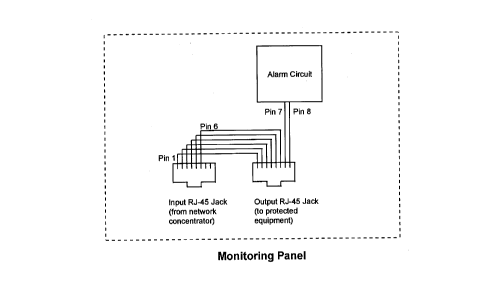
The monitoring panel is connected to the existing network system using standard RJ-45 jacks. For
each piece of equipment that is to be protected, there is an input jack and an output jack on the panel as
shown in Figure 1. The input jack is for the network signal coming and going to the network
concentrator, and the output jack is for both the network and monitoring signals coming and going to
the monitored equipment.
Network concentrators have a single RJ-45 jack for each network device. Without the monitoring
system in place, the jacks on the concentrator are supposed to be patched to the cabling system with
short lengths (between 0.5m and 3.0m) of twisted-pair cable having RJ-45 plugs on both ends.
The monitoring panel is inserted into the system by plugging the short patch cable to the panel input
jack. A second patch cabled connects the panel output jack to the cabling system.
Any network equipment that does not require monitoring does not need to be patched through the
monitoring panel. Conversely, any non-network equipment the requires monitoring does not need to
be patched to the concentrator.
The monitoring panel may also be integrated into the concentrator so that the usual single patch cable
from the conc~ -d~ /,..onitoring panel to the cabling system is the only connection required for both
the network and the monitoring system. Figure 2 shows this configuration.

,~ 3 /C~ (g 2

The first six conductors of the input RJ-45 jack are connected directly to the first six conductors of the
output jack to pass the network signal through. Only the seventh and eighth conductors of the output
jack are used by the alarm circuit (Pin 7 and Pin 8 in Figure 3). When the alarm is armed, the
impedance (Z in Figure 3) across those conductors is equal to the constant resistance inserted at the
equipment end plus somc ~p:~it~rlce and an insignificant amount of resistance added by the cabling.
A voltage comparator makes sure that the impedance does not change. If the impedance does change,
the output from one of the two op-amps in the CUI~I~JdldLUI will rise to the supply voltage of the op-amp
and trigger an SCR (SCR in Figure 3). The capacitor (C in Figure 3) is used to offset the cabling
capacitance when the circuit is first powered up or reset.
Diodes are used at the outputs of the op-amps and SCR so that multiple comparators can be used to
trigger a single SCR.

Cabling System:
The monitoring system was designed specifically for a cabling system that offers at least two
conductors more than network system requires. It will also function equally well if the user installs a
completely separate cable specifically for the monitoring system alone.

Equipment Interface:
The equipment interface unit is comprised of a small plastic box that has a I .5m cable and RJ-45 plug
for the incoming signal from the monitoring panel, and a short cable with an RJ-45 plug for the
network connection to the computer (Figure 4). The plastic box is attached to the protected equipment
using two-sided sticky tape. Like the monitoring panel, the first six conductors of the input plug are
connected directly to the output plug. The seventh and eighth conductors of the input plug are
connected to the terminating resistor and a tamper switch.
The tamper switch opens the circuit and triggers the alarm the circuit if the interface unit is removed
from the equipment.

Representative Drawing
A single figure which represents the drawing illustrating the invention.
Administrative Status

For a clearer understanding of the status of the application/patent presented on this page, the site Disclaimer , as well as the definitions for Patent , Administrative Status , Maintenance Fee  and Payment History  should be consulted.

Administrative Status

Title Date
Forecasted Issue Date Unavailable
(22) Filed 1996-08-12
(41) Open to Public Inspection 1998-02-13
Dead Application 1998-08-12

Abandonment History

Abandonment Date Reason Reinstatement Date
1997-08-12 FAILURE TO COMPLETE

Payment History

Fee Type Anniversary Year Due Date Amount Paid Paid Date
Application Fee $0.00 1996-08-12
Owners on Record

Note: Records showing the ownership history in alphabetical order.

Current Owners on Record
MURET, MICHAEL A.
JACKSON, BOB R.
Past Owners on Record
None
Past Owners that do not appear in the "Owners on Record" listing will appear in other documentation within the application.
Documents

To view selected files, please enter reCAPTCHA code :


To view images, click a link in the Document Description column. To download the documents, select one or more checkboxes in the first column and then click the "Download Selected in PDF format (Zip Archive)" or the "Download Selected as Single PDF" button.

List of published and non-published patent-specific documents on the CPD .

If you have any difficulty accessing content, you can call the Client Service Centre at 1-866-997-1936 or send them an e-mail at CIPO Client Service Centre.


Document
Description 
Date
(yyyy-mm-dd) 
Number of pages   Size of Image (KB) 
Drawings 1996-11-15 4 35
Cover Page 1998-02-26 1 51
Cover Page 1996-11-15 1 15
Abstract 1996-11-15 1 19
Description 1996-11-15 2 82
Claims 1996-11-15 1 13
Representative Drawing 1998-02-26 1 5
Cover Page 2000-12-07 1 51
Representative Drawing 2000-12-07 1 5
Correspondence 1998-06-01 2 2
Office Letter 1996-09-05 3 104
Office Letter 1998-06-03 1 22