Note: Descriptions are shown in the official language in which they were submitted.
~ WO95/22009 r~ 281
~ -'- 278~3~
Fl FCTROMAGNETIC ACQUSTIC T17~ DUI-FR
FQR BQLT TENclQN AND LQAn MF~U~FI~IFNT
KGRQUND QF THF INVENTIQN
1. Fielrl of the Invention
The present invention relates in general to ultrasonic transducers and in
particular to a new and useful method using an el~ u" Id~ liC acoustic transducer
for measuring the load on a bolt.
2. Dec~ription of the R~l~t~rl Art
A desired preload on a bolt is usually achieved during assembly of a strudure
1û by applying a specified torque to the bolt. It has been de,,,~,,vlld~d that 90% of the
torque applied to the bolt during assembly is used to overcome frictional forces.
Small f'uctuations in these frictional forces for a given fixed applied torque result in
large fluctuations in the preload to the bolt. In a study of bolt preload vs. applied
torque for bolts used in the construction of the Space Shuttle Orbiter, a variation in
bolt preload of more than a factor of two was reported for a given applied torque.
Bolts having improper preloads can lead to ~dld~llu~JIl;c failure of critical ~u~,uu~
in a wide range of applications.
Accordingly, ultrasonic methods using transducers have been developed in an
effort to provide improved bolt load measurement. For example, when it was
discovered that bolts used in reactor vessel intennals in nuclear power plants were
failing due to improper preload, an ultrasonic method was developed for setting the
preload using conventional ultrasonic transducers. This method was subsequently
_ . _ _ _ . ... . . _ . .
WO 95/22009 r~ r.
2- 218333~
used in the replacement of these critical bolts in the nuclear power generation
facilities.
According to this methoc, the bolt preload is set by a precise measurement of
the ultrasonic time of flight over the length of the bolt before and after tightening.
5 While this method provides much improved bolt preload measurements compared
to torque measurements, significant errors are introduced when removing and
reapplying a transducer to the head of the bolt.
Using conventional ultrasonic transducers, sound waves are Lldll~l"ilL~d and
received from the bolt via a coupling fluid. Because the velocity of sound in the
10 couplant is many times slower than that of the steel, which is used in the bolt, small
variations in the couplant path length can cause large variations in the transit time of
the ultrasonic signal. The uncertainty introduced by the couplant path has limited
most conventional ultrasonic bolt load measurements to measuring the time of arrival
difference between successive echoes which assumes that the couplant path transit
15 time is identical for each echo. There would be several advantages for only using the
first echo for ultrasonic bolt preload measurements. Primarily, the first echo is
generally the largest, and less affeded by lack of parallelism and flatness as compared
to later echoes. For example, if the end of the bolt surface is at a small angle, ~, with
respect to the head of the bolt surface, the first echo arrives at the head of the bolt
20 at an angle of 2~ while the second echo arrives at an angie of 60. The main
drawback to these methods is that the all important d~ dliull of couplant and
transducer to the head of the bolt makes the automation of conventional ultrasonic
bolt preload measurements a difficult task.
SUAAA''ARY OF THE INVENTION
The present invention pertains to a device for measuring a load on a part, such
as a bolt, and comprises a socket having walls defining an interior space, wherein the
socket engages the bolt for lld~ lillg a load to the bolt. An el~_l-u",dl5"~lic
acoustic transducer ~ur",u, i~ g a magnet and a coil is located in the interior space of
the socket near the bolt. The cr~il induces eddy currents while the magnet provides
3û a magnetic field such that the magnet and the coil together generate an ultrasonic
. .
~ w0 95/22009 P~~ 281
~ 3 ~ 2 1 8 3 3 3 8
signal directly in to the bolt. A detector is used to detect and measure a change in
the transit time of the ultrasonic signal in the bolt.
The present invention also comprises a method for measuring a load on a part
which comprises providing a socket and engaging the socket with the part such that
5 the interior space of the socket is provided between the socket and the part. A
magnetic field is generated in the interior space of the socket; and a cur-2nt is
provided in the interior space of the socket such that the current and the magnetic
field produce an ultrasonic signal within the part. The ultrasonic signal at the part is
monitored and changes in the ultrasonic signal are deteded by a detector.
The various features of novelty which ~ldld~ the invention are pointed
out with particularity in the claims annexed to and forming a part of this disclosure.
For a better u"d~,~ld"di"g of the invention, its operating advantages and specific
objects attained by its uses, reference is made to the accompanying drawings anddescriptivematterinwhichthepreferred~",Lo~i",~"tsoftheinventionareillustrated.
~RVIFF DEC~IPTION OF THE DRAwlN(~c
In the drawings:
Fig. 1 is a schematic view illustrating the present invention;
Fig. 2 is a schematic view illustrating the present invention used in
conjunction with a detector and a monitor;
Fig. 3 is a schematic view illustrating a bolt tension test set-up utilizing the
present invention; and
Fig. 4 is a graph plotting a change in transit time vs. bolt load.
DEC( RiPTlON OF THE rr~ nrl) EMRODIMF~ITS
. The present invention is a device and method for tension and load25 measurement of a bolt using an ele-llullla~ ic acoustic transducer. The present
invention comprises an ~ u" ,d~;"~lic acoustic transducer (EMAT) which generatesand receives ultrasonic waves without the need to contact the material of a part, such
as a bolt, in which the ultrasonic waves travel. The device according to the present
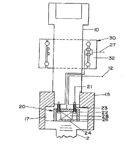
invention, as shown in Fig. 1, is used in conjunction with a bolt 2 and comprises a
. . _ _ _ _ _ _ _ . .
WO 95/22009 PCT/US95/01281 ~
' -4- 2 1 83338
socket 15 h~av!ng ~an i~nterior space 17. The socket 15 engages the bolt 2 for
tensioning the bolt 2 and placing a load thereon. The interior space 17 of the socket
15 is located between the bolt 2 and the socket 15. A socket drive 10 is used inconjunction with the socket 15; and the socket drive 10 is detachably engagable with
5 the socket 15 for changing to different size sockets for a~ullllllu~d~ different sized
bolts 2.
Anr~ u~lld~ lictransducerassembly2oislocatedwithintheinteriorspace
17 of the socket 15 at the bolt 2. The EMAT assembly 20 comprises a housing 22
and a wearplate 24 which contacts the bolt 2. Within the housing 22 and the
10 wearplate 24 is located a pt~lllldllt~lll magnet 28 for producing a magnetic field and
a coil 26 for providing a cunrent. The EMAT assembly 20 is connected to the socket
drive 10 by dl~d~ "~"L bolts 21 and springs 23. A cable 27 is connected to the coil
26 for providing the current to the coil 26. The c-dble 27 is channeled to the coil 26
through a cable routing hole 12 located within the socket drive 10. The cable 27 is
15 connected to the socket drive 10 by a slip ring assembly 30 engaged around the
socket drive 10. The slip ring assembly 30 comprises slip ring brushes 32.
The ele~l,u",a~;"~lic transducer assembly 20 is used as a generator of
ultrasonic waves by locating the coil 26 in a uniform magnetic field produced by the
permanent magnet 28 such that the ultrasonic waves are provided near the surface20 of the metal bolt 2. By l,d"~ur",~, action, a surface current is introduced into the
metal bolt 2. This surface current in the presence of the magnetic field e~ "~s
a Lorentz force which produces oscillating surface stresses. On reception, the surface
of the metal 2 oscillates in the magnetic field thereby inducing a voltage in the coil
26. The transduction process takes place within an el~ u",d~;"~lic skin depth,
25 which for materials such as steel or aluminum, at megahertz frequencies, is a fraction
of a mil.
The present invention provides a very reproducible non-contact system for
generating and detecting ultrasound. Because the current of the EMAT coil 26
directly generates ultrasonic waves in the surface of the bolt 2, the precise time of
30 flight measurements can be made by timing from the current pulse to the first reflection which eliminates many of the problems associated with known,
conventional ultrasonic measuring devices.
Wo 95/22009 PCI/U595/01281
5 - 2 1 8 3 3 3 8
Due - the development of the present invention, some of the prob!ems that
have been ciated with previous efforts to measure bolt loading by ultrasonic
methods have been minimized or eliminated. The EMAT of the present invention
generates and receives ultrasonic waves without the need to contact the material in
S which the waves are traveling. This eli~inates the requirement for a liquid couplant
between the transducer and the material under test, which is the source of significant
error and problems for automating the measurement process.
In operation, the EMAT sensor 20 rotates with the socket 15 and the bolt 2.
Ultrasonic signals are l~d"a",i~ cl and received via the slip rings 32 while testing the
10 bolted joint 2. Alternatively, the trallsducer cable 27 is allowed to twist during the
bolt tightening.
Fig. 2 shows EMAT instrumentation and computer 25 ~ iaillg a display
means 60 and a remote amp and matching network 29 which electrically matches theEMAT coil 26 and cable 27 to the EMAT instrumentation 25. The detector 25, is a
15 computer which takes measurements on the unloaded bolt 2 in order to establish a
base line, and then measures and plots the bolt load while tightening the bolt 2.
As shown in Fig. 1, the EMAT sensor 20 is spring loaded by springs 23 so that
the sensor 20 is automatically seated on the head of a bolt 2 as soon as the socket
15 is placed on the bolt head 2. The E~' ~T sensor 20 is attached to the drive
20 assembly 10 in such a manner so th. -everal different bolt sizes can be
dl_~UllllllOd..'~.d by changing sockets 15. EMAT measurements are taken as follows:
priorto loading, i.e. on an unloaded bolt, continuously during the loading of the bolt,
and after the loading of the bolt. When the desired load has been reached, the
s--~or 20 does not have to be removed. This eliminates the errors previously
25 encountered in known transducers which are caused by having to attach and remove
the ultrasonic transducers for the two tests, i.e. the preload test and the postload test.
The method according to the present invention is well suited for automotive bolttightening for use in production lines and various robotic applications.
It is well known that .u,,,,,,~r.idl ultrasonic bolt load measurement devices
30 have been found to produce highly variable results primarily due to couplant
variability.
Additionally, the l~pedld~ilil~/ of the EMAT method according to the present
invention for measurements spaced over a period of time is much better than that of
_: . , _ _ _ __ . . . . ..
WO 95/22009 , ~ P~
t ~ i -6- 2 1 83338
conventional ultrasonic methods. It may be desirable to measure the load of a bolt
periodically to ensure that it is still within specifications. Because the EMAT 20
operates without couplant, re-application of the sensor 20 to make periodic
measurements produces results with good accuracy if the load is unchanged.
A preliminary study of the novel concept of the present invention of using an
EMAT for measuring bolt loading was first conducted under laboratory conditions.Fig.3showsane~ ,i",~"Idlset-upusedduringthepl~ alystudy. Atensiontest
set-up 40 was used in conjunction with a bolt loading fixture 4 and 6 and a 50,000
pound loading frame ,UIllI.lli~illg a load device 45. A specimen bolt 2 was loaded
in the tension test set-up 40 at 5,ûO0 pound i~ 1"~"L~ and measurements of arrival
time, load cell output, from load cell 47, and bolt temperature were recorded. The
results of the measuring times for the ~Idll~llliLI~l current pulse to first echo are
illustrated in Fig. 4 for two successive load cycles.
The effect on the accurac~ of the readings caused by removing and replacing
the transducer was tested by removing and replacing the transducer on the head of
the unstressed bolt six times. The maximum variation in the time of flight was 4 nS.
or an error corresponding to ab~out 1.5% of the l~..."""~"d~d load value. The
average variation was only 1.2 nS. or less than 0.5% of the applied load. These
results were unexpected since the ~ dl transducer was not very rugged and
20 indicates that the transducer can be easily removed and replaced without introducing
significant errors in bolt preload measurements. The ability to remove and replace
thetransducerwithoutintroducingsignificanterrorsallowsforthereloadingofabolt
in an assembly where preload c2n change.
Whileaspecificc:",l,odi~ ,lloftheinventionhasbeenshownanddescribed
25 in detail to illustrate the application of the principles of the invention, it will be
understood that the invention may be embodied otherwise without departing from
such principles.