Note: Descriptions are shown in the official language in which they were submitted.
WO 96/18933 PCT/US95/15750
2la33sl
FIELD EFFECT TONING METHOD/APPARATUS
BAC~GROUND AND SUMMARY OF THE INVENTION
Commercial non-impact printin~ system~ typically use a
method of developing toner (liquid or dry powder) to an electric or
m~gn~tic latent image created by some writing means. Generally
associated with the creation of the latent image are an im~ging
cylinder, some means for ereating the image, and associated
10 conditioning means for residual im~ge removal and cleaning. All of
these components wear out during system operation and must be
added to the cost of each printed page. Toner itself costs somewhere
(in 1994) in the n~ighhorhood of $0.0006 to $0.001 per page. Adding
in the rest of the consnmable component-~, the cost is raised to a
range of $0.0625 to $0.0065 per page. Latent image non-impact
printing carries a considerable additional im~ing cost. Direct-to-
paper im~ging systems such as ink jet technologies carry only the
cost of the ink; however, many of these technologies do not obt~in
im~ging as desirable or quick or versatile as latent image systems do.
Another technology that is not commercial but attempts to
obtain direct-to-paper im~ging (that is without a latent image) is the
m~gn~tstylus technology, exemplified by U.S. patents 3,816,840,
4,402,000, and 4,464,672. This technology uses a dry, m~ netically
attractable, electronically conductive toner which forms a connecting
25 path from the primary to the secondary electrode. The "write"
condition of the toner is the active electrode condition and extra toner
is removed by a magnetic field. Typically inductive charging of the
toner for the "write" condition is used, and the secondary electrode
uses a dielectric receptor material above it. This technology has not
30 become commercial, however, primarily due to im~ging and
PCT/US95/15750
WO 96/18933
2 21 83351
background removal problems, as well as problem.c with transferring
the toner to a substrate.
Another proposed technology for direct-to-paper im~ging is
called direct electrostatic printing (DEP), and is exemplified by U.S.
5 patents 4,860,036 and 4,810,604. This technology typically utilizes
some sort of a toner conveyor which moves the toner past the
primary electrodes formed by multiple apertures, with an electrically
insulated base member clad on one side thereof with a continuous
conductive layer of metal,-and on the opposite side a segment~d
o conductive layer. Toner passes through the apertures into a web
which is moving past a stationary backing electrode or shoe which
can be connected up to potential sources to either effect printing or
cleaning operations. The toner delivery systems in DEP technology
leaves much to be desired, and the dual conductive apertures spaced
apart from each other by an insulating member are more complex
than is desired.
According to the present invention a method and apparatus are
provided which are able to achieve direct-to-paper im~ginF (that is
without a latent image) in a simple yet effective m~nner. The
20 technology of the present invention may be referred to as "field effect
im~ging". The invention lltili7:es non-conductive, non-m~gn~tic toner
which does not form a connecting path from the primary to secondary
electrodes, has the "write" condition when the primary electrode is
de-energized, removes extra toner with an electric field, does not use
25 inductive charging of the toner for the "write" condition, and uses
simple primary electrodes, typically pin or stylus simple electrodes
disposed in an array. In the field effect method only the electrostatic
adhesion force dominates in control of the toner on a "secondary
electrode" (typically a conductive surface which can be either
30 positively or negatively charged, or grounded, such as a roller with a
WO 96/18933 PCT/US95/lS750
2 1 8335 1
~. 3
conductive surface), and im~ing is subtractive in nature (that is the
toner in the non-image areas is removed by the primary electrodes).
According to one aspect of the present invention, a method of
applying a toner image to a moving substrate (typically paper web),
5 using a non-conductive, non-m~gnetic toner having a 5-20 micron
mean particle size, at least a first moving conductive member, and an
array of primary electrodes, is provided. The method comprises the
steps of substantially consecutively and continuously: (a) Electrically
charging the non-conductive, non-m~gnetic toner having a 5-20
0 micron mean particle size to a level of at least about 8 micro
Coulombs/gram. (b) Bringing the first moving conducting memher
into operative association with the electrically charged toner from
step (a) so that toner particles a&ere thereto, for-ming a layer
thereon. (c) Selectively energizing individual primary electrodes from
5 the array of primary electrodes to cause them to apply electric fields
to the layer of toner particles in a no-write condition to effect removal
of toner particles where the applied electric field exists at a level
greater than an electrostatic adhesion force on the toner particles in
the layer, the applied electric field times the charge on the toner
20 being greater than Q2/(16 * Il * o * r2), where Q is the charge on the
toner, Eo iS the permitivity constant, and r is the toner particle
radius; or selectively de-energizing individual primary electrodes from
the array of primary electrodes to cause them not to apply electric
fields to the layer of toner particles in a write condition, in which the
25 layer of toner particles merely passes past the array of primary
electrodes without toner particles being removed from the layer. (d)
Tr~n~ferring the toner particles rem~ining on the first conductive
member after it passes past the array of primary electrodes to the
moving substrate. And, (e) fusing the toner particles to the
30 substrate.
WO 96/18933 PCT/US95/15750
21 833~ ~
Step (c) is typically practiced to apply an electric field of
greater than about 1.6 volts/1~M when in the no-write condition. Step
(c) is typically further practiced so that the magnitude of the electric
field applied in the no-write condition is equal to (Vl-V2)tD, where V
5 = the electric potential of the primary electrode, V2 = the electric
potential on the first conductive surface, and D = the separation
distance between the primary electrode and the first conductive
surface, D = about 75-250 microns.
Typically the toner-is in an electrostatic fluidized bed during
0 the practice of step (a), such as shown in European published patent
application 494454, and the first surface is moved past the fluidized
bed in the practice of step (b), and the toner removed in the no-write
condition during the practice of step (c) returns to the fluidized bed.
Preferably the primary electrodes are pins or styluses, and the first
5 conductive surface is the exterior surface of the first roller. In that
case step (d) is practiced by bringing the exterior surface of the first
roller into contact with the moving substrate and by applying a
transfer electrical force (e.g. using a transfer corona on the opposite
side of the moving web of paper from the roller) to the toner on the
20 exterior surface of the first roller to cause the toner to transfer from a
first roller to the substrate. Alternatively a second roller may also be
provided having a second conductive exterior surface, in which case
step (d) may be practiced by electrically transferring the toner from
the first roller to the second roller, and then bringin~ the exterior
25 surface of the second roller into contact with the moving substrate,
and by applying a transfer electrical force to the toner on the exterior
surface of the second roller to cause the toner to transfer from the
second roller to the substrate. Step (c) may be practiced by lltili7ing
the primary electrode disposed between the first and second rollers,
30 or associated with the first roller remote from the second roller.
WO 96/18933 PCT/US95/15750
`~ 1 83351
-.. . . ... .
Where two rollers are utilized, premature transfer of toner from the
first roller to the second roller may be provided by shielding the
rollers from each other remote from the area of closest proximity
between them.
Step (c) is typically practiced by electronic switching of the
connection of each primary electrode pin or stylus of the array to a
source of electrical potential, by-controlling electronic switches using
a computer. A flow shield may also be provided mounted just
"downstre~m" of the primaIy electrode array in the direction of
o movement of the first roller to cause the toner particles removed from
the first roller to fall by gravity into the fluidized bed below it.
According to another aspect of the present invention a field
effect im~ging apparatus is provided which comprises the following
elem~nt-s: An electrostatic fluidized bed of non-conductive, non-
m~gnetiC toner particles. Means for mounting a moving substrate on
which toner is to be applied. Me~ns for electrically charging toner
particles in the fluidized bed. A first roller having a conductive outer
surface mounted for rotation adjacent the fluidized bed to receive
charged toner particles from the fluidized bed in a layer on the
20 surface thereof. An array of primary electrodes. Means for
selectively applying electrical potenti~l, or no electrical potential, to
the individual primary electrodes depen(ling upon whether a no-write
or write condition is the exist. And, means for transferring toner
from the first roller to a moving substrate mounted by the means for
25 mounting a moving substrate.
The array preferably comprises an array of pin or stylus
electrodes and the array may either be mounted adjacent but spaced
from the first roller and between the fluidized bed and the substrate
(in which case the toner transferring means transfers toner from the
30 first roller directly to the moving substrate), or a second roller may
WO 96/18933 PCT/US95/15750
21 83351
. . ~ ,.
:
be provided between the first roller and the substrate. In this case
the primary electrodes may either be associated with the first
electrode, or may be disposed between the rollers so that only the
"write" toner is tr~n~ferred from the first roller to the second roller.
The array pins or styluses may be mounted so that they are
spaced about 75-250 microns from the first roller, or from between
the rollers. A flow shield for causing toner removed by the no-write
conditions of the prim~ry electrodes to fall back into the fluidized bed
may be pro~ided as well as a shield between the first and second
o rollers. The means for electrically charging toner particles in the
fluidized bed may be a rotating cylinder with a plurality of corona
points, or a corona wire, immersed in the fluidized bed.
According to another aspect of the present invention a field
effect im~inE apparatus is provided comprising the following
15 elements~ e~nc for mounting a moving substrate. A source of
charged toner particles. A first roller having a conductive outer
surface mounted for rotation adjacent the source to receive charged
toner particles from the source in a layer on the surface thereof. An
array of pin or stylus primary electrodes. Me~n~ for selectively
20 applying electrical potential, or no electrical potential, to the
individual pin or stylus primary electrodes depen(linE upon whether a
no-write or write condition is the exist. And, means for transfernng
toner from the first roller to a moving substrate mounted by the
means for mounting a moving substrate.
The first roller conductive exterior surface may be coated with
or comprise a conductive hard metal coating; for example it may be
coated with hard chrome, tungsten carbide, silicon carbide, or
Diamond-Like Nanocomposite.
It is the primary object of the present invention to provide a
30 simple yet effective direct-to-paper im~ging system and method. The
WO 96/18933 PCT/US95/15750
`` 2 1 833~ ~
"direct writing" field effect toning method and apparatus of the
invention have no latent image to deal with, the rollers utilized are
conductive with hardened sllrf~ces that need no particular
conditionin~, the im~ginF (primary) electrode array con~in~ no
5 wearing parts and is not in contact wit,h any moving sn~ces, and in
general the only consnm~hle is the toner itself. This and other
objects of the invention will become clear from an inspection of the
detailed description of the invention, and from the appended ~ im~.
10BRIEF DESCRIPTION OF THE DRAWINGS
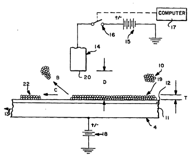
FIGURE L9 is a s~h~m~tic side view showing operation of the
field effect toning apparatus and method acco.di..g to the invention;
5FIGURE lB is a schem~tic top view of the apparatus of
FIGURE 1A;
FIGURE 2 is a gr~hic~l representation illustrating the
percentage of toner released under the influence of a primary
20 electrode acco~di~lg to the invention with increasing applied electric
field;
FIGURE 3 is a side sçh~m~tic view of a preferred embodiment
of e~emrl~ly apparatus according to the present invention;
FIGURE 4 is a side detail view of the prima~ electrode
portion of the apparatus of FIGURE 3;
FIGURE 6 is a view like that of FIGURE 3 for another
30 embodiment of apparatus according to the invention;
WO 96tl8933 PCT/US95/15750
- ~- 21 ~3351
FIGURE 6 is a view like that of FIGURE 3 for still another
emborliment of the apparatus according to the present invention;
FIGURE 7 is a detail side view of the primary electrode and
5 related components of the apparatus of FIGURE 6; and
FIGURE 8 is a view like that of FIGURE 3 for still another
embodiment.
DETATTTi~n DESCRIPTION OF lh~; DRAWINGS
FIGURES lA and lB are designed to illustrate the basic
principles of the field effect toning technology accoldi~g to the
present invention. The basic elem~nts of the apparatus comprise a
5 toner supply (a non-conductive, non-m~netic toner) shown
schematically by reference numeral 10, a moving conductive
substrate 11, which may have a particularly hard conductive coating
12 thereon (e.g. fo~ned of hard chrome, tungsten carbide, silicon
carbide, or Di~m-n-l-Like Nanocomposite) which moves in the
20 direction 13, and an array of primary electrodes 14 of c-~n~n~tive
material which can be electrically biased into the "write/no-write"
condition by ntili~ing voltage source 15 and high speed switching
circuitry 16 which is controlled by a computer 17. Only one electrode
14 is illustrated in FIGURE LA, but the array-like nature of the
25 electrodes is illustrated in FIGURE lB. The electrodes 14 may be in
a single line in the array as shown in solid line in FIGURE lB, or
may be disposed in a two tlimen~ional array, as indicated when the
dotted line electrodes 14' from FIGURE lB are considered. FIGURE
lB only shows two of the electrodes 14 connected up to electronic
WO 96/18933 PCT/US95/15750
2 1 ~335 1
switches 16, but it is to be understood that all will be connected to
the source of electric potential 15 through an electronic switch 16.
The conductive surface 11, which may be considered a
secondary electrode, can be biased to either electrical polarity by a
5 voltage source 18, or held at electrical ground dep~ntling upon the
particular applic~tion The outer surface of the coating 12 is ground
and polished to a surface ron~hne.ss of four micro inches rms or
better.
The toner layer 19 which is .deposited on the surface 11, 12
10 typically has a t~lirknes,s T; norrnally the layer 19 is a bi-layer of
toner with a thickness of about 20 microns. The preferred mean
particle size diameter of the toner is about 10.5 microns, however the
process is workable with toners from about 5-20 microns mean
particle size. The toner in layer 19 is typically charged to a level of
5 at least 8~C/gm (either positive or negative), and more typically to
10uC/gm charged to mass ratio by field charging (Panthenier
charging) lltili~ing a high voltage corona source. That is the voltage
supplied is on the order of about 7 kV.
The primary electrodes 14 can be of any number of cross-
20 sectional shapes, such as the round shapes illustrated in solid line inFIGURE lB, or the flat polygonal (e.g. quadrate) shapes illustrated
at 14' in dotted line in FIGURE lB. The face 20 of each electrode
14 -- which preferably is in the form of a pin or stylus, as illustrated
schematically in FIGURES lA and lB -- is mounted spaced a
25 distance D from the surface 11, 12. The preferred distance D is about
75-250 microns, and during operation no electrical path is created by
the toner between the electrode 14 and the surface/electrode 11, 12.
The electrode 14 is energized in the no-write condition, and
when energized the toner particles within the influence of the field
30 generated by the electrode 14 "jump" off the surface 11, 12 (the
PCT/US95/157~0
WO 96/18933
- ~ ` ? . ~ 2 1 8335 1
..
electric field force on the toner particles having exceeded the
electrostatic a-lhesion force) as indicated at B in FIGURE L~ The
toner im~ge 22, which passes under the array of electrodes 14 when
in the "write" condition, passes on as indicated by the directional
5 arrow C to the transfer position where the image is transferred to the
substrate and fused by convention~l means (e.g. heating). In the "no-
write" condition, a primary electrode 14 is switched to the bias level
provided by voltage source 15. This forms an electric field between
the primarsr and secondary electrodes. The field is of magnitude,
o E = (V~ - V2) /D
where Vl is the potential on the primary electrode 14, V2 is the
potential on the secondary electrode (11, 12) and D is the separation
distance between the electrodes. The toner layer 19 is separated
from the secondary electrode 11/12 under this condition when the
5 electric field force on the toner particles exceeds the electrostatic
arlhesion force, that is
FE ~ Fat
or
Q*E>Q2/(4*II*~O*r2)
20 to a first order approximation. Q is the charge on the toner, Eo iS the
permitivity constant, and r is the toner particle radius. Separated
particles B are removed from the surface by electric fields only and
are recycled to the toner source 10 (e.g. the electrostatic fluidized
bed).
In the "write" condition, the electrode 14 bias 15 is turned off
by computer 17 control of switch 16, allowing the toner image 22 to
pass on and be directed to the transfer position where the image is
transferred to the substrate (not shown in FIGURES lA and lB) and
fused by conventional means.
WO 96/18933 PCT/IJS95/157~0
11 2183351
Since the toner supply 10 will in actuality comprise a large
population of particles which vary in size and therefore overall
amount of charge, not all of the particles will be released from the
surface 11, 12 with the same applied electric field. With the varying
5 charges and equivalent diameters, there is a range in electric field
magnitude over which the particles are released from the surface 11,
12, and FIGURE 2 schem~tically illustrates a typical plot of the
percentage of toner released with increasingly applied electrical field.
Transfer of-toner begins at a low threshold field 23 and continues
o until the entire population is transferred after passing a total
transfer field magnitude 24. In practice, this is not total transfer,
but amounts to about 95%, probably due to some very low charged or
wrong charge toner particles. To assure a total transfer of toner
between the surfaces 14, 11/12 of FIGURES lA and lB, the electric
field should exceed the total transfer magnitude 24 by some nomin~l
amount. In practice the total transfer magnitude is about 1.6
volts/~M. Therefore electric fields greater than this must be utilized,
and in actual practice fields within the range of about 2.2-2.4
volts/11M are utilized.
FIGURES 3 and 4 schematically illustrate a preferred
apparatus ntili~ing the basic field effect toning principle illustrated in
FIGURES 1 and 2. In this embo&ent the source of toner comprises
a fluidized bed 25 of toner particles (e.g. having an about 5-20 micro~
mean particle size), being disposed within the container 26 and
25 having a porous plate 27 through which fluidizing air passes, being
supplied from the air plenum 28. Means are provided for electrically
charging the toner particles in the bed 25. Such means are
illustrated schematically at 29 in FIGURE 3 and comprise a cylinder
30 which rotates within the bed 25 and has corona points (e.g. four
30 equally spaced arrays of points) around the surface thereof.
WO 96/18933 PCT/US95/15750
. 21 ~3351
12
Alternatively such means may co~ ;se a corona wire, or any other
suitable meçh~ni.cm for imparting a charge to the non-conductive,
non-m~gnetic toner particles within the bed 25. The electrical
charging means 29 are connected up to a source of electrical pot~nti~
5 illustrated sçhem~tically at 32 in FIGURE 3.
Disposed above the bed 26 is a first roller 33 having a
conductive surface 34. The roller 33 may be connected up to a source
of electrical potential 35 (either a positive or negative source) or may
be electrica~ly grounded. It is typically mounted for rotation about a
10 hori~ont~l axis and powered by a conventional motor. In operative
association therewith is an array of primary electrodes illustrated
sçh~n~tic~lly at 36 in FIGURE 3. The array 36 corresponds to the
primary electrodes 14, 14' of the array illustrated in FIGURES lA
and lB, while the roller surface 34 corresponds to the surface 11/12
15 in FIGURE lA
The primary electrodes 36 are shown in more detail in
FIGURE 4. Each electrode 36 typically comprises a biased shield
plate 37, an insulating layer 38, and an array of conductive pins or
styluses 39. Ihe pins 39 are connected up to a negative pulse
20 electronic switch 40 controlled a computer 41. There is a gap 42,
with ~im~ncion "d" in FIGURE 4, typically about 75-250 microns,
between the surface 34 and the closest snrf~es of the pins 39.
When the computer 41 energizes a pin 39 through the
electronic switch 40 associated therewith, toner particles, as intlic~t~d
25 sçhem~tically at 43 in FIGURE 4, are caused to "jump" from the
surface 34. This "no-write" condition essentially removes the
"background" areas of the toner on the surface 34 and returns the
toner particles forming them to the fluidized bed 2~, which is just
below the electrodes 36. If desired a flow shield 44 or the like is
30 provided ' downstre~m of the primary electrodes 36 in the direction
WO 96/18933 PCT/US95/15750
2 1 ~ 3 3 5 ~
13
45' of rotation of the roller 33 to help return the removed toner 43 to
the fluidized bed 25.
After the toner on the roller 33 passes past the primary
electrodes 36, there wil~ be only image (or what will become jm~ge)
5 areas 45 on the surface 34. These image toner areas 45 must then be
transferred to a moving substrate 46 (see FIGURE 3), such as a
paper web. The substrate 46 is mounted by rollers, such as the roller
47, or other convention~l equipment for moving a web past and into
contact with a rotating cylinder.
In the embodiment illustrated in FIGURE 3, transfer of the
image areas 45 is ~ccomrlished ntili~ing a second roller or cylinder
48 having a conductive exterior surface 49. The roller 48 is also
typically connected up to a source of electrical potential such as a
source 50 illustrated s~h~m~tic~lly in FIGURE 3. The roller 48 is
mounted for rotation about an axis parallel to the axis of rotation of
the roller 33, and they are so mounted that the transfer point 51
therebetween is a small gap at which the surfaces 49, 34 are in close
proximity.
In order to preclude premature transfer of the toner im~geS 45
20 from the surface 34 to the surface 49 in the weak fields as the toner
images 45 approach the closest proximity area 51, an electrical shield
52 is provided between the images 45 as they move in direction 45'
toward the gap 51.
The cylinder 48 is rotated in a direction 54 that is opposite to
25 the direction 45'. At the transfer area 51 where the rollers 48, 33 are
in closest proximity, the same electrical forces are applied as
indicated earlier, causing the image toner 45 to transfer from the
surface 34 to the surface 49. The roller 48 then rotates clockwise to a
contact point with the paper web 46 where a transfer means -- such
30 as the conventional transfer corona 56 on the opposite side of the
WO 96/18933 PCT/US95/15750
2 1 8 3 3 5 1
~ . ! ~ 14
substrate 46 from the roller 48 -- effects transfer of the toner images
from roller 48 to the web 46. The web 46 then continues to move in
the direction 57 to a conventional fuser 58 (e.g. which applies heat to
the toner), which fuses the toner to the substrate 46.
In order to remove excess toner from the cylinders 33, 48,
convention~l scrapers 59, 60 are provided, the removed toner falling
under the force of gravity into the fluidized bed 25.
FIGURE 6 illustrates another exemplary embo~lim~nt
according to this invention. In FIGURE 5, components comparable to
0 those of the FIGURES 3 and 4 emboflim~nt are shown by the same
reference numeral. This embodiment differs from the embotlim~nt of
FIGURES 3 and 4 only in that the single roller 33 is provided, and
the toner images 45 on the surface 34 thereof are brought directly
into contact with the moving substrate 46 (which moves in the
5 opposite direction of that illustrated in FIGURE 3). Also, in this
particular situation the roller 33 is connected to ground, as indicated
s~hem~tically at 62, rather than to a source of electrical potential.
In the FIGURES 6 and 7 embodiment, components essentially
identical to those in the FIGURES 3 and 4 embo~iment are shown by
20 the same reference numeral, whereas components only comparable
are shown by the same numeral only preceded by a "1n.
In the FIGURES 6 and 7 embodiment, the first roller 133
rotates in the direction 145' opposite the direction 45', and there is no
primary electrode directly associated therewith Rather the primary
26 electrodes, illustrated schematically at 136 in FIGURE 6, and seen
more clearly in FIGURE 7, are mounted between the rollers 133, 148.
When the field is generated to create an image by computer 141
control of the electronic switches 140 associated with each of the pins
or styluses 139, the image 145 is caused to be lifted from the roller
30 133 surface 134 onto the roller 148 surface 149, while the
WO 96/18933 PCT/US95/15750
-
s ~l 83351
kground" toner rem~inC on the surface 134 as illustrated at 64 in
FIGURE 7. An actual electrical field analysis of the configuration of
primary electrodes 136 and rollers 133, 148 illustrated in FIGURES 6
and 7 was done with a finite element analysis package called
5 "ELECTRO". This ~l~mnn~trated that the electrodes 136 can develop
a field of over 2.3 volts/~M at the surface 134, enough to overcome
the electrostatic ~tlhe.sion force on the toner particles on the surface
134. Once the toner images 145 are transferred to the surface 149
they are applied to the web 46 in the same way as described with
0 respect to FIGURE 3 except that the direction 154 is opposite the
direction 54.
FIGURE 8 illustrates another embodiment with components
comparable to those in the FIGURE 3 embofiiment shown by the
same reference nnmeral. In this embo-liment there is no array of pin
5 or stylus electrodes, but rather transfer is provided between the
surfaces 34, 49 at the gap 70 therebetween basically in bulk,
electronic switch 71 being controlled to selectively connect the voltage
source ~0 to the roller 48 to cause transfer, or disconnect it to
preclude tr~n~fer. When transfer is desired, images (typically in the
20 form of lines) are transferred to the surface 49 and they are then
brought into contact with the substrate 46. If desired, the roller 48
could be constrllcted of a plurality of conductive rings (at least on the
surface 49 thereof) separated by insulators, with a different switch 71
associated with each ring.
2~ It will thus be seen that according to the present invention an
advantageous method and apparatus for field effect toning are
provided. The invention allows direct-to-paper im~ging ntili7:ing very
simple components, with no wearing parts, and with the only
consumable being the toner itself. While the invention has been
30 herein shown and described in what is presently conceived to be the
WO 96/18933 PCT/US95/15750
21 83351
16
most practical and preferred embotliment thereof it will be apparent
to those of ordinary skill in the art that many modifications may be
made thereof wi~hin the scope of the invent;on, which scope is to be
accorded the broadest interpretation of the appended claims so as to
5 encomrass all equivalent methods and devices.