Note: Descriptions are shown in the official language in which they were submitted.
21 ~3385
TITLE: A REVERSED PHASE AUDI0 rKEQ~J~;NcY DIVIDING CIRCUIT
This invention relates to a reversed phase audio
frequency dividing circuit.
The use of a speaker can properly amplify a sound
5 source. A speaker generally has a plurality of
resistive-capacitive filters for filtering audio frequency
passing through, therefore unpleasant and noisy audio
f requency can be removed . In order to improve sound
quality, several audio response units are installed for
10 responding different audio frequency. When several audio
response units are installed, suitable filter means must
be used to remove unqualified audio frequency from passing
through the respective audio response units. Figure lA
shows a regular audio filter designed for removing low
15 frequency, in which a plurality of capacitors C1, C2, C3
are respectively connected in series to the audio input
terminal IN, and a plurality of resistors R1 are
respectively connected in parallel to each capacitor.
Figure 2 shows the response curves of the audio frequency
20 before and after passing through the filters, in which the
21 ~33~5
response curve Aa is the original audio frequency response
curve; the response curve Bb is the audio f requency
response curve obtained from that filtered through Cl;
the response curve Cc is the audio frequency response
S curve obtained f rom that f iltered through Cl and C2; the
response curve Dd is that audio frequency response curve
obtained f rom that f iltered through Cl, C2, and C3 .
Figure lB shows a regular audio filter designed for
removing high frequency, in which a plurality of inductors
10 Ll, L2, L3 are respectively connected in series to the
audio input terminal IN, and a plurality of capacitors Cl,
C2, C3 are respectively connected in parallel to each
inductor. From Figure 2, we can see that the gain of
output power is greatly reduced when the sound source is
15 f iltered through several f ilters . Because the gain of
output power will be greatly reduced if the sound source
is f iltered through several f ilters, the original power of
the sound source must be relatively increased so that the
output power of the speaker can be increased. However,
20 because there is a limitation on the output power of
21 B33~5
regular audio equipment, it is difficult to compensate the
loss of gain due to the operation of f ilters .
This invention is directed to a reversed phase audio
frequency dividing circuit.
S According to the present invention, undesired high
and low audio frequency is eliminated when positive phase
audio freguency offsets negative phase audio frequency,
therefore the sound guality of each sound discrimination
speaker is improved.
Other objects of the invention will in part be
obvious and in part hereinaf ter pointed out .
The invention accordingly consists of features of
constructions and method, combination of elements,
arrangement of parts and steps of the method which will be
exemplified in the constructions and method hereinafter
disclosed, the scope of the application of which will be
indicated in the claims following.
FIG. lA is a circuit diagram of a low frequency
f ilter circuit according to the prior art;
FIG. lB is a circuit diagram of a high frequency
21 ~33~5
filter circuit according to the prior art;
FIG. 2 is the response curves of the audio frequency
before and after passing through the filters of the low
frequency f ilter circuit of FIG. lA;
FIG. 3A is a circuit diagram of a low-pass f ilter
according to the present invention;
FIG. 3B is an alternate form of the low-pass filter
of FIG. 3A;
FIG. 4 is an audio frequency response curve obtained
from the low-pass filter of FIG. 3i
FIG. 5A is a circuit diagram of an intermediate-pass
filter according to the present invention;
FIG. 5B shows an alternate form of the
intermediate-pass f ilter of FIG. 5A; and
FIG. 6 is an audio frequency response curve obtained
from the intermediate-pass f ilter of FIG. 5 .
For purpose to promoting an understanding of the
principles Qf the invention, reference will now be made to
the embodiment illustrated in the drawings. Specific
20 language will be used to describe same. It will,
21 833~5
s
nevertheless, be understood that no limitation of the
scope of the invention is thereby intended, such
alternations and further modif ications in the illustrated
device, and such further applications of the principles of
5 the invention as illustrated herein being contemplated as
would normally occur to one skilled in the art to which
the invention relates.
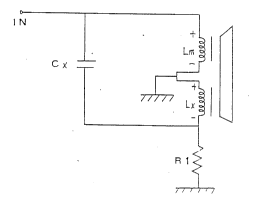
Ref erring to FIG . 3A and 4, sound source input
terminal is connected to the master sound coil Lm of the
10 speaker by a main circuit. A sub-circuit is connected in
parallel to the main circuit. The sub-circuit comprises a
high-pass capacitor Cx at the front end, which permits
limited intermediate and high frequency to pass, and an
auxiliary sound coil Lx of reversed phase relative to the
15 master sound coil Lm at the rear end. The output terminal
of the auxiliary sound coil Lx and the output terminal of
the master sound coil Lm are connected in series to
grounding terminal. Because the auxiliary sound coil Lx
provides an intermediate/high frequency sound signal of
ZO reversed phase, it offsets int~ te/high frequency
21 83385
sound waves fro~ the main circuit. Therefore, the area
defined by B, C, and D in FIG. 4 offsets the relative
upper triangular area above A and C, and the audio
frequency wavelength curve can extend to D. This
S arrangement completely eliminates high frequency sound
effect. This low-pass filter further comprises a variable
resistor Rl for regulating the volume of the output signal
of the sub-circuit . The low-pass f ilter can be arranged
in another form as shown in FIG. 3B.
Referring to FIG. 5A and 6, the design of the
intermediate-pass filter is similar to that of the
aforesaid low-pass filter. The main circuit is connected
between the sound source input terminal IN and the master
sound coil LM. A capacitor Cl is installed in the main
15 circuit of the intermediate-pass f ilter to remove low
frequency from inputted sound source. A high-pass
capacitor Cx is connected in parallel to the input end of
the main circuit for letting high frequency pass. An
auxiliary sound coil Lx of reversed phase and a variable
20 resistor Rl are connected in series to the master sound
21 83385
coil LM. Therefore, high frequency and low sound
frequency are removed from the sound source when the sound
source passes through the intermediate pass f ilter, and
only the intermediate frequency sound are is left (see
5 Figure 6 ) . Furthermore, the intermediate-pass f ilter can
be arranged in another form as shown in Figure 5B.
Referring to FIGS. 4 and 6 again, the design of the
reversed phase audio frequency dividing circuit causes
little loss of the gain. Therefore, sound effect output
10 can be greatly increased, and sound quality can be greatly
improved. Because the f ilter uses only an auxiliary sound
coil of reversed phase to match with different capacitors
C1, Cx, the structure is simple, and the installation is
easy .
The invention is naturally not limited in any sense
to the particular features specified in the forgoing or to
the details of the particular embodiment which has been
chosen in order to illustrate the invention.
Consideration can be given to all kinds of variants of the
20 particular embodiment which has been described by way of
21 833~5
example and of its constituent elements without thereby
departing from the scope of the invention. This invention
accordingly includes all the means constituting technical
equivalents of the means described as well as their
S combinations.