Note: Descriptions are shown in the official language in which they were submitted.
CA 02183639 2000-07-07
METHOD FOR SUChING/DI:TERMINING LIQUID AND PIPETTING DEVICE
DRIVEN AIVD COI\fTROLLED ACCORDING TO METHOD
TECHNICAL FIELD
The present invention relates to an entirely new method for
sucking/determining the
level of a liquid and to a pipetting; device driven and controlled according
to the method.
and more particularly to a method for sucking/detertnining the level of a
liquid in which
driving required for upward/downward movement of a nozzle for sucking a liquid
such as a
sample for a blood serum and a reagent as well as for pipetting a liquid to
cylinders each for
sucking and discharging ~:he liquid is accurately controlled, so that a liquid
level and a
sucking rate of a liquid by the nozzle, and contamination of foreign matters
therein such as
bubbles or fibrins or the like in the liquid can accurately be detected, as
well as to a
pipetting device driven an<i controllled according to the method.
BACKGROUND ART
Generally, important matters .required for enhancing pipetting precision are
to detect a
level of a blood serum sample and a reagent or similar liquid, to measure a
pipetting rate
thereof, to measure an absolute Sucking rate thereof, to adhere the liquid to
the outside of
the nozzle, and to detect contamination thereof by foreign matters such as
bubbles and
fibrins.
For this reason, conventionally, a method has been employed, in which an
electrode is
immersed in the liquid together with the nozzle and the liquid level is
detected according to
a conductive state with the; electrode so that an inserting rate (distance) of
the nozzle to the
liquid is controlled, but in the case of this method, the electrode must be
immersed into the
liquid, so that the electrode must be washed after each measurement thereof to
prevent
cross contamination, and as a result, there have been such problems us that a
device
CA 02183639 2000-07-07
Doc. No 76-4 CA PCT Patent
becomes complicated, and that size and cost of the device increase.
Then, recently a method of detecting a liquid level using a pressure sensor
was
proposed. In this method, a sucking pressure of the nozzle when a vapor is
sucked is
different from that when a liquid is sucked, so that the liquid level is
detected by detecting
the difference between the pressure's, whereby an inserting rate (distance) of
the nozzle to
the liquid is controlled, and for this reason only the nozzle is contacted
with the liquid, and
the method has such advantages as that a cleaning function is not required,
which makes it
possible to simplify the device as well as to reduce the costs.
However, the method of detecting a liquid level using a pressure sensor has
several
problems such as that the resolution is low and the sensitivity is not high,
and also that the
method is easily affected by an atmospheric pressure as well as by pressure
change due to
the sucked air, and also affected by vibrations generated due to
upward/downward
movement of the nozzle a~; well as by a noise of the pipetting device itself
or a change of a
voltage, and for this reason malfunction thereof occurs quite often, and the
reliability
thereof as a measuring means is quite low.
An optical liquid level detecting means is far more effective as a means to
solve the
problems as described above. Various means in which both an optical fiber for
irradiating
light therethrough and an optical fiber for receiving light are disposed
outside the nozzle.
have been proposed for the liquid level detecting methods based on the
conventional
technology.
However, in the liquid level detecting means using light for detecting a
liquid level
based on the conventional technology, in which both a fiber for irradiating
light
therethrough and an optical fiber for receiving light are provided outside the
nozzle for
catching reflected light from a liquid level with the optical fiber for
receiving light to detect
the level thereby. These fibers are inserted in parallel to each other
together with the nozzle
into a vessel for a liquid. For this reason it cannot be denied that the
method has a
CA 02183639 2000-07-07
Doc. No 76-4 CA PCT Patent
possibility of cross contamination caused by the fiber contacting with the
liquid adhered to
the wall surface of the vessel for a liquid. Moreover, the amount of light
caught by the
optical fiber for receiving light is extremely small, which makes it difficult
to accurately
detect a liquid level. In addition the extremely minute control is required,
which is difficult
because there also occur some cases where a timing for receiving the reflected
light is
shifted or light cannot be received by the fact that the liquid level becomes
slightly wavy
due to vibrations of the device.
The present invention was made to solve the problems as described above, and
it is an
object of the present invention to provide an entirely new method of
sucking/determining
the level of a liquid, including, for instance, detection of a liquid level in
which a light
receiving body is provided. in a nozzle, and fluctuation of light in a
disposable tip such as a
pipetting tip or in an opening section at the lower end of a tip of a cleaning
system are
detected thereby from the ;side of the nozzle under circumstances similar to
seeing the other
opening section from one end of a tunnel, so that it is possible to extremely
sensitively
detect a liquid level, contamination by foreign matters therein, or an
interface between
liquids each having a different color without being affected by the wavy
liquid level, as
well as to provide a pipetting device driven and controlled according to the
method.
Namely, a basic principle of the present invention is characterized in that
the various types
of detecting operation are carried out by catching a moment as if a light
instantly changed
shows fluctuation in a flash when a substance near to (or sucked into) a space
cut off from
the outside of the environment is changed, for instance, from vapor to liquid.
SUMMARY OF THE INVENTION
Accordingly, the present invention provides a method for suckina/determinin~
the
level of a liquid contained in a vessel by means of a nozzle, comprising the
steps of:
CA 02183639 2000-07-07
Doc. No 76-4 CA PCT P~ncnt
positioning a light receiver inside the nozzle; and
receiving a light irradiation proceeding from the liquid at or near an opening
located
at a lower end of a dispos;zble tip or a tip of a cleaning system attached to
the lower end of
said nozzle through a space defined by the said disposable tip or the tip of
the cleaning
system and entering into the lower end of said nozzle, and detecting
fluctuation of said
received light irradiation.
Accordingly, the prf~sent invention provides a method for sucking/determinin~
the
level of a liquid contained in a vessel by means of a nozzle, comprising the
steps of:
providing a light receiver; and
receiving light irradiation proceeding from the liquid at or near an opening
located at
a lower end of a disposable tip or a tip of a cleaning system attached to the
lower end of
said nozzle through a space defined by the said disposable tip or the tip of
the cleaning
system and entering into the lower end of said nozzle, and detecting
fluctuation of said
received light irradiation, wherein the light receiver is not positioned
exteriorly of the
disposable tip or on an outer side of the nozzle.
Accordingly, the prc;sent invention provides a pipette device, in which the
driving
force required for pipettinL; a liquid. to a cylinder, for changing the
relative position between
said cylinder and said nozzle upward/downward, and for sucking/discharginl a
liquid is
controlled, comprising:
a nozzle having an opening section located at a lower end thereof;
a disposable tip or a tip of a cleaning system having a first, upper end
attached to the
lower end of said nozzle a:nd having a second, lower end adapted to suck
liduid thereinto:
a light receiver positioned inside the nozzle for receiving light proceeding
from the
liquid at or near the opening of said lower end of said disposable tip or said
tip of a
a
CA 02183639 2000-07-07
Doc. No 76-4 CA PCT Patent
cleaning system and entering into the opening section of said nozzle; and
a light detector for detecting fluctuations of said received light.
To achieve the obje<;t as described above, in the method of
sucking/determining the
level of a liquid according to the present invention, it is essential to
detect variations of
lights caused by a liquid accommodated in the vessel with the nozzle for
sucking the liquid.
In the present invention, a disposable tip or a tip of a cleaning system is
attached to a
lower edge section of a nozzle, and the nozzle detects a liquid level by
receiving tluctuation
of light close to the disposable tip or to an opening section at a lower end
of the tip in the
cleaning system, for instance, light reflected from the liquid surface.
Furthermore, in the present invention, not only the liquid level is detected,
but also a
liquid is filled in the disposable tip or the tip of a cleaning system
detachably attached to
the nozzle, light is passed through the liquid in the disposable tip or the
tip of a cleaning
system, and a change in light amount of the sucked liquid is detected, so
that, for instance, a
suction rate of the liquid, v~ransparency thereof, contamination by bubbles
therein, clogging
and a state wherein water has been exhausted are determined.
And furthermore, in the present invention, fluctuation of light wavelength can
be
detected and a change of color is checked by the nozzle, whereby a liduid
level can also be
detected. The color change can be c:letected through the liquid according to
the nozzle, to
detect a color of the colored vessel accommodating a liquid therein.
Alternatively, the color
change can be detected through the liquid according to the nozzle, to detect a
color of a
rack or a color of a holder, in which a transparent vessel accommodating a
liquid therein is
vertically provided. It is needless to say that detection of color change
herein includes
detecting an interface on which layers are separated by identifying a color of
a blood clot or
a blood coagulant in a process, fc>r instance, in which the nozzle is movin~~
downward while
sucking a blood serum.
CA 02183639 2000-07-07
Doc. No 76-4 CA PCT Patent
In the present invention, the light is not limited to a case of light which is
directly
received from the disposar~le tip or from the opening section at the lower end
of the tip of a
cleaning system attached to the nozzle, and, for instance, light may be
irradiated or received
through a transparent disposable tip or a tip of a cleaning system.
In the present invention, it is desirable that the nozzle itself is formed
with a light
transmitting material in a tubular :form, or only the lower edge section
thereof is formed
with the light transparent material, or a bundle of optical fibers are
provided therein.
In this case, it is desirable that a lens body is provided in the tip section
of a
disposable tip or a tip of a cleaning system in the nozzle, for instance, in a
slightly lower
side than the opening section in the lower end of the disposable tip or the
lower edge
thereof, so that the lens can be focused at a position where fluctuation of an
amount of
received light can be checked with high precision. The lens may be used
depending on the
form or length of the tip, diameter of the opening section, light-proof
property or the like.
and in this case, the lens may be provided in any of a light irradiating
section and/or a light
receiving section, and a concave lens may be used as well as a convex lens, or
a plurality of
concave and convex lenses may be combined to be used.
In the present invention, light is supplied to a liquid accommodated in a
vessel
through the nozzle itself or through a fiber for light irradiation and a light
receiving fiber
each provided inside the nozzle, or is supplied from the outside of the
nozzle.
A supply of light from the outside of the nozzle includes irradiation of IiQht
from the
outside of a transparent vessel for containing a liquid to said liquid, or
irradiation of light to
a liquid through a disposable tip or a tip of a cleaning system in addition to
irradiation of
light from an optical fiber provided near the outside of the nozzle to the
liquid. It is
needless to say that, irradiation of light is not limited to a case where
light is irradiated
continuously, but light may be irradiated in a pulsed mode.
6
CA 02183639 2000-07-07
Doc. No 76-4 CA PCT Patent
Data obtained by the method for sucking/determining the level of a liquid
having the
construction as described above is preferably used as data for controlling a
pipetting device
in which driving required for pipetaing a liquid to cylinders for moving
upwarcl/downward
the nozzle as well as for sucking/discharging a liquid is controlled.
BRIEF DESCRIPTION O:F DRAWINGS
Fig. 1 is an explanatory view showing schematic configuration of a pipetting
device
according to a first embod~.ment of the present invention;
Fig. 2 is an explanatory view showing schematic configuration of a pipetting
device
according to a second embodiment of the present invention;
Fig. 3 is an explanatory view showing schematic configuration of a pipetting
device
according to a third emboa.iment of the present invention;
Fig. 4 is a cross-sectional view showing a state in which a lens body is
provided in the
light irradiating body and a light receiving body in the pipetting device
according to a
fourth embodiment of the ~~resent invention;
Fig. 5 is an explanatory view showing schematic configuration of a pipetting
device
according to a fifth embodiment of the present invention:
Fig. 6 is an explanatory view showing a schematic configuration of a
pipettin;~ device
according to a sixth embodiment of the present invention;
Fig. 7 is an explanatory view showing schematic configuration of a pipetting
device
according to a seventh embodiment of the present invention;
Fig. 8 is an explanatory transverse sectional view showing a level (a surface
area) of a
7
CA 02183639 2000-07-07
Doc. No 76-4 CA PCT Patent
liquid to be sucked in a case where it is detected whether a sucked amount of
liduid is
sufficient or not with the pipetting device according to an eighth embodiment
of the present
tnventton;
Fig. 9 is an explanatory transverse sectional view showing a state of the
surface of a
sucked liquid when contamination of a liquid by foreign matters contained
therein is
detected with the pipetting device according to a ninth embodiment of the
present
invention;
Fig. 10 is an explanatory view showing a transmission path for light when a
cleaning
tip of the pipetting device according to a tenth embodiment of the present
invention is
empty; and
Fig. 11 is an explanatory view showing a transmission path for light when the
inside
of the cleaning tip of the pipetting device is filled with a cleaning liquid.
BEST MODE FOR CARF;YING C>UT INVENTION
Detailed description is made for embodiments of the present invention with
reference
to the related drawings.
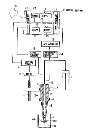
Fig. 1 shows a schematic configuration of a pipetting device to which the
method for
sucking/determining the lt~vel of a liquid according to the first embodiment
of the present
invention is applied, arid the pipetting device basically comprises a nozzle 2
in
communication with and connected to a cylinder 1; an arm 3 for holding the
nozzle 2; a
drive mechanism 4 for moving the arm 3 upward and downward; a motor 5 for
operatin~T
the drive mechanism 4; a, driving circuit 6 for controlling regular/reverse
rotation of the
motor 5; and a disposable tip 8 detachably attached to the lower edge section
7 of the
nozzle 2.
8
CA 02183639 2000-07-07
Doc. No 76-4 CA PCT f'atcnt
The nozzle 2 is moved downward at a specified position by the drive mechanism,
the
liquid level WL is detected by a liquid level detecting mechanism described
later, then a
liquid 10 such as a serum or a reagent accommodated in a vessel 9 is sucked,
and then the
pipetting device moves upward to discharge the sucked liduid to another vessel
(not shown
herein). It should be noce:d that each of the basic configurations of the
pipetting devices
according to the present invention is the same as that which is well known so
lon;~ as a
particular mention is nor made in the present specification, so that detailed
description
thereof is omitted herein.
In the nozzle 2, a bore hole 2a through which a liquid is passed along the
longitudinal
direction in the center section of the nozzle 2 constructed the same as for a
nozzle based on
the conventional technology is formed, the upper edge section of the bore hole
?a is in
communication with and connected to the cylinder 1, and at the same time in
the nozzle 2.
the liquid level detecting mechanism comprising a light irradiating body I 1
having yn
optical fiber or a bundle of more than two optical fibers and a light
receiving body 12 is
incorporated, and the lower edge sections of the light irradiating body I 1
and of the light
receiving body 12 are arranged each in its exposed state in the bottom surface
of the lower
edge section 7 in the nozzle 2 formed in a concave shape.
Connected to the upper edge section of the light irradiating body 1 1 is a
light emitting
section 13 for emitting and supplying light. The light emitting section 13
supplies light to
the light irradiating body 11, the light irradiated from the. lower edge
section of the light
irradiating body 11 is reflected on the liquid surface WL and is received by
the light
receiving body 12, then the received and reflected light is converted to a
voltage by a
photoelectric converting section l~ connected to the upper edge section of the
light
receiving body 12, a signal for the converted voltage value is sent to an A/D
converter 1 ~
for converting it to a digit;zl signal, the digital signal from the A/D
converter 1 > is received
by the control section 16 (e.g. microcomputer) for executing various types of
controlling.
and the data for a control signal outputted from the control section 16 is
displayed on a
CA 02183639 2000-07-07
Doc. No 76-4 CA PCT Pacnt
display means 21 comprising a CRT or the like.
The control section l6 comprises an input interface 17 for receiving a digital
data
signal from the A/D converter 15; a ROM 18 for storing therein a program
required for
computing an outputted signal; a CPU 19 for executing a specified computing
according to
a program stored in the ROM 18; a RAM 20 for temporarily storing therein a
result of
computing or data; an output interface 22 for outputting a control signal to
various objects
to be controlled or to the display me°ans 21 in the device; and a timer
23. It should be noted
that the CPU 19 previously stores therein, for instance, specified values or
predetermined
values identifying a reflected state of light, executes computing and
determining such as
comparing the specified values or the predetermined values to measured values,
anti
transmits an instruction for driving; and controlling each of the mechanisms
aceordin~ to
the determination.
Intrusion of light from outside or leakage of light transmitted through light
irradiating
body 11 and light receiving body 12 can be prevented without fail by cutting
off light with
light-proof film Layers in which the peripheral surface of the nozzle 2 and an
internal
peripheral surface of the bore hole 2a, or a peripheral surface of the light
irradiatinU body
11 and the light receiving body 12 are subjected to black coloring or the like
or to
mirroring, respectively, so that a clear light signal without any noise can be
transmitted.
which makes it possible to control more smoothly the control section. It is
needless to say
that each of the lower edge sections of the light irradiating body 1 1 and
light receiving body
12 is formed, for instance, to a concave lens form, and also formed to a form
in which the
transmitted light is focused to near the opening at the lower end section of
the disposable
tip 8, and the light reflected on the liquid surface enters into the nozzle 2
for being detected.
Next, a description is made. for operations of detecting a liquid level in the
pipetting
device constructed as described above.
CA 02183639 2000-07-07
Doc. No 76-4 CA PCT Patent
When liquid level dt°tection is fed to the control section l6. the
control section 16
outputs a control signal to the light emitting section 13, and the light
emitting section 13
supplies light to the light irradiating body 1 1. A supply of the light is
executed continuously
or executed by blinking it at certain time intervals. Then, simultaneously
when the light is
supplied, the control section 16 also outputs a control signal to the driving
circuit 6, and the
driving circuit 6 moves the arm 3 downward into the vessel 9 containing a
liquid by means
of motor 5. Further, the c~~ntrol section 16 starts moving the arm downward
and the tuner
23 incorporated therein starts counting.
In association with the downward movement of the arm 3, the light irradiated
from
the light irradiating body :l I into a disposable tip 8 is, as shown in Fig. l
, irradiated from
the opening section 8a at the lowt~r end thereof onto a liquid surface WL, and
the light
reflected on the liquid surface WL, reenters from the opening section 8a at
the lower end
into the disposable tip 8 and is received by the light receiving body 12.
Namely, the light outputted from the opening section 8a at the lower end of
the
disposable tip 8 through the light irradiating body 11 and irradiated to the
liquid surface
WL, when the opening section 8a at the lower end thereof is above the liquid
surface, is
reflected on the liquid surface WL, or passes under the liduid surface, so
that the light
hardly returns to the opening 8a at the lower end thereof, and for this
reason, the amount of
light received by the light receiving body 12 is at a low level.
The amount of light received by the light receiving body 12 while the
disposable tip 8
is moving downward to a certain position does not change much.
Then, when the disposable tip 8 has moved downward to a certain position. and
light
exiting from the opening ,section 8~a at the lower end thereof through the
light irradiating
body 11 and irradiated to the liquid surface WL is reflected on the liquid
surface WL and
again received into the disposable tip 8 from the opening section 8a at the
lower end
thereof, the amount of light in the disposable tip 8 cut off from the outside
environment
CA 02183639 2000-07-07
Doc. No 76-4 CA PCT Patent
momentarily reaches a high level, so that the light amount at that moment is
detected, and
the detected amount thereof is compared to a specified value or identified as
a
predetermined value. In this case, reflected light can be caught at more
accurate timing if
the cylinder 1 is moved downward 'while sucking an air.
The photoelectric converting section 14 successively converts the change of
the light
amount during the time described above to a voltage value, and the control
section 16
compares the voltage value to the specified value or identifies that as a
predetermined
value, and immediately terminates the downward movement of the arm 3 and/or
the
sucking operation by the cylinder 1.
The signal for voltage value obtained as described above is converted to a
digital
signal with the A/D converter 15, and the fluctuations of a series of voltages
can be stored
in the control section 16.
The control section 16 measures with the timer 23 a period of time required
from start
of measurement until a point of time when the maximum voltage value is
obtained, and
computes a liquid level W:L corresponding to a time previously stored therein
with the CPU
19. The data as to whether the liquid level WL has been detected or not is
displayed on the
display means 21 comprising a CR.T or the like. In the embodiment, however,
description
was made for a case where: a liquid level was detected by using the timer 23
as an example.
but the present invention is not limited to the case described above. and it
is possible to
detect a liquid level (po~~ition for driving) by using, for instance, a well
known pulse
counter or an encoder.
When the liquid level is detected as described above, the control section l6
provides
an instruction to the driving circuit 6 to move the arm 3 downward. and the
arm 3 descends
for the distance instructed by the control section 16 according to the
instruction. so that the
tip section of the disposable tip r3 i~, inserted into the liquid 10, and a
required amount of the
liquid 10 in the vessel 9 f~~r a liquid is sucked into the disposable tip 8
with the cylinder 1
l2
CA 02183639 2000-07-07
Doc. No 76-4 CA PCT Patent
sucking the liquid according to an instruction by the control section 16.
In the pipetting device according to the embodiment, as described above, a
momentary specified value; or a momentary predetermined value, when
fluctuation of the
amount of received light reflected on the liquid surface in a space section
formed by the
disposable tip 8 is extremely different, can be caught as a noiseless clear
signal without
being affected by the outside. Thus, a liquid level can be detected with high
precision, and
the nozzle 2 itself is not contacted with the inside surface of the vessel 9
containing a
liquid, which makes it possible to prevent cross contamination without fail.
It should be noted that, in the first embodiment, description was made for a
case
where the lower edge section of the light irradiating body 1 1 is exposed at
the lower edge
section of the nozzle 2 as an example, but, as described in the second
embodiment shown
in Fig. 2, the same effect: can be obtained even if the lower edge section of
the light
irradiating body 11 is led to the outside of the nozzle 2, and light is
irradiated from the
outside of the nozzle 2, is reflected on the liquid surface WL, and the light
reelected thereon
is received by the light receiving body 12 provided in the lower edge section
of the nozzle 2
through the opening section 8a at the lower end thereof.
Fig. 3 shows the third embodiment according to the present invention, and in
this
embodiment, the device can also be constructed so that the lower edge sections
of the light
irradiating body 11 and th~° light receiving body 12 are provided in
the side section of the
lower edge section 7 of the nozzle 2 in the exposed state respectively, and
the disposable
tip 8 may be formed with a transparent and photoconductive material, and in
that case IiQht
irradiated from the light irradiating body I1 passes through the disposable
tip 8 and is
irradiated to the liquid surFaee WL through the opening section 8a at the
lower end of the
disposable tip 8, the reflected light again passes through the disposable tip
8. and the
amount of the light can be detected with the light receiving body 12.
Fig. 4 shows the fourth embodiment according to the present invention, and in
this
t3
CA 02183639 2000-07-07
Doc. No 76-4 CA PCT !'atent
embodiment, focusing lenses 24A, 24B are provided each at a positions lower
than each of
the lower edge sections of the light irradiating body 11 and the light
receiving body 12, the
light irradiated from the light irradiating body I1 is focused at a point F,
on the liquid
surface WL, so that a brighter reflected light can be received, and the
resolution can further
be improved.
The focusing lenses 24A, 24B may be concave lenses or convex lenses, or may be
a
combination thereof, and also the irradiated light may be focused not only on
the point F,
on the liquid surface, but also at a center portion F, of the opening section
8a at the lower
end of the disposable tip ~~, or at a position F; slightly above the opening
section 8a at the
lower end of the disposable tip 8 or at any other appropriate position so long
as a change in
a quantity of received light can be accurately detected. The focusing lenses
24A, 24B may
be provided in either one of the light irradiating body 1 1 or the light
receiving body 12, but
in the present embodiment, a lens is always provided in the side of the light
receiving body
12. However, in the present invention, the focusing lens described above may
not always
be provided therein, and it is quite possible to detect how high the liquid
level WL is even
if light irradiated from the light irradiating body 1 1 is supplied to the
liquid surface without
focusing the light thereon.
On the external and internal peripheral surfaces of the tip 8 shown in Fig. 4.
light-
proof film layers 25, 2E~ each subjected to black colorii~a or mirroring are
formed
respectively. By forming the light--proof film layer, ?5, ?6 each on the
external peripheral
surface as well as on the internal peripheral surface of the disposable tip 8,
intrusion of
light from the outside into the tip and leakage of light transmitted
therethrou~h can be
prevented without fail, so that a clear light signal without any noise can be
received with
the light receiving body 12, and control can be more smoothly provided.
Fig. 5 shows a configuration of a nozzle section in a pipetting device
according to a
fifth embodiment of the present invention, and the embodiment shows a case
where the
W
CA 02183639 2000-07-07
Doc. No 76-4 CA PCT Patent
light receiving body 12 is located at the center of the nozzle 2, and is
surrounded with a
ring-shaped light irradiating body R 1 , with a small gap between the two.
This annularly-
shaped gap formed between the light irradiating body 1 1 and light receiving
body 12 is in
communication with and connected to the cylinder 1 via a suction conduit K.
The other
configuration features and effects thereof besides those described above are
the same as
those in the first embodiment, so the same reference numerals used in the
first embodiment
are assigned to the portions corresponding thereto in the figure and detailed
description
thereof is omitted herein.
Fig. 6 shows a pipetting device according to a sixth embodiment of the present
invention, and the embodiment shows a case where the invention is applied to a
device for
pipetting, for instance, a reagent or other liquid accommodated in a bottle
30, in which the
light receiving body 12 is provided at the center of the nozzle 2, the light
irradiatinyT body
11 formed in a ring shape is proviided outside the light receiving body 12,
and a suction
conduit K for sucking the liquid in the bottle 30 is provided outside the
light irradiating
body 11. The other configuration features and effects thereof besides those
described above
are the same as those in the first embodiment, the same reference numerals
used in the first
embodiment are assigned to the portions corresponding thereto in the figure
and detailed
description thereof is omitted herein.
Fig. 7 shows a seven~:h embodiment of the present invention. In this
embodiment, the
same configuration in the nozzle side is tormed as that in the second
embodiment shown in
Fig. 2. Light is irradiated from the outside of a colored or transparent
vessel 9 containing a
liquid, or from the outside of a rack 27 in which the vessel 9 is vertically
provided. An
amount of light or changt~ of color (light wavelength) is detected through the
liquid 10
contained in the vessel 9. It should be noted that detection uccordin~ to
color as described
above can also be executed in the configuration of the first embodiment.
As described above, as in a case where a light amount is detected, the
position of a
t;
CA 02183639 2000-07-07
Doc. No 76-4 CA PCT F'utcnt
liquid level WL can be detected evt°n if a change of light wavelength
(color) is detected by
the light receiving body 12.
By constructing the device so that color can be detected as described above,
in a case
where two colors of liquid in the vessel 9, for instance, a blood serum and a
blood clot or a
blood serum, a blood coagulant, and a blood clot are separated into layers by
centrifugation
and accommodated therein, an interface between a blood serum and other
substances can
be detected according to a change of the color thereof by slowly moving down
the
disposable tip 8, which makes it possible to prevent contamination of the tip
due to a blood
coagulant or a blood clot ei~fectively and without fail.
Fig. 8 shows an eighth embodiment of the present invention. and in this
embodiment.
determination can easily bc: made as to whether a sucked amount of a liquid is
sufficient or
not by detecting a reflected area o~f the liquid 10 or a difference of the
reflection height
sucked into the disposable. tip 8 according to increase/decrease of the light
amount.
Fig. 9 shows a ninth ~°mbodiment of the present invention, and in this
embodiment, in
a case where a liquid (blood serum) sucked into a disposable tip 8 is
contaminated with
foreign matters B such as hobbles or fibrins, a light amount received by the
light receiving
body 12 varies due to the foreign matters B as compared to that in the normal
case, so that
successive fluctuations of the light amount due to contamination thereof with
the foreign
matters B can easily be detected to determine whether or not the liquid is
contaminated
with the foreign matters B.
Fig. 10 and Fig. 11 show a. tenth embodiment of the present invention. and the
embodiment shows a case where an engaging section 3? of the tip 31 of a
cleaning system
having a concave ring shape is formed at the lower edge section of the nozzle
?. the lower
edge sections of the light irradiating body 1 I and light receiving body l'_'
are each exposed
to the inside of the engaging section 32, and light irradiated from the light
irradiating body
11 can pass through the engaging section 32 of the nozzle ? and be received by
the light
16
CA 02183639 2000-07-07
Doc. No 76-4 CA PCT Patent
receiving body 12 through the tip 31 of a cleaning system formed with a
transparent
material. The other configuration features and effects thereof besides those
described above
are substantially the same as those in the first embodiment, so that the same
reference
numerals used in the first embodiment are assigned to the portions
corresponding thereto in
the figure, and detailed des~~ription thereof is omitted herein.
When the tip 31 of a cleaning system is detachably attached to the nozzle 2 as
described above, and in a case where the inside of the tip 31 is "empty" as
shown in Fi~,. lU.
light irradiated from the lil;ht irradiating body 1 1 passes through the tip
3l to the openinyl
section of the tip 31 of a cleaninL; system, again passes through the tip 3l
to the light
receiving body 12, and is r~°ceived thereat, so that determination can
be made as to whether
the tip 31 is empty (exhausted state) or not by previously measuring an amount
of received
light in this step.
When the inside of the tip 31 is in a state of being filled with a cleaning
liduid as
shown in Fig. 11, light irradiated from the light irradiating body 11 passes
through the
cleaning liquid from the tip 31, again passes through the tip 31, and is
received by the light
receiving body 12, so that ~3etermination can be made as to whether the tip 31
is filled with
a cleaning liquid or not by previous:Ly measuring an amount of received light
in this step.
However, in the embodiments shown in Fig. 10 and Fig. 1 1, the outer surface
of the
tip 31 of a cleaning system should preferably be subjected to the same light-
proof
processing, because thereby the detecting conditions are not affected from
outside of the tip
31, so that the detection the>reof with higher precision can be executed.
As described above, in the present invention. assuming a cane where
sucking/determining a liquid level are executed by using light, a nozzle is
used as a light
receiving body, which makes it possible to detect the level of the liquid
sucked by the;
nozzle, without being affe~~ted by any measuring conditions outside the nozzle
tip. and in
addition the light receiving body is provided in the nozzle, which makes it
possible to
~7
CA 02183639 2000-07-07
Doc. No 76-4 CA PCT Patent
prevent without fail generation of cross contamination caused by contacting
the light
receiving body with a liquid.
In the present invention, not only the liquid level is detected, but also a
liquid is tilled
in a disposable tip or the tip of a cleaning system detachably attached to the
nozzle. Light
is passed through the liquid in the disposable tip or the tip of a cleaning
system, anti
fluctuation of light amount reflected from the sucked liquid is detected, so
that, for
instance, a sucked amount of the liquid, transparency thereof, contamination
by bubbles
therein, clogging, and a stage when water has been exhausted are determined.
Furthermore, in the present invention, fluctuation of light wavelength can be
detected
and a change of color is chf:cked by the nozzle, whereby a liquid level can
also be detected.
In the present invention, according to the nozzle a color change can be
detected
through the liquid to detecC the color of the colored vessel accommodating a
liduid therein.
Alternatively, according to the nozzle, the color change can be detected
through the liquid
to detect a color of a rack or .a color of a holder, in which a transparent
vessel
accommodating a liquid therein is vertically provided, which makes it possible
to detect a
liquid level corresponding t:o a change of color environment outside of the
disposable tip.
With the present invention, .a color of a blood clot or a blood coagulant can
be
identified in a process in which the nozzle is moving downward while sucking a
blood
serum, so that an interface ~~n which layers are separated can easily be
detected.
In the present inveni:ion, the invention is not limited to the case wherein
light is
directly received from the disposable tip or from the opening section of the
lower end of the
tip of a cleaning system attached to the nozzle. For example, light may be
irradiated or
received through a transparent disposable tip or a tip of a cleaning system.
In this case, an external surface and/or an internal surface of the disposable
tip or the
tip of a cleaning system except a portion for transmitting light is coated
with a black film or
U
CA 02183639 2000-07-07
Doc. No 76-4 CA PCT Patent
a mirror film, or the tip is subjected to a light-proof processing such as
coloring, whereby
fluctuations of the light can be detecaed with high sensitivity and accuracy.
In the present invention, the nozzle itself is formed with a light
transmitting material
in a tubular form, and a light irradiating section and a light receiving
section are formed in
the nozzle formed with the light transparent material, or only the lower edge
section thereof
is formed with the light transparent material, or optical fibers are provided
therein, so that a
liquid level can be detected with high precision without any restriction of
liquid sucking
operations by the nozzle.
With the present invention, the light receiving edge section of the optical
fibers is
provided in the bottom surface or the side section of the nozzle, so that
reflected light
entering into the disposable tip can be captured without fail. It is needless
to say that the
nozzle is desirably subjected to a light-proof processing.
In the present invention, light supplied from the light irradiating body is
not
necessarily focused. However, depending on conditions such as a form or a
length of a tip,
a diameter of an opening section, a:nd a light-proof property or the like, a
lens body can be
disposed at the lower end of a disposable tip or a tip of a cleaning system
such that it
focuses light at a point where the change of the amount of received light can
be checked
with high precision. For instance said point could be located at an internal
opening section
at the lower end of a disposable tip or at a position slightly lower than a
lower edge of the
disposable tip. In this case, a liquid level can be detected with high
precision without any
noise therein.
In the present invention, light is supplied to a liquid contained in a vessel
by
transmitting it continuously through a nozzle or blinking it in a flashes
therethrough or by
means of optical filters, or is supplied from the outside of the nozzle.
Data obtained by the method for sucking/determinin; the level of a liquid
having the
~9
CA 02183639 2000-07-07
Doc. No 76-4 CA PCT f'atcnt
construction as described above are used as data for controlling a pipetting
device in which
driving required for pipetting a liquid to cylinders for moving the nozzle
upward/downward
as well as for sucking/discharginl; the level of a liquid is controlled, which
makes it
possible to realize a high precision control.
INDUSTRIAL APPLICAFtILITY
As described above, the method for slICklIlg/detel'Illlnlng the level of a
liduid
according to the present invention amd a pipetting device driven and
controlled according to
the method are applicable for use in procedures such as qualifying,
quantifying, separating.
and pipetting a specimen or a sample, identifying a liquid level, and checking
whether
contents of pipetting are satisfied or not in a clinical inspection. In
addition, it is applicable
to procedures such as qualifying, quantifying, separating, anti pipetting a
used drug.
identifying a liquid level, and checking whether contents of pipetting are
satisfied or not in
a chemical analysis, to procedures such as qualifying, quantifying,
separating, and pipetting
a specimen or a sample, identifying a liquid level, and checking whether
contents of
pipetting are satisfied or not in a DNA analysis, to procedures such tls
qualifying.
quantifying, separating, and pipetting a used drug, identifying a liquid
level, and checkin'=
whether contents of pipetting are satisfied or not in a system of producing
drugs. to
procedures such as qualifying, quantifying, separating, and pipetting a
specimen or a
sample, identifying a liquid level, and checking whether contents of pipetting
are satisfied
or not in a bacteria and virus inspection, to procedures such as qualifying,
quantifyin~l.
separating, and pipetting a specimc°n or a sample. identifying a liquid
level, and checking
whether contents of pipetting are satisfied or not in a water quality
inspection, and
furthermore to procedures such as qualifying, quantifying. separating. and
pipetting a used
drug, identifying a liquid level, and checking whether contents of pipetting
are satisfied or
not each in color synthesis.