Language selection

Search

Patent 2183700 Summary

Third-party information liability

Some of the information on this Web page has been provided by external sources. The Government of Canada is not responsible for the accuracy, reliability or currency of the information supplied by external sources. Users wishing to rely upon this information should consult directly with the source of the information. Content provided by external sources is not subject to official languages, privacy and accessibility requirements.

Claims and Abstract availability

Any discrepancies in the text and image of the Claims and Abstract are due to differing posting times. Text of the Claims and Abstract are posted:

  • At the time the application is open to public inspection;
  • At the time of issue of the patent (grant).
(12) Patent Application: (11) CA 2183700
(54) English Title: MEASURING DEVICE FOR REFINERS
(54) French Title: DISPOSITIF DE MESURE POUR RAFFINEURS
Status: Deemed Abandoned and Beyond the Period of Reinstatement - Pending Response to Notice of Disregarded Communication
Bibliographic Data
(51) International Patent Classification (IPC):
  • B23Q 17/09 (2006.01)
  • D21D 01/00 (2006.01)
  • D21D 01/30 (2006.01)
(72) Inventors :
  • JOHANSSON, OLA (Sweden)
  • KJELLQVIST, OLOF (Sweden)
(73) Owners :
  • SUNDS DEFIBRATOR INDUSTRIES AB
(71) Applicants :
  • SUNDS DEFIBRATOR INDUSTRIES AB (Sweden)
(74) Agent: SMART & BIGGAR LP
(74) Associate agent:
(45) Issued:
(22) Filed Date: 1996-08-20
(41) Open to Public Inspection: 1997-02-22
Availability of licence: N/A
Dedicated to the Public: N/A
(25) Language of filing: English

Patent Cooperation Treaty (PCT): No

(30) Application Priority Data:
Application No. Country/Territory Date
9502892-4 (Sweden) 1995-08-21

Abstracts

English Abstract


The present invention relates to a measuring device for refiners
having refining discs (1, 2) that define between them refining gaps (3)
for refining material on bars (5, 6) arranged between the disc (1, 2), said
bars extending across the refining zones (4) of the refining discs. At
least one bar is in the form of a sensor bar (6) designed to sense the load
(9) exerted on the sensor bar (6) at a number of measuring points along
the bar (6) during refining.


Claims

Note: Claims are shown in the official language in which they were submitted.

CLAIMS
1. A measuring device for refiners having refining discs (1, 2)
that define between them refining gaps (3) for refining material on bars
(5, 6) arranged between the discs (1, 2), said bars extending across the
refining zones (4) of the refining discs, c h a r a c t e r i z e d i n t h a t
at least one bar is in the form of a sensor bar (6) designed to sense the
load (9) exerted on the sensor bar (6) at a number of measuring points
along the bar (6) during refining.
2. A measuring device as claimed in claim 1,
c h a r a c t e r i z e d i n t h a t at least one strain gauge (7) is arranged
at each of the measuring points, to measure the deformation the sensor
bar (6) is subjected to at each point, thus enabling calculation of stresses
exerted on the bar (6).
3. A measuring device as claimed in claim 2,
c h a r a c t e r i z e d i n t h a t strain gauges (7) are arranged at each
measuring point so that the strain there can be divided into load
components acting in separate directions.
4. A measuring device as claimed in claim 3,
c h a r a c t e r i z e d i n t h a t a temperature gauge is also arranged ateach measuring point to enable compensation of the strain
measurement for thermal expansion.
5. A measuring device as claimed in claim 4,
c h a r a c t e r i z e d i n t h a t the temperature gauges are also
utilised to determine the pressure and velocity of steam supplied, as a
function of the radius of the refining disc (1, 2).
6. A measuring device as claimed in any of claims 1-5,
c h a r a c t e r i z e d by a control device connected to the sensor bar
(6) and programmed for conversion of the measured stresses to applied
load and for control of the operating parameters of the refiner, such as
breadth, material viscosity, pressure difference and through-flow.

Description

Note: Descriptions are shown in the official language in which they were submitted.


37~
A l..P~ , device for refiners
The present invention relates to a measuring device for
refiners having refining discs that define between them refining gaps
for refining material on bars arranged between the discs, said bars
extending across the refining zones of the refining discs.
In known technology the energy applied is measured in the
main motor. Thus only the total energy applied is measured. The
object of the present invention is instead to measure the actual energy
applied on the material to be refined, as a function of the radius of the
refining disc. Using this information as a basis, the refiner can then be
controlled for optimal pulp quality and minimal energy ~:ol.~u-.l~,lion.
If the energy applied to the inlet zone of the refiner is too high, for
instance, fibre damage may occur and the outer refining zone will not
operate under optimal conditions. Similarly, if insufficient energy is
supplied to the inlet zone, the other zones will be unable to deal with
the through-flow required. The operating parameters that can be
varied are gap breadth, viscosity of the material to be refined, pressure
difference and through-flow, to mention but a few.
The present invention has a particular application area in
refiners having several independent refining gaps. In a refiner con-
sisting of a rotor having refiner segments on both sides and two stators,
one for each side of the rotor, only the total load is obtained since the
rotor is common to both refining zones. Similarly, the conically
shaped peripheral zone in a conical refiner can be adjusted
independently of the inner, flat zone. Hitherto it has not been
practically possible to discover how much energy is applied to one zone
compared with another. Thanks to the invention, refiners having one
or more refining zones can be controlled more accurately since it is
then known where the load has been applied.
Admittedly it is known through SE-B 7 601 019-8 to measure
e.g. temperature or pressure on the material in the refining gap by
placing sensors there. However, the load between bars and material is
still not accessible.

2 2 1 ~370~
The above-mentioned objective is fulfilled by the measuring
device according to the invention in that it exhibits the characteristics
defined in the claims.
The invention will now be described in more detail with
S reference to the ac.u~.lJallyillg drawings in which
Figure 1 shows a radial section through the inner part of two
refining discs in a refiner and
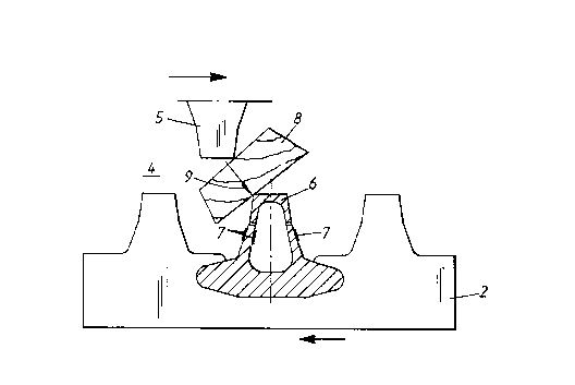
Figure 2 shows a view perpendicular to the bars of the
refining discs with one sensor bar in cross section.
Figure 1 shows a typical refining zone in cross section. The
two refining discs 1 and 2 move with a certain constant speed of
rotation in relation to each other. The material to be refined is fed into
the refining gap at the centre of the refining discs, in Figure 1 from
below, and enters the refining zone 4. There the bars 5 and 6 in the
15 refining machinery will be subjected to a load from the material. This
load is dependent on the properties of the material, the breadth of the
refining gap, through-flow, temperature, moisture content and
geometry of the machinery. The energy level applied is dependent on
many variables. It is well known, for instance, that at temperatures
20 above the glass transition temperature, the energy required to break
down the wood into smaller particles is much less than at temperatures
somewhat below the glass transition l~ allu~. The significance of
the moisture content for the energy applied is also well known,
although its mechanism is not quite clear. In general, refining pulp
25 with a lower moisture content (high viscosity) gives higher specific
energy. Similarly the refining gaps and through-flow levels greatly
influence the specific energy applied.
The parameters mentioned above, with the exception of the
geometry of the machinery, can be used to control the load applied,
30 thus producing a control system with feedback.
To this end at least one of the bars has, according to the
invention, been made in the form of a sensor bar 6. This sensor bar is
provided along its length with strain gauges 7 distributed over a
number of measuring points along the bar 6. Figure 2 shows three
35 strain gauges 7 at one measuring point. Measuring the strain at two or

3 21 83700
more points on the surface of the sensor bar enables determination of
the deformation.
Figure 2 shows a piece of wood 8 in the material to be refined,
being subjected to mechanical processing between the bars 5 and 6. This
5 operation may take several forms. The piece of wood may, for instance,
be ~ ul~Lt ~ed, crushed or fibrillated in the refining zone. In the figure,
the piece 8 is crushed between the bar 5 and the sensor bar 6 when the
bars move in relation to each other as indicated by the horizontal
arrows. When the sensor bar 6 is loaded as indicated by the arrow 9 it
10 will be slightly deformed. This deformation will be measured by the
strain gauges 7, so located that the strain can be divided into load
components acting in separate directions.
The stresses to which the sensor bar 6 is subjected can then be
related to the strain with the aid of linear equations, provided that the
15 liquid limit of the material has not been reached. This conversion is
performed in a control device, where a computer program calculates
the load applied as a function of the strain measured. The solution can
be obtained analytically or numerically depending on the geometry of
the sensor bar. The energy applied as a function of the radius of the
20 refining disc is stated in kilowatt per millimetre, for instance.
Suitably, the ~ .allu~ is also measured at each mrAcllring
point, in order to enable ~ .p~l~salion of the strain measurement for
thermal expansion. The temperature gauges can also be used to
determine the pressure and velocity of steam supplied, as a function of
25 the radius of the refining disc.

Representative Drawing
A single figure which represents the drawing illustrating the invention.
Administrative Status

2024-08-01:As part of the Next Generation Patents (NGP) transition, the Canadian Patents Database (CPD) now contains a more detailed Event History, which replicates the Event Log of our new back-office solution.

Please note that "Inactive:" events refers to events no longer in use in our new back-office solution.

For a clearer understanding of the status of the application/patent presented on this page, the site Disclaimer , as well as the definitions for Patent , Event History , Maintenance Fee  and Payment History  should be consulted.

Event History

Description Date
Inactive: IPC expired 2020-01-01
Inactive: IPC from MCD 2006-03-12
Time Limit for Reversal Expired 2000-08-21
Application Not Reinstated by Deadline 2000-08-21
Deemed Abandoned - Failure to Respond to Maintenance Fee Notice 1999-08-20
Application Published (Open to Public Inspection) 1997-02-22

Abandonment History

Abandonment Date Reason Reinstatement Date
1999-08-20

Maintenance Fee

The last payment was received on 1998-08-06

Note : If the full payment has not been received on or before the date indicated, a further fee may be required which may be one of the following

  • the reinstatement fee;
  • the late payment fee; or
  • additional fee to reverse deemed expiry.

Patent fees are adjusted on the 1st of January every year. The amounts above are the current amounts if received by December 31 of the current year.
Please refer to the CIPO Patent Fees web page to see all current fee amounts.

Fee History

Fee Type Anniversary Year Due Date Paid Date
MF (application, 2nd anniv.) - standard 02 1998-08-20 1998-08-06
Owners on Record

Note: Records showing the ownership history in alphabetical order.

Current Owners on Record
SUNDS DEFIBRATOR INDUSTRIES AB
Past Owners on Record
OLA JOHANSSON
OLOF KJELLQVIST
Past Owners that do not appear in the "Owners on Record" listing will appear in other documentation within the application.
Documents

To view selected files, please enter reCAPTCHA code :


To view images, click a link in the Document Description column. To download the documents, select one or more checkboxes in the first column and then click the "Download Selected in PDF format (Zip Archive)" or the "Download Selected as Single PDF" button.

List of published and non-published patent-specific documents on the CPD .

If you have any difficulty accessing content, you can call the Client Service Centre at 1-866-997-1936 or send them an e-mail at CIPO Client Service Centre.


Document
Description 
Date
(yyyy-mm-dd) 
Number of pages   Size of Image (KB) 
Abstract 1996-12-01 1 12
Description 1996-12-01 3 143
Claims 1996-12-01 1 44
Drawings 1996-12-01 1 20
Representative drawing 1997-07-23 1 6
Reminder of maintenance fee due 1998-04-20 1 111
Courtesy - Abandonment Letter (Maintenance Fee) 1999-09-19 1 187
Fees 1998-08-05 1 44