Sélection de la langue

Search

Sommaire du brevet 2183700 

Énoncé de désistement de responsabilité concernant l'information provenant de tiers

Une partie des informations de ce site Web a été fournie par des sources externes. Le gouvernement du Canada n'assume aucune responsabilité concernant la précision, l'actualité ou la fiabilité des informations fournies par les sources externes. Les utilisateurs qui désirent employer cette information devraient consulter directement la source des informations. Le contenu fourni par les sources externes n'est pas assujetti aux exigences sur les langues officielles, la protection des renseignements personnels et l'accessibilité.

Disponibilité de l'Abrégé et des Revendications

L'apparition de différences dans le texte et l'image des Revendications et de l'Abrégé dépend du moment auquel le document est publié. Les textes des Revendications et de l'Abrégé sont affichés :

  • lorsque la demande peut être examinée par le public;
  • lorsque le brevet est émis (délivrance).
(12) Demande de brevet: (11) CA 2183700
(54) Titre français: DISPOSITIF DE MESURE POUR RAFFINEURS
(54) Titre anglais: MEASURING DEVICE FOR REFINERS
Statut: Réputée abandonnée et au-delà du délai pour le rétablissement - en attente de la réponse à l’avis de communication rejetée
Données bibliographiques
(51) Classification internationale des brevets (CIB):
  • B23Q 17/09 (2006.01)
  • D21D 01/00 (2006.01)
  • D21D 01/30 (2006.01)
(72) Inventeurs :
  • JOHANSSON, OLA (Suède)
  • KJELLQVIST, OLOF (Suède)
(73) Titulaires :
  • SUNDS DEFIBRATOR INDUSTRIES AB
(71) Demandeurs :
  • SUNDS DEFIBRATOR INDUSTRIES AB (Suède)
(74) Agent: SMART & BIGGAR LP
(74) Co-agent:
(45) Délivré:
(22) Date de dépôt: 1996-08-20
(41) Mise à la disponibilité du public: 1997-02-22
Licence disponible: S.O.
Cédé au domaine public: S.O.
(25) Langue des documents déposés: Anglais

Traité de coopération en matière de brevets (PCT): Non

(30) Données de priorité de la demande:
Numéro de la demande Pays / territoire Date
9502892-4 (Suède) 1995-08-21

Abrégés

Abrégé anglais


The present invention relates to a measuring device for refiners
having refining discs (1, 2) that define between them refining gaps (3)
for refining material on bars (5, 6) arranged between the disc (1, 2), said
bars extending across the refining zones (4) of the refining discs. At
least one bar is in the form of a sensor bar (6) designed to sense the load
(9) exerted on the sensor bar (6) at a number of measuring points along
the bar (6) during refining.

Revendications

Note : Les revendications sont présentées dans la langue officielle dans laquelle elles ont été soumises.


CLAIMS
1. A measuring device for refiners having refining discs (1, 2)
that define between them refining gaps (3) for refining material on bars
(5, 6) arranged between the discs (1, 2), said bars extending across the
refining zones (4) of the refining discs, c h a r a c t e r i z e d i n t h a t
at least one bar is in the form of a sensor bar (6) designed to sense the
load (9) exerted on the sensor bar (6) at a number of measuring points
along the bar (6) during refining.
2. A measuring device as claimed in claim 1,
c h a r a c t e r i z e d i n t h a t at least one strain gauge (7) is arranged
at each of the measuring points, to measure the deformation the sensor
bar (6) is subjected to at each point, thus enabling calculation of stresses
exerted on the bar (6).
3. A measuring device as claimed in claim 2,
c h a r a c t e r i z e d i n t h a t strain gauges (7) are arranged at each
measuring point so that the strain there can be divided into load
components acting in separate directions.
4. A measuring device as claimed in claim 3,
c h a r a c t e r i z e d i n t h a t a temperature gauge is also arranged ateach measuring point to enable compensation of the strain
measurement for thermal expansion.
5. A measuring device as claimed in claim 4,
c h a r a c t e r i z e d i n t h a t the temperature gauges are also
utilised to determine the pressure and velocity of steam supplied, as a
function of the radius of the refining disc (1, 2).
6. A measuring device as claimed in any of claims 1-5,
c h a r a c t e r i z e d by a control device connected to the sensor bar
(6) and programmed for conversion of the measured stresses to applied
load and for control of the operating parameters of the refiner, such as
breadth, material viscosity, pressure difference and through-flow.

Description

Note : Les descriptions sont présentées dans la langue officielle dans laquelle elles ont été soumises.

37~
A l..P~ , device for refiners
The present invention relates to a measuring device for
refiners having refining discs that define between them refining gaps
for refining material on bars arranged between the discs, said bars
extending across the refining zones of the refining discs.
In known technology the energy applied is measured in the
main motor. Thus only the total energy applied is measured. The
object of the present invention is instead to measure the actual energy
applied on the material to be refined, as a function of the radius of the
refining disc. Using this information as a basis, the refiner can then be
controlled for optimal pulp quality and minimal energy ~:ol.~u-.l~,lion.
If the energy applied to the inlet zone of the refiner is too high, for
instance, fibre damage may occur and the outer refining zone will not
operate under optimal conditions. Similarly, if insufficient energy is
supplied to the inlet zone, the other zones will be unable to deal with
the through-flow required. The operating parameters that can be
varied are gap breadth, viscosity of the material to be refined, pressure
difference and through-flow, to mention but a few.
The present invention has a particular application area in
refiners having several independent refining gaps. In a refiner con-
sisting of a rotor having refiner segments on both sides and two stators,
one for each side of the rotor, only the total load is obtained since the
rotor is common to both refining zones. Similarly, the conically
shaped peripheral zone in a conical refiner can be adjusted
independently of the inner, flat zone. Hitherto it has not been
practically possible to discover how much energy is applied to one zone
compared with another. Thanks to the invention, refiners having one
or more refining zones can be controlled more accurately since it is
then known where the load has been applied.
Admittedly it is known through SE-B 7 601 019-8 to measure
e.g. temperature or pressure on the material in the refining gap by
placing sensors there. However, the load between bars and material is
still not accessible.

2 2 1 ~370~
The above-mentioned objective is fulfilled by the measuring
device according to the invention in that it exhibits the characteristics
defined in the claims.
The invention will now be described in more detail with
S reference to the ac.u~.lJallyillg drawings in which
Figure 1 shows a radial section through the inner part of two
refining discs in a refiner and
Figure 2 shows a view perpendicular to the bars of the
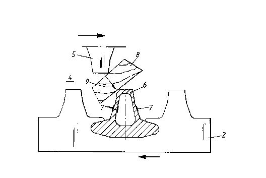
refining discs with one sensor bar in cross section.
Figure 1 shows a typical refining zone in cross section. The
two refining discs 1 and 2 move with a certain constant speed of
rotation in relation to each other. The material to be refined is fed into
the refining gap at the centre of the refining discs, in Figure 1 from
below, and enters the refining zone 4. There the bars 5 and 6 in the
15 refining machinery will be subjected to a load from the material. This
load is dependent on the properties of the material, the breadth of the
refining gap, through-flow, temperature, moisture content and
geometry of the machinery. The energy level applied is dependent on
many variables. It is well known, for instance, that at temperatures
20 above the glass transition temperature, the energy required to break
down the wood into smaller particles is much less than at temperatures
somewhat below the glass transition l~ allu~. The significance of
the moisture content for the energy applied is also well known,
although its mechanism is not quite clear. In general, refining pulp
25 with a lower moisture content (high viscosity) gives higher specific
energy. Similarly the refining gaps and through-flow levels greatly
influence the specific energy applied.
The parameters mentioned above, with the exception of the
geometry of the machinery, can be used to control the load applied,
30 thus producing a control system with feedback.
To this end at least one of the bars has, according to the
invention, been made in the form of a sensor bar 6. This sensor bar is
provided along its length with strain gauges 7 distributed over a
number of measuring points along the bar 6. Figure 2 shows three
35 strain gauges 7 at one measuring point. Measuring the strain at two or

3 21 83700
more points on the surface of the sensor bar enables determination of
the deformation.
Figure 2 shows a piece of wood 8 in the material to be refined,
being subjected to mechanical processing between the bars 5 and 6. This
5 operation may take several forms. The piece of wood may, for instance,
be ~ ul~Lt ~ed, crushed or fibrillated in the refining zone. In the figure,
the piece 8 is crushed between the bar 5 and the sensor bar 6 when the
bars move in relation to each other as indicated by the horizontal
arrows. When the sensor bar 6 is loaded as indicated by the arrow 9 it
10 will be slightly deformed. This deformation will be measured by the
strain gauges 7, so located that the strain can be divided into load
components acting in separate directions.
The stresses to which the sensor bar 6 is subjected can then be
related to the strain with the aid of linear equations, provided that the
15 liquid limit of the material has not been reached. This conversion is
performed in a control device, where a computer program calculates
the load applied as a function of the strain measured. The solution can
be obtained analytically or numerically depending on the geometry of
the sensor bar. The energy applied as a function of the radius of the
20 refining disc is stated in kilowatt per millimetre, for instance.
Suitably, the ~ .allu~ is also measured at each mrAcllring
point, in order to enable ~ .p~l~salion of the strain measurement for
thermal expansion. The temperature gauges can also be used to
determine the pressure and velocity of steam supplied, as a function of
25 the radius of the refining disc.

Dessin représentatif
Une figure unique qui représente un dessin illustrant l'invention.
États administratifs

2024-08-01 : Dans le cadre de la transition vers les Brevets de nouvelle génération (BNG), la base de données sur les brevets canadiens (BDBC) contient désormais un Historique d'événement plus détaillé, qui reproduit le Journal des événements de notre nouvelle solution interne.

Veuillez noter que les événements débutant par « Inactive : » se réfèrent à des événements qui ne sont plus utilisés dans notre nouvelle solution interne.

Pour une meilleure compréhension de l'état de la demande ou brevet qui figure sur cette page, la rubrique Mise en garde , et les descriptions de Brevet , Historique d'événement , Taxes périodiques et Historique des paiements devraient être consultées.

Historique d'événement

Description Date
Inactive : CIB expirée 2020-01-01
Inactive : CIB de MCD 2006-03-12
Le délai pour l'annulation est expiré 2000-08-21
Demande non rétablie avant l'échéance 2000-08-21
Réputée abandonnée - omission de répondre à un avis sur les taxes pour le maintien en état 1999-08-20
Demande publiée (accessible au public) 1997-02-22

Historique d'abandonnement

Date d'abandonnement Raison Date de rétablissement
1999-08-20

Taxes périodiques

Le dernier paiement a été reçu le 1998-08-06

Avis : Si le paiement en totalité n'a pas été reçu au plus tard à la date indiquée, une taxe supplémentaire peut être imposée, soit une des taxes suivantes :

  • taxe de rétablissement ;
  • taxe pour paiement en souffrance ; ou
  • taxe additionnelle pour le renversement d'une péremption réputée.

Les taxes sur les brevets sont ajustées au 1er janvier de chaque année. Les montants ci-dessus sont les montants actuels s'ils sont reçus au plus tard le 31 décembre de l'année en cours.
Veuillez vous référer à la page web des taxes sur les brevets de l'OPIC pour voir tous les montants actuels des taxes.

Historique des taxes

Type de taxes Anniversaire Échéance Date payée
TM (demande, 2e anniv.) - générale 02 1998-08-20 1998-08-06
Titulaires au dossier

Les titulaires actuels et antérieures au dossier sont affichés en ordre alphabétique.

Titulaires actuels au dossier
SUNDS DEFIBRATOR INDUSTRIES AB
Titulaires antérieures au dossier
OLA JOHANSSON
OLOF KJELLQVIST
Les propriétaires antérieurs qui ne figurent pas dans la liste des « Propriétaires au dossier » apparaîtront dans d'autres documents au dossier.
Documents

Pour visionner les fichiers sélectionnés, entrer le code reCAPTCHA :


Pour visualiser une image, cliquer sur un lien dans la colonne description du document. Pour télécharger l'image (les images), cliquer l'une ou plusieurs cases à cocher dans la première colonne et ensuite cliquer sur le bouton "Télécharger sélection en format PDF (archive Zip)" ou le bouton "Télécharger sélection (en un fichier PDF fusionné)".

Liste des documents de brevet publiés et non publiés sur la BDBC .

Si vous avez des difficultés à accéder au contenu, veuillez communiquer avec le Centre de services à la clientèle au 1-866-997-1936, ou envoyer un courriel au Centre de service à la clientèle de l'OPIC.


Description du
Document 
Date
(aaaa-mm-jj) 
Nombre de pages   Taille de l'image (Ko) 
Abrégé 1996-12-01 1 12
Description 1996-12-01 3 143
Revendications 1996-12-01 1 44
Dessins 1996-12-01 1 20
Dessin représentatif 1997-07-23 1 6
Rappel de taxe de maintien due 1998-04-20 1 111
Courtoisie - Lettre d'abandon (taxe de maintien en état) 1999-09-19 1 187
Taxes 1998-08-05 1 44