Language selection

Search

Patent 2183823 Summary

Third-party information liability

Some of the information on this Web page has been provided by external sources. The Government of Canada is not responsible for the accuracy, reliability or currency of the information supplied by external sources. Users wishing to rely upon this information should consult directly with the source of the information. Content provided by external sources is not subject to official languages, privacy and accessibility requirements.

Claims and Abstract availability

Any discrepancies in the text and image of the Claims and Abstract are due to differing posting times. Text of the Claims and Abstract are posted:

  • At the time the application is open to public inspection;
  • At the time of issue of the patent (grant).
(12) Patent Application: (11) CA 2183823
(54) English Title: STRUCTURE OF SAFETY HYPODERMIC SYRINGE
(54) French Title: SERINGUE HYPODERMIQUE AVEC DISPOSITIF DE SECURITE
Status: Deemed Abandoned and Beyond the Period of Reinstatement - Pending Response to Notice of Disregarded Communication
Bibliographic Data
(51) International Patent Classification (IPC):
  • A61M 05/32 (2006.01)
  • A61M 05/50 (2006.01)
(72) Inventors :
  • CHEN, LONG-HSIUNG (Taiwan, Province of China)
(73) Owners :
  • LONG-HSIUNG CHEN
(71) Applicants :
  • LONG-HSIUNG CHEN (Taiwan, Province of China)
(74) Agent: SMART & BIGGAR LP
(74) Associate agent:
(45) Issued:
(22) Filed Date: 1996-08-21
(41) Open to Public Inspection: 1998-02-22
Availability of licence: N/A
Dedicated to the Public: N/A
(25) Language of filing: English

Patent Cooperation Treaty (PCT): No

(30) Application Priority Data: None

Abstracts

English Abstract


A safety hypodermic syringe in which the
needle holder has an arrowhead-like rear retaining hole;
the rubber stopper has an arrowhead-like retainer rod
that can be forced into engagement with the retaining
hole of the needle holder for permitting the needle
holder with the needle cannula to be pulled backwards to
the inside of the barrel by the plunger; the plunger can
be disconnected from the rubber stopper and then
inserted into the front end of the barrel to deform the
needle cannula when the needle cannula is received on
the inside of the barrel.


Claims

Note: Claims are shown in the official language in which they were submitted.

THE EMBODIMENTS OF THE INVENTION IN WHICH AN EXCLUSIVE
PROPERTY OR PRIVILEGE IS CLAIMED ARE DEFINED AS FOLLOWS:
1. A safety hypodermic syringe comprising a
barrel having a front neck and an inside flange inside
said front neck, a needle holder inserted into said
front neck of said barrel and retained in place by said
inside flange of said front neck of said barrel, a
needle cannula fastened to said needle holder, a plunger
moved in said barrel, a rubber stopper connected to said
plunger by a connecting member, wherein said inside
flange of said front neck of said barrel has a front
sloping wall of small slope and a rear sloping wall of
different angles for permitting said needle holder to be
pulled backwards to an inside of said barrel and for
stopping said needle holder from being forced forwards
out of said front neck of said barrel; said needle
holder comprises a longitudinal center through hole,
which imparts a passage between said needle cannula and
said barrel, an inner thread around said longitudinal
center through hole for mounting said needle cannula,
and a rear retaining hole at one end of said
longitudinal center through hole remote from said needle
cannula; said connecting member has a connecting tip
connected to said plunger that can be broken to let said
plunger be disconnected from said connecting member;
said rubber stopper has a retainer rod at a front end
thereof fitting said retaining hole of said needle

holder, said retaining rod being forced into engagement
with said retaining hole of said needle holder when said
rubber stopper is moved to said front neck of said
barrel by said plunger, for permitting said needle
holder with said needle cannula to be pulled backwards
to said inside of said barrel by said plunger; said
plunger can be inserted into said front neck of said
barrel to deform said needle cannula when said needle
holder and said needle cannula are moved to said inside
of said barrel and said plunger is disconnected from the
connecting tip of said connecting member; said plunger
has a locating groove around a periphery of said plunger
for engagement with said inside flange of said front
neck of said barrel when it is inserted into front end
of said barrel to deform said needle cannula.
2. The safety hypodermic syringe of claim 1
wherein said retaining hole of said needle holder is
made of arrowhead-like shape, and slopes from the
longitudinal center axis of said needle holder in one
direction.
3. The safety hypodermic syringe of claim 1
wherein said retainer rod of said rubber stopper is
shaped like an arrowhead fitting said retaining hole of

said needle holder.
4. The safety hypodermic syringe of claim 1
wherein said connecting member has at least one circular
flange around said periphery fitting an inner diameter
of said barrel.

Description

Note: Descriptions are shown in the official language in which they were submitted.


~ ~ 2183823
STRUCTURE OF SA~FTY HYPnn~MTc SYRINGE
BACRGROUND OF THE INVENTIQN
The present invention relates to hypodermic
syringes, and relates more particularly to a safety
hypodermic syringe which permits the needle holder with
the needle cannula to be pulled backwards to the inside
of the barrel by the plunger after injection, and
permits the plunger to be disconnected from the rubber
stopper and then inserted into the front end of the
barrel to deform the needle cannula inside the barrel
The needle cannula of a hypodermic syringe
must be damaged after its use, and then properly
disposed of. Taiwan patent publication no. 210509
discloses a safety hypodermic syringe which permits the
needle cannula to be pulled backwards to the inside of
the barrel after its use. However, this structure of
safety hypodermic syringe must be used with a specially
designed needle cannula. Another drawback of this
structure of safety hypodermic syringe is that the
deformed needle cannula will still project out of the
barrel if the needle cap is disconnected Taiwan
patent publication no. 212301 discloses another
structure of safety hypodermic syringe. This structure
of safety hypodermic syringe still cannot be used with

~ ~1 83~23
regular commercially available needle cannula. Taiwan
patent application no. 822180~9 discloses still another
structure of safety hypodermic syringe. This structure
of safety hypodermic syringe is designed to adapt any of
a variety of commercially available needle cannulas.
However, because the needle holder has an opening which
is not sealed after the needle cannula has been moved to
the inside of the barrel, the needle cannula will still
project out of the barrel.
SUMMARY OF THE INV~NTION
The present invention has been accomplished
to provide a safety hypodermic syringe which eliminates
the aforesaid drawbacks. According to one aspect of
the present invention, the needle holder has an
arrowhead-like retaining hole; the rubber stopper has
an arrowhead-like retainer rod that can be forced into
engagement with the retaining hole of the needle holder
for permitting the needle holder with the needle cannula
to be pulled backwards to the inside of the barrel by
the plunger. According to another aspect of the
present invention, the plunger is connected to the
rubber stopper by a connecting member, which has a
connecting tip connected to the plunger that can be
broken to let the plunger be disconnected from the

8 ~ 3
rubber stopper and then inserted into the front end of
the barrel to deform the needle calmula when the needle
cannula is received on the inside of the barrel.
According to still another aspect of the present
invention, the front end of the barrel has an inside
flange which defines a front sloping wall and a rear
sloping wall of different angles such that the needle
holder can be moved backwards to the inside of the
barrel, but is stopped from being moved forwards to the
outside of the front end of the barrel.
BRIEF D~sr~Tp~IoN OF T~E D~AWIN~S
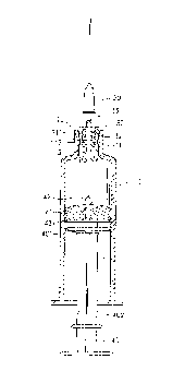
Fig. 1 is a sectional view showing a safety
hypodermic syringe according to the present invention;
Fig. 2 shows the plunger moved forwards to
the inside of the barrel, and the retainer rod of the
rubber stopper forced into engagement with the retaining
hole of the needle holder according to the present
invention;
Fig. 3 shows the needle holder and the needle
cannula received on the inside of the barrel according
to the present invention;
Fig 4 shows the connecting tip of the
connecting member broken, and the plunger disconnected
from the connecting member according to the present
invention;

2 ~ 8~ 8~3
Fig. 5 shows the plunger inserted into the
front neck of the barrel, and the needle cannula
deformed according to the present invention.
DETAILED DESCRIPTION OF T~ PREFERR~n EMBODIMENT
Referring to Figure 1, the barrel, referenced
by 10, comprises an inside flange 11 raised around the
inside wall of the front neck 12 thereof. A needle
holder 30 is inserted into the front neck 12 of the
barrel 10 and retained in place by the inside flange 11
to hold the needle cannula, referenced by 20. The
inside flange 11 has a front sloping wall 111 of small
slope and a rear sloping wall 112 of different angles.
The front sloping wall 111 and the rear sloping wall 112
are so designed that the needle holder 30 can be pulled
backwards into the inside of the barrel 10 but cannot be
pushed forwardly out of the front neck 12 of the barrel
10. The needle holder 30 comprises a longitudinal
center through hole 33, which imparts a passage between
the needle cannula 20 and the holding space of the
barrel 10, an inner thread 32 around the longitudinal
center through hole 33 for mounting the needle cannula
20, and an arrowhead-like retaining hole 31 at the rear
end of the longitudinal center through hole 33 remote
from the needle cannula 20. The plunger, referenced by

21 83823
40, ha~ a locating groove 402 around the periphery near
the rear end. The front end of the plunger 40 is
connected to a connecting member 43. The connecting
member 43 has a connecting tip 401 connected to the
front end of the plunger 40. The connecting tip 401 can
be easily broken so that the plunger 40 can be
disconnected from the connecting member 43. The
connecting member 43 may be variously shaped. As an
e~ample of the present invention, the connecting member
43 has a plurality of circular flange around the
periphery fitting the inner diameter of the barrel 10.
A rubber stopper 41 is fixedly secured to the connecting
member 43 at the front side remote from the plunger 40.
The rubber stopper 41 has an arrowhead-like retainer rod
42 which can be forced into engagement with the
arrowhead-like retaining hole 31 of the needle holder
30.
Referring to Figures from 2 to 5, when the
plunger 40 is moved forwards to the inside of the barrel
10, the liquid medicine is completely squeezed out of
the barrel 10 through the needle cannula 20, and at the
same time the arrowhead-like retainer rod 42 of the
rubber stopper 41 is forced into engagement with the
arrowhead-like retaining hole 31 of the needle holder 30
(see Figure 2). When the plunger 40 is pulled

21 8~23
. ~
backwards, the needle holder 30 with the needle cannula
20 are pulled backwards to the inside of the barrel 10
(see Figure 3). Because the arrowhead-like retaining
hole 31 slightly slopes from the longitudinal center
Saxis of the needle holder 30, the needle holder 30 and
the needle cannula 20 tilt when they are moved to the
inside of the barrel 10. When the connecting member 43
is stopped at the rear end of the barrel 10, the plunger
40 is disconnected from the connecting member 43 by
10breaking the connecting tip 401 (see Figure 4). Then,
the plunger 40 is inserted into the front neck 12 of the
barrel 10 to deform the needle cannula 20. ~hen the
~ needle cannula 20 is deformed, the locating groove 402
of the plunger 40 is engaged with the inside flange 11
15of the front neck 12 of the barrel 10, and therefore the
plunger 40 is firmly retained to the front neck 12 of
the barrel 10.
It is to be understood that the drawings are
designed for purposes of illustration only, and are not
20intended as a definition of the limits and scope of the
invention disclosed For example, the retaining hole 31
can be made of conical shape, or in the form of a
triangular pyramid; the profile of the front end of the
retainer rod 42 fits the configuration of the retaining

2~ 83823
hole 31 for positive engagement.

Representative Drawing
A single figure which represents the drawing illustrating the invention.
Administrative Status

2024-08-01:As part of the Next Generation Patents (NGP) transition, the Canadian Patents Database (CPD) now contains a more detailed Event History, which replicates the Event Log of our new back-office solution.

Please note that "Inactive:" events refers to events no longer in use in our new back-office solution.

For a clearer understanding of the status of the application/patent presented on this page, the site Disclaimer , as well as the definitions for Patent , Event History , Maintenance Fee  and Payment History  should be consulted.

Event History

Description Date
Inactive: Cover page published 2000-12-20
Time Limit for Reversal Expired 2000-08-21
Application Not Reinstated by Deadline 2000-08-21
Letter Sent 1999-08-27
Deemed Abandoned - Failure to Respond to Maintenance Fee Notice 1999-08-23
Reinstatement Requirements Deemed Compliant for All Abandonment Reasons 1999-08-23
Deemed Abandoned - Failure to Respond to Maintenance Fee Notice 1998-08-21
Application Published (Open to Public Inspection) 1998-02-22

Abandonment History

Abandonment Date Reason Reinstatement Date
1999-08-23
1998-08-21

Maintenance Fee

The last payment was received on 1999-08-23

Note : If the full payment has not been received on or before the date indicated, a further fee may be required which may be one of the following

  • the reinstatement fee;
  • the late payment fee; or
  • additional fee to reverse deemed expiry.

Patent fees are adjusted on the 1st of January every year. The amounts above are the current amounts if received by December 31 of the current year.
Please refer to the CIPO Patent Fees web page to see all current fee amounts.

Fee History

Fee Type Anniversary Year Due Date Paid Date
Reinstatement 1999-08-23
MF (application, 2nd anniv.) - small 02 1998-08-21 1999-08-23
Owners on Record

Note: Records showing the ownership history in alphabetical order.

Current Owners on Record
LONG-HSIUNG CHEN
Past Owners on Record
None
Past Owners that do not appear in the "Owners on Record" listing will appear in other documentation within the application.
Documents

To view selected files, please enter reCAPTCHA code :


To view images, click a link in the Document Description column. To download the documents, select one or more checkboxes in the first column and then click the "Download Selected in PDF format (Zip Archive)" or the "Download Selected as Single PDF" button.

List of published and non-published patent-specific documents on the CPD .

If you have any difficulty accessing content, you can call the Client Service Centre at 1-866-997-1936 or send them an e-mail at CIPO Client Service Centre.


Document
Description 
Date
(yyyy-mm-dd) 
Number of pages   Size of Image (KB) 
Representative drawing 1998-03-03 1 6
Representative drawing 2000-12-12 1 6
Claims 1996-11-19 3 79
Drawings 1996-11-19 3 63
Description 1996-11-19 7 197
Abstract 1996-11-19 1 18
Reminder of maintenance fee due 1998-04-21 1 111
Courtesy - Abandonment Letter (Maintenance Fee) 1998-09-20 1 184
Courtesy - Abandonment Letter (Maintenance Fee) 1999-09-19 1 187
Notice of Reinstatement 1999-08-26 1 172
Fees 1999-08-22 1 35