Sélection de la langue

Search

Sommaire du brevet 2183823 

Énoncé de désistement de responsabilité concernant l'information provenant de tiers

Une partie des informations de ce site Web a été fournie par des sources externes. Le gouvernement du Canada n'assume aucune responsabilité concernant la précision, l'actualité ou la fiabilité des informations fournies par les sources externes. Les utilisateurs qui désirent employer cette information devraient consulter directement la source des informations. Le contenu fourni par les sources externes n'est pas assujetti aux exigences sur les langues officielles, la protection des renseignements personnels et l'accessibilité.

Disponibilité de l'Abrégé et des Revendications

L'apparition de différences dans le texte et l'image des Revendications et de l'Abrégé dépend du moment auquel le document est publié. Les textes des Revendications et de l'Abrégé sont affichés :

  • lorsque la demande peut être examinée par le public;
  • lorsque le brevet est émis (délivrance).
(12) Demande de brevet: (11) CA 2183823
(54) Titre français: SERINGUE HYPODERMIQUE AVEC DISPOSITIF DE SECURITE
(54) Titre anglais: STRUCTURE OF SAFETY HYPODERMIC SYRINGE
Statut: Réputée abandonnée et au-delà du délai pour le rétablissement - en attente de la réponse à l’avis de communication rejetée
Données bibliographiques
Abrégés

Abrégé anglais


A safety hypodermic syringe in which the
needle holder has an arrowhead-like rear retaining hole;
the rubber stopper has an arrowhead-like retainer rod
that can be forced into engagement with the retaining
hole of the needle holder for permitting the needle
holder with the needle cannula to be pulled backwards to
the inside of the barrel by the plunger; the plunger can
be disconnected from the rubber stopper and then
inserted into the front end of the barrel to deform the
needle cannula when the needle cannula is received on
the inside of the barrel.

Revendications

Note : Les revendications sont présentées dans la langue officielle dans laquelle elles ont été soumises.


THE EMBODIMENTS OF THE INVENTION IN WHICH AN EXCLUSIVE
PROPERTY OR PRIVILEGE IS CLAIMED ARE DEFINED AS FOLLOWS:
1. A safety hypodermic syringe comprising a
barrel having a front neck and an inside flange inside
said front neck, a needle holder inserted into said
front neck of said barrel and retained in place by said
inside flange of said front neck of said barrel, a
needle cannula fastened to said needle holder, a plunger
moved in said barrel, a rubber stopper connected to said
plunger by a connecting member, wherein said inside
flange of said front neck of said barrel has a front
sloping wall of small slope and a rear sloping wall of
different angles for permitting said needle holder to be
pulled backwards to an inside of said barrel and for
stopping said needle holder from being forced forwards
out of said front neck of said barrel; said needle
holder comprises a longitudinal center through hole,
which imparts a passage between said needle cannula and
said barrel, an inner thread around said longitudinal
center through hole for mounting said needle cannula,
and a rear retaining hole at one end of said
longitudinal center through hole remote from said needle
cannula; said connecting member has a connecting tip
connected to said plunger that can be broken to let said
plunger be disconnected from said connecting member;
said rubber stopper has a retainer rod at a front end
thereof fitting said retaining hole of said needle

holder, said retaining rod being forced into engagement
with said retaining hole of said needle holder when said
rubber stopper is moved to said front neck of said
barrel by said plunger, for permitting said needle
holder with said needle cannula to be pulled backwards
to said inside of said barrel by said plunger; said
plunger can be inserted into said front neck of said
barrel to deform said needle cannula when said needle
holder and said needle cannula are moved to said inside
of said barrel and said plunger is disconnected from the
connecting tip of said connecting member; said plunger
has a locating groove around a periphery of said plunger
for engagement with said inside flange of said front
neck of said barrel when it is inserted into front end
of said barrel to deform said needle cannula.
2. The safety hypodermic syringe of claim 1
wherein said retaining hole of said needle holder is
made of arrowhead-like shape, and slopes from the
longitudinal center axis of said needle holder in one
direction.
3. The safety hypodermic syringe of claim 1
wherein said retainer rod of said rubber stopper is
shaped like an arrowhead fitting said retaining hole of

said needle holder.
4. The safety hypodermic syringe of claim 1
wherein said connecting member has at least one circular
flange around said periphery fitting an inner diameter
of said barrel.

Description

Note : Les descriptions sont présentées dans la langue officielle dans laquelle elles ont été soumises.

~ ~ 2183823
STRUCTURE OF SA~FTY HYPnn~MTc SYRINGE
BACRGROUND OF THE INVENTIQN
The present invention relates to hypodermic
syringes, and relates more particularly to a safety
hypodermic syringe which permits the needle holder with
the needle cannula to be pulled backwards to the inside
of the barrel by the plunger after injection, and
permits the plunger to be disconnected from the rubber
stopper and then inserted into the front end of the
barrel to deform the needle cannula inside the barrel
The needle cannula of a hypodermic syringe
must be damaged after its use, and then properly
disposed of. Taiwan patent publication no. 210509
discloses a safety hypodermic syringe which permits the
needle cannula to be pulled backwards to the inside of
the barrel after its use. However, this structure of
safety hypodermic syringe must be used with a specially
designed needle cannula. Another drawback of this
structure of safety hypodermic syringe is that the
deformed needle cannula will still project out of the
barrel if the needle cap is disconnected Taiwan
patent publication no. 212301 discloses another
structure of safety hypodermic syringe. This structure
of safety hypodermic syringe still cannot be used with

~ ~1 83~23
regular commercially available needle cannula. Taiwan
patent application no. 822180~9 discloses still another
structure of safety hypodermic syringe. This structure
of safety hypodermic syringe is designed to adapt any of
a variety of commercially available needle cannulas.
However, because the needle holder has an opening which
is not sealed after the needle cannula has been moved to
the inside of the barrel, the needle cannula will still
project out of the barrel.
SUMMARY OF THE INV~NTION
The present invention has been accomplished
to provide a safety hypodermic syringe which eliminates
the aforesaid drawbacks. According to one aspect of
the present invention, the needle holder has an
arrowhead-like retaining hole; the rubber stopper has
an arrowhead-like retainer rod that can be forced into
engagement with the retaining hole of the needle holder
for permitting the needle holder with the needle cannula
to be pulled backwards to the inside of the barrel by
the plunger. According to another aspect of the
present invention, the plunger is connected to the
rubber stopper by a connecting member, which has a
connecting tip connected to the plunger that can be
broken to let the plunger be disconnected from the

8 ~ 3
rubber stopper and then inserted into the front end of
the barrel to deform the needle calmula when the needle
cannula is received on the inside of the barrel.
According to still another aspect of the present
invention, the front end of the barrel has an inside
flange which defines a front sloping wall and a rear
sloping wall of different angles such that the needle
holder can be moved backwards to the inside of the
barrel, but is stopped from being moved forwards to the
outside of the front end of the barrel.
BRIEF D~sr~Tp~IoN OF T~E D~AWIN~S
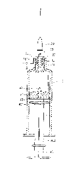
Fig. 1 is a sectional view showing a safety
hypodermic syringe according to the present invention;
Fig. 2 shows the plunger moved forwards to
the inside of the barrel, and the retainer rod of the
rubber stopper forced into engagement with the retaining
hole of the needle holder according to the present
invention;
Fig. 3 shows the needle holder and the needle
cannula received on the inside of the barrel according
to the present invention;
Fig 4 shows the connecting tip of the
connecting member broken, and the plunger disconnected
from the connecting member according to the present
invention;

2 ~ 8~ 8~3
Fig. 5 shows the plunger inserted into the
front neck of the barrel, and the needle cannula
deformed according to the present invention.
DETAILED DESCRIPTION OF T~ PREFERR~n EMBODIMENT
Referring to Figure 1, the barrel, referenced
by 10, comprises an inside flange 11 raised around the
inside wall of the front neck 12 thereof. A needle
holder 30 is inserted into the front neck 12 of the
barrel 10 and retained in place by the inside flange 11
to hold the needle cannula, referenced by 20. The
inside flange 11 has a front sloping wall 111 of small
slope and a rear sloping wall 112 of different angles.
The front sloping wall 111 and the rear sloping wall 112
are so designed that the needle holder 30 can be pulled
backwards into the inside of the barrel 10 but cannot be
pushed forwardly out of the front neck 12 of the barrel
10. The needle holder 30 comprises a longitudinal
center through hole 33, which imparts a passage between
the needle cannula 20 and the holding space of the
barrel 10, an inner thread 32 around the longitudinal
center through hole 33 for mounting the needle cannula
20, and an arrowhead-like retaining hole 31 at the rear
end of the longitudinal center through hole 33 remote
from the needle cannula 20. The plunger, referenced by

21 83823
40, ha~ a locating groove 402 around the periphery near
the rear end. The front end of the plunger 40 is
connected to a connecting member 43. The connecting
member 43 has a connecting tip 401 connected to the
front end of the plunger 40. The connecting tip 401 can
be easily broken so that the plunger 40 can be
disconnected from the connecting member 43. The
connecting member 43 may be variously shaped. As an
e~ample of the present invention, the connecting member
43 has a plurality of circular flange around the
periphery fitting the inner diameter of the barrel 10.
A rubber stopper 41 is fixedly secured to the connecting
member 43 at the front side remote from the plunger 40.
The rubber stopper 41 has an arrowhead-like retainer rod
42 which can be forced into engagement with the
arrowhead-like retaining hole 31 of the needle holder
30.
Referring to Figures from 2 to 5, when the
plunger 40 is moved forwards to the inside of the barrel
10, the liquid medicine is completely squeezed out of
the barrel 10 through the needle cannula 20, and at the
same time the arrowhead-like retainer rod 42 of the
rubber stopper 41 is forced into engagement with the
arrowhead-like retaining hole 31 of the needle holder 30
(see Figure 2). When the plunger 40 is pulled

21 8~23
. ~
backwards, the needle holder 30 with the needle cannula
20 are pulled backwards to the inside of the barrel 10
(see Figure 3). Because the arrowhead-like retaining
hole 31 slightly slopes from the longitudinal center
Saxis of the needle holder 30, the needle holder 30 and
the needle cannula 20 tilt when they are moved to the
inside of the barrel 10. When the connecting member 43
is stopped at the rear end of the barrel 10, the plunger
40 is disconnected from the connecting member 43 by
10breaking the connecting tip 401 (see Figure 4). Then,
the plunger 40 is inserted into the front neck 12 of the
barrel 10 to deform the needle cannula 20. ~hen the
~ needle cannula 20 is deformed, the locating groove 402
of the plunger 40 is engaged with the inside flange 11
15of the front neck 12 of the barrel 10, and therefore the
plunger 40 is firmly retained to the front neck 12 of
the barrel 10.
It is to be understood that the drawings are
designed for purposes of illustration only, and are not
20intended as a definition of the limits and scope of the
invention disclosed For example, the retaining hole 31
can be made of conical shape, or in the form of a
triangular pyramid; the profile of the front end of the
retainer rod 42 fits the configuration of the retaining

2~ 83823
hole 31 for positive engagement.

Dessin représentatif
Une figure unique qui représente un dessin illustrant l'invention.
États administratifs

2024-08-01 : Dans le cadre de la transition vers les Brevets de nouvelle génération (BNG), la base de données sur les brevets canadiens (BDBC) contient désormais un Historique d'événement plus détaillé, qui reproduit le Journal des événements de notre nouvelle solution interne.

Veuillez noter que les événements débutant par « Inactive : » se réfèrent à des événements qui ne sont plus utilisés dans notre nouvelle solution interne.

Pour une meilleure compréhension de l'état de la demande ou brevet qui figure sur cette page, la rubrique Mise en garde , et les descriptions de Brevet , Historique d'événement , Taxes périodiques et Historique des paiements devraient être consultées.

Historique d'événement

Description Date
Inactive : Page couverture publiée 2000-12-20
Le délai pour l'annulation est expiré 2000-08-21
Demande non rétablie avant l'échéance 2000-08-21
Lettre envoyée 1999-08-27
Réputée abandonnée - omission de répondre à un avis sur les taxes pour le maintien en état 1999-08-23
Exigences de rétablissement - réputé conforme pour tous les motifs d'abandon 1999-08-23
Réputée abandonnée - omission de répondre à un avis sur les taxes pour le maintien en état 1998-08-21
Demande publiée (accessible au public) 1998-02-22

Historique d'abandonnement

Date d'abandonnement Raison Date de rétablissement
1999-08-23
1998-08-21

Taxes périodiques

Le dernier paiement a été reçu le 1999-08-23

Avis : Si le paiement en totalité n'a pas été reçu au plus tard à la date indiquée, une taxe supplémentaire peut être imposée, soit une des taxes suivantes :

  • taxe de rétablissement ;
  • taxe pour paiement en souffrance ; ou
  • taxe additionnelle pour le renversement d'une péremption réputée.

Les taxes sur les brevets sont ajustées au 1er janvier de chaque année. Les montants ci-dessus sont les montants actuels s'ils sont reçus au plus tard le 31 décembre de l'année en cours.
Veuillez vous référer à la page web des taxes sur les brevets de l'OPIC pour voir tous les montants actuels des taxes.

Historique des taxes

Type de taxes Anniversaire Échéance Date payée
Rétablissement 1999-08-23
TM (demande, 2e anniv.) - petite 02 1998-08-21 1999-08-23
Titulaires au dossier

Les titulaires actuels et antérieures au dossier sont affichés en ordre alphabétique.

Titulaires actuels au dossier
LONG-HSIUNG CHEN
Titulaires antérieures au dossier
S.O.
Les propriétaires antérieurs qui ne figurent pas dans la liste des « Propriétaires au dossier » apparaîtront dans d'autres documents au dossier.
Documents

Pour visionner les fichiers sélectionnés, entrer le code reCAPTCHA :


Pour visualiser une image, cliquer sur un lien dans la colonne description du document. Pour télécharger l'image (les images), cliquer l'une ou plusieurs cases à cocher dans la première colonne et ensuite cliquer sur le bouton "Télécharger sélection en format PDF (archive Zip)" ou le bouton "Télécharger sélection (en un fichier PDF fusionné)".

Liste des documents de brevet publiés et non publiés sur la BDBC .

Si vous avez des difficultés à accéder au contenu, veuillez communiquer avec le Centre de services à la clientèle au 1-866-997-1936, ou envoyer un courriel au Centre de service à la clientèle de l'OPIC.


Description du
Document 
Date
(aaaa-mm-jj) 
Nombre de pages   Taille de l'image (Ko) 
Dessin représentatif 1998-03-03 1 6
Dessin représentatif 2000-12-12 1 6
Revendications 1996-11-19 3 79
Dessins 1996-11-19 3 63
Description 1996-11-19 7 197
Abrégé 1996-11-19 1 18
Rappel de taxe de maintien due 1998-04-21 1 111
Courtoisie - Lettre d'abandon (taxe de maintien en état) 1998-09-20 1 184
Courtoisie - Lettre d'abandon (taxe de maintien en état) 1999-09-19 1 187
Avis de retablissement 1999-08-26 1 172
Taxes 1999-08-22 1 35