Note: Descriptions are shown in the official language in which they were submitted.
CA 02184126 2005-11-28
1
AMMONIA PRODUCTION WITH ENRICHED AIR REFORMING
AND NITROGEN INJECTION INTO THE SYNTHESIS LOOP
Field of the Invention
The present invention is directed to a process for the manufacture of
ammonia using enriched air reforming and injection of nitrogen into the
synthesis loop, and more particularly to a retrofit method for increasing the
production capacity of an ammonia plant by installing air enrichment and
nitrogen injection capabilities.
Background of the Invention
Many plants have been built for producing ammonia. Typically, a
hydrocarbon feedstock such as natural gas is reformed in a front end of the
plant to produce a synthesis gas containing hydrogen and nitrogen. The
synthesis gas is then converted in a synthesis loop to form ammonia. Many
plants operate with a synthesis loop based on magnetite catalyst in the
ammonia synthesis converters. These reactors generally operate with a
hydrogen to nitrogen ratio (HN ratio) in the feed of about 3. More recently,
plants have been built using a more efficient catalyst which is based on a
platinum group metal such as ruthenium supported on a graphite-containing
carbon as in, for example, U.S. Patent 4,568,530. Using the ruthenium
catalyst, the HN ratio is desirably less than 3.
Technological advances have also been made in the front end of the
ammonia plant for making the synthesis gas. Conventionally, plants were
built with primary and secondary reformers. In the primary reformer, steam
and natural gas is reacted at an elevated temperature in a fired furnace. In
the secondary reformer, air is added to the effluent from the primary reformer
and the mixture reacted adiabatically using the combustion reaction with
oxygen in the air as a source of heat for the reforming reaction. The effluent
CA 02184126 2005-11-28
2
from the secondary reformer is then shift converted to favor the formation of
hydrogen. A significant change in more recent plants has been the use of
autothermal steam reforming wherein the effluent from the secondary or
autothermal reformer is used as the primary source of heat for the primary
reformer (or more accurately a reforming exchanger), as in for example, U.S.
Patent 5,011,625. In either case, the HN ratio is controlled by controlling
the
amount of nitrogen injected with the air to the secondary or autothermal
reformer. In some instances, oxygen-enriched air has also been supplied to
the secondary or autothermal reformer as an economic tradeoff between the
cost of the oxygen unit and the benefits of using oxygen-enriched air in the
secondary/autothermal reformer feed.
Frequently, it is desired to increase the capacity of an existing
ammonia plant. The production capacity of the synthesis loop can usually be
relatively easily increased by installing high activity ruthenium catalyst
converter capability and/or modifying the synthesis gas compressor to handle
additional synthesis gas. Increasing the capacity of the front end has been
more problematic. Even though the primary and secondary reformers may
have additional capacity, or can be easily modified to increase capacity, the
air compressor, shift converters and/or COZ removal system are usually
already constrained at maximum capacity. Increased capacity in the front end
of the plant can require the installation of parallel equipment such as
another
air compressor and additional C02 removal equipment, a costly option. Thus,
a need exists for a retrofit capable of increasing the capacity of an ammonia
plant without installing parallel equipment.
Summary of the Invention
The present invention is an ammonia plant which uses enriched air
reforming coupled with strategic injection of nitrogen into the synthesis
loop.
CA 02184126 2005-11-28
3
An oxygen-rich stream is injected into a secondary or autothermal reformer of
an ammonia plant to facilitate reforming of natural gas or other reformable
hydrocarbon feed. A nitrogen-rich stream is injected into the make-up gas or
ammonia synthesis loop. This strategic mixing point of the nitrogen has the
advantage of bypassing the conventional processing of excess nitrogen in the
front end of the ammonia plant, and providing the nitrogen required for the
ammonia conversion. By injecting the nitrogen into the make-up gas or
synthesis loop, the nitrogen bypasses the front end which results in a lower
front end pressure drop than would otherwise result and reduces equipment
costs. The invention is particularly applicable to the retrofit of an existing
plant, where this process can eliminate significant constraints to higher
production capacity in the front end of the ammonia plant. The strategic
mixing of nitrogen in the make-up gas or synthesis loop provides flexibility
of
operation, hydrogen-to-nitrogen ratio (HN ratio) control and maximizes the
performance of ammonia synthesis catalyst. This process is applicable to
conventional magnetite catalyst systems, as well as catalyst systems based
on a platinum group metal on a graphite-containing carbon support.
Broadly, this invention provides a process plant for ammonia synthesis,
comprising: (a) means for separating air into oxygen-rich and nitrogen-rich
streams; (b) means for mixing air with the oxygen-rich stream from
separation means (a) to form an oxygen-enriched stream containing
- 40 mole percent oxygen; (c) means for injecting the oxygen-enriched
stream from mixing means (b) into an autothermal reformer of a syngas unit
including a primary reformer upstream from the autothermal reformer and a
25 downstream shift converter, C02 removal unit and methanator, to produce a
syngas stream; (d) means for supplying the syngas stream from injection
means (c) and the nitrogen-rich stream from separation means (a) as makeup
gas to an ammonia synthesis loop; (e) means for operating the ammonia
CA 02184126 2005-11-28
4
synthesis loop to (1 ) convert nitrogen and hydrogen in an ammonia synthesis
reactor feed stream to form an ammonia-rich stream, (2) recover ammonia
from the ammonia rich stream to form a recycle gas stream, (3) remove a
purge stream from the synthesis loop, (4) recover a hydrogen-rich gas from
the purge stream, and (5) combine the hydrogen-rich gas with the recycle
stream and the makeup gas from supply means (d) to form the ammonia
synthesis reactor feed stream.
In another aspect, the invention provides a retrofit method for
increasing the production capacity of an ammonia plant having a front end
including in series primary and secondary reformers and high and low
temperature shift converter for reacting a hydrocarbon feed, steam and air to
form a make-up syngas stream comprising hydrogen and nitrogen at about
design stoichiometry, and a synthesis loop wherein a recycle syngas stream
is combined with a make-up gas to form a syngas feed to ammonia
converters. The method includes enriching air supplied to the secondary
reformer with oxygen and increasing hydrogen content of the make-up gas
substantially above the design stoichiometry. As a second step, a
substantially pure nitrogen stream is supplied to the synthesis loop to obtain
a
desired hydrogen to nitrogen ratio in the syngas feed to the ammonia
converters.
The retrofit can include installing an air separation unit to form
oxygen-rich and nitrogen-rich streams, wherein the oxygen-rich stream
is added to air in the enrichment step, and wherein the nitrogen-rich stream
is used as a source for the substantially pure
2i84i2~
95-05441KEL-45
8114/96
nitrogen stream. Preferably, the existing synthesis loop capacity of
the ammonia plant, prior to the retrofit, exceeds the existing front end
capacity. In this manner, the front end capacity of the plant is
increased by the retrofit to meet some or all of the excess capacity of
5 the synthesis loop. Alternatively, the synthesis loop can be modified
to increase the capacity to exceed the capacity of the front end
existing before the retrofit. In this manner, the overall capacity of the
ammonia plant can be increased.
When the ammonia plant includes a methanator for removing
carbon oxides to condition the make-up syngas stream for the
synthesis loop, the nitrogen supply step preferably comprises
injecting a nitrogen stream into the make-up syngas stream upstream
from the methanator. Any o~rygen compounds in the nitrogen stream
are removed in the methanator.
In another embodiment, the nitrogen stream is essentially free
of oxygen and oxygen compounds and can be added directly to the
make-up syngas stream, or into the syngas feed, depending on the
capacity of the existing make-up gas compressor to handle the
additional nitrogen. Where the make-up syngas compressor cannot
handle the additional nitrogen stream, the nitrogen stream can be
compressed with a separate compressor and injected into the syngas
feed.
In a preferred embodiment, the present invention provides a
retrofit method for increasing the production of an ammonia plant
having (1) a front end including a primary reformer, a secondary
reformer, an air compressor, and a C02 removal unit for reacting a
hydrocarbon feed stream with steam and compressed air to produce
a make-up syngas stream having a design HN ratio at a preexisting
capacity, and (2) a synthesis loop wherein a recycle syngas stream is
I~ 95-0544IKEL-45 ~ 1 ~ 4 ~ 2 6
8/14196
6
combined with the make-up syngas stream to form a syngas feed to
ammonia converters for producing ammonia at a preexisting capacity.
The retrofit method includes the steps of: installing an air separation
unit to produce oxygen-rich and nitrogen-rich streams; injecting the
oxygen-rich stream into the compressed air and operating the front
end at an increased capacity relative to its preexisting capacity
wherein a raw syngas stream from the C02 removal unit has an
increased HN ratio relative to the design ratio; supplying the nitrogen-
rich stream to the synthesis loop; and modifying the synthesis loop to
increase the ammonia capacity of the synthesis loop. The injection
step preferably forms an oxygen-enriched air stream for feed to the
secondary reformer containing from 25 to 40 volume percent oxygen.
The oxygen-rich stream which is used to enrich the air stream
preferably contains from 40 to 100 volume percent oxygen. The
nitrogen-rich stream preferably contains less than 1 volume percent
oxygen, is injected into the raw syngas stream, and the retrofit
method preferably includes passing the nitrogen-enriched raw syngas
stream through a methanator to form the make-up syngas stream
essentially free of oxygen and oxygen-containing compounds.
Alternatively, the nitrogen-rich stream is essentially free of oxygen
and the nitrogen rich stream is injected into the makeup syngas
stream downstream from a methanator. As another alternative where
the nitrogen-rich stream is essentially free of oxygen, the nitrogen-rich
stream is injected into the syngas feed to the ammonia converters.
The modification of the synthesis loop can include the installation of
ammonia conversion capacity based on high activity catalyst
comprising a platinum group metal supported on graphite-containing
carbon.
CA 02184126 2005-11-28
7
Brief Description of the Drawings
Fig. 1 is a schematic illustration of an enriched air/nitrogen injection of
ammonia process according the present invention which includes an air
separation unit.
Fig. 2 is a schematic process flow diagram for a retrofit ammonia plant
according to one embodiment of the present invention.
Detailed Description of the Invention
In the ammonia production scheme of the present invention,
oxygen-enriched air is supplied to the secondary reformer in the front end of
the plant to increase hydrogen production, and nitrogen is added downstream
to maintain the desired stoichiometry for the ammonia synthesis. With
reference to Fig. 1, the ammonia process 10 includes an air separation
step 12 in which air supplied via stream 11A, is separated into oxygen-rich
and nitrogen-rich streams 14 and 16. The oxygen-rich stream 14 is supplied
along with air stream 11 B to an air compression step 18 to produce an
oxygen-enriched air stream 20. The enriched air stream 20 is supplied to a
synthesis gas preparation step 22 in which a hydrocarbon feed such as
natural gas is reformed with steam using the oxygen-enriched air stream 20
for secondary reforming. The syngas preparation step 22 yields a raw
make-up syngas stream 24. The raw make-up syngas stream 24 is relatively
lean in nitrogen, and the additional nitrogen required is supplied by
nitrogen-rich stream 16 to the synthesis gas purification/ammonia synthesis
step 26 to yield an ammonia product stream 28.
The air separation step 12 is effected using conventional techniques
for separating air into nitrogen-rich and oxygen-rich streams, such
as, for example, cryogenic distillation, pressure-swing absorption or the
like. Typically, cryogenic distillation is preferred for
~184i26
95-05441KEL-45
8114196
8
economic reasons. Air separation can be avoided if oxygen-rich and
nitrogen-rich streams of suitable purity and quantity are otherwise
available.
When cryogenic distillation is used to separate air into oxygen
and nitrogen streams, the purity of the oxygen-rich stream is not
critical since it will be used in the air compression step 18 to supply
the enriched air stream 20 to the syngas preparation step 22. Oxygen
streams containing as little as 40 volume percent oxygen up to 100
volume percent oxygen of high purity are suitable, but it is preferable
to use an oxygen-rich stream 14 with an oxygen content of from 50 to
80 volume percent in sufficient quantities to produce an enriched atr
stream 20 containing from 25 to 40 volume percent oxygen, more
preferably from about 26 to about 36 volume percent oxygen.
Depending on how the nitrogen-rich stream 16 is injected into the
purificationlsynthesis step 26, the purity thereof, particularly the
content of oxygen and oxygen-containing compounds, is generally an
important consideration. Since the nitrogen-rich stream 16 is not
processed in the reforming reactions which would normally remove
oxygen, care must be taken to avoid the deleterious effects that
oxygen in the nitrogen-rich stream 16 could otherwise have on the
catalyst used in the synthesis step 26 for ammonia conversion.
Preferably, the nitrogen-rich stream has a low oxygen content to
facilitate purification of the nitrogen-rich stream 16. Less than 1
volume percent oxygen in the nitrogen-rich stream 16 is preferred,
and oxygen contents below 1,000 ppmv are particularly
advantageous, especially below 5 ppmv. In one preferred
arrangement, the air separation 12 involves the cryogenic
fractionation of air in a configuration typically employed in the air
separation arts for the production of high purity nitrogen essentially
CA 02184126 2005-11-28
9
free of oxygen, and a reject oxygen product containing 50-80 volume percent
oxygen.
The equipment and techniques used for compressing air in the air
compression step 18 are well known in the art. The enriched oxygen
stream 14 can be introduced at an ambient air intake for a conventional air
compressor, or it can be introduced between stages of the compressor.
Frequently, the air compression step 18 in existing plants is near maximum of
the capacity of the air compression equipment. Thus, introducing the
oxygen-rich stream 14 means that less ambient air 11 B is used in the
compression step 18 as this is replaced by the oxygen-rich stream 14.
The syngas preparation step 22 is performed using conventional
equipment designed for this purpose. Typically, the syngas preparation
step 22 will involve the operation of a primary reformer, a secondary reformer
and high and low temperature shift converters. The primary reformer typically
heats natural gas 23 and steam 25 to partially reform the natural gas 23. This
is usually done in a fired furnace, but as used herein the term "primary
reformer" generically encompasses the so-called reforming exchanger as
well. The partially reformed effluent from the primary reformer is then mixed
with the enriched air stream 20 and reacted adiabatically to complete the
reforming reaction. In some ammonia plants, a so-called autothermal
reformer is used to adiabatically react the air and effluent from the primary
reformer and supply heat to the primary reformer (reforming exchanger). As
used herein, the term "secondary reformer," and terms of similar import, are
used generically to include the autothermal reformer, even though most of the
natural gas may actually be reformed in the autothermal reformer. Carbon
monoxide in the effluent from the secondary reformer is typically converted
95-05441KEL-45 ~ .p g ~ ~ 2 ~
8/14/96
according to the shift reaction with steam to form carbon dioxide and
additional hydrogen. The effluent from the secondary reformer, or the
shift converters, andlor C02 ~~emoval equipment, if employed, forms
the make-up syngas stream 24.
5 The performance of the syngas preparation step 22 according
to the present invention results in the formation of a generally
hydrogen-rich, nitrogen-lean make-up syngas stream 24. Although
the volume of the oxygen-enriched air stream 20 is similar to the
volume of compressed air supplied without the enrichment, the
10 presence of the additional oxygen allows the reforming of more
hydrocarbon in the secondary reformer. The processing of more
natural gas results in the formation of more hydrogen, but less
nitrogen is introduced into the secondary reformer when the oxygen-
enriched air stream 20 is employed. To produce the same quantity of
hydrogen at the same HN ratio prior to the use of enriched air would
result in a substantially higher volume of gas being processed in the
reformers and shift converters; however, in the present invention, the
volume of gas processed in the reformers, shift converters and C02
removal equipment is not substantially higher. Thus, more hydrogen
can be produced with a relatively low increase of pressure losses
through the reformers and shift converters. On the other hand, the
additional oxygen in the enriched air stream 20 relative to
compressed air can result in more heat being produced in the effluent
from the secondary reformer. This can advantageously produce
additional steam from the heat recovery section typically found
downstream from the secondary reformer and shift converters.
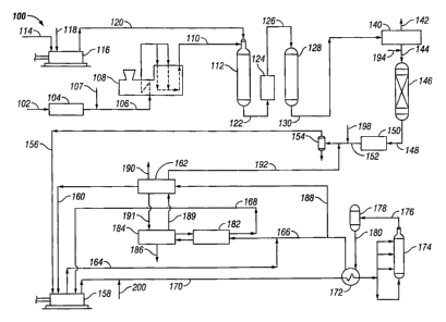
An example of an ammonia plant X00 using conventional
primary and secondary reforming and a magnetite ammonia reactor
retrofitted for secondary reforming with enriched air, downstream
CA 02184126 2005-11-28
11
nitrogen injection, and operation of a high activity ammonia converter in
series
with the magnetite converter, is shown in Fig. 2. A reformable hydrocarbon
feedstock such as natural gas is supplied via line 102 to desulfurizer 104 for
removal of sulfur, for example, by adsorption on activated carbon, by reaction
with zinc oxide to remove H2S, mercaptans and chlorine, or another sulfur
removal technique known in the art. The desulfurized feedstock is obtained
from the desulfurizer in line 106 into which is introduced steam via line 107
for
reforming in primary reformer 108. The primary reformer 108 is
conventionally fired and produces a partially reformed effluent in line 110.
The effluent in line 110 is fed to secondary reformer 112. Air is supplied via
line 114 to compressor 116 along with an oxygen-rich stream 118 to form an
oxygen-enriched compressed air stream 120 which is also added to the
secondary reformer 112 for reaction with the partially reformed feedstock from
line 110. The effluent from the secondary reformer 112 is passed via line 122
to conventional heat recovery section 124 and then via line 126 to shift
converter 128. The shift converter 128 can include high and low temperature
shift converters in series which are conventional in the art for reacting
carbon
monoxide and steam to form hydrogen and carbon dioxide.
The effluent from the shift converter 128 is passed via line 130
to carbon dioxide removal system 140. The carbon dioxide removal
system can be any one of the C02 removal systems well known in
the art, such as, for example, a monoethanolamine solvent system,
promoted monoethanolamine solvent system, a methyldiethanolamine solvent
system, a VetrocokeT"" system, a CarsoIT'" system, a CatacarbT"" system,
a BenfieldT~~ system, a LurgiT"~ system, a SulfinolT"" system,
a triethanolamine-monoethanolamine system, a PurisolT"" system, a
RectisolT"" system, a FIuorT"" solvent system, a SelexolT""
95-05441KEL-45 2 ~ g ~ ~ 2 ~
8114196
12
system, or the like. A C02 stream is recovered via line 142 and a
C02-lean stream 144 is fed to methanator 146 for conventional
conversion of residual carbon monoxide and carbon dioxide to form
an effluent 148 which is essentially free of oxygen and oxygen
compounds. Sometimes cryogenic purification is used in place of the
methanator 146. After conventional heat recovery in heat recovery
unit 150, a make-up syngas stream 152 is obtained.
The make-up syngas in stream 152 is passed through knockout
drum 154 and supplied via line 156 to two-case synthesis gas
compressor 158. The compressor 158 compresses the make-up
syngas from line 156 and a hydrogen recycle stream 160 from
hydrogen recovery unit 162 to a suitably high pressure in line 164 for
injection into cooled reactor effluent line 166. A syngas feed stream
168 is supplied to the second case of the compressor 158,
discharged in line 170, heated in cross-exchanger 172 and fed to
ammonia converter 174. The converter 174 is a conventional reactor
based on magnetite catalyst which converts hydrogen and nitrogen in
the synthesis gas to ammonia. Effluent from the converter 174 is
supplied via line 176 to reactor 178 based on high activity platinum
group metal catalyst supported on graphite-containing carbon. The
effluent 180 from the reactor 170 thus contains more ammonia than
the effluent in line 176.
The ammonia is recovered by cooling the effluent 180 in the
cross-exchanger 172, passing the cooled effluent via line 166 for
condensation in unitized exchangerlrefrigeration unit 182, and
separation of the ammonia in separation unit 184 to obtain an
ammonia product stream 186 and the syngas feed stream 168. The
syngas feed stream 168 is supplied to the compressor 158. A portion
95-05441KEL-45 218 4 ~ 2 6
8/14/96
13
of the cooled reactor effluent as mentioned previously, is removed
from line 166 via line 188 and fed to hydrogen recovery unit 162. A
low pressure flash gas stream 189 can be supplied from the ammonia
separation unit 184. The hydrogen recovery unit 162 produces
hydrogen-enriched stream 160 for recycle to the ammonia conversion
reactors 174 and 178. A purge stream generally suitable for use as
fuel gas is obtained via line 190. Ammonia recovered from the
hydrogen recovery unit 162 is returned to the ammonia separation
unit 184 via line 191. Additional product streams) from the hydrogen
recovery unit 162 can include a low pressure hydrogen-rich stream
taken off via line 192 which can, if desired, be returned into line 152.
Additional nitrogen is supplied to the synthesis reactors 174
and 178 by strategically injecting nitrogen into one or more lines in
the process 100. The particular location of the nitrogen injection
depends on the pressure and purity of the nitrogen stream, and the
particular configuration and capacity of the equipment in the process
100. For example, where the nitrogen stream contains or may
contain some oxygen, it is injected via line 194 into line 144 upstream
of the methanator 146. Where the available nitrogen is relatively
pure, ut can be injected via line 198 into the make-up syngas stream
152. Where the nitrogen is of high purity and pressure, it can be
injected via line 200 into the synthesis loop, for example, in the feed
stream 170 or another desiraible location.
Example
The principles of the present invention are used to retrofit an
existing ammonia plant. As originally built, the ammonia plant used
zinc oxide desulfurization of a natural gas feedstock; a primary
reformer operating at 35.15 kglcm2; convection heating to preheat the
218~I26
95-05441KEL-45
8/14196
14
process air to the secondary reformer, to preheat the natural
gaslsteam feed, to provide high pressure (102 kglcm2(g)) steam
generation, to provide high pressure steam superheat, to provide heat
for low pressure (3.5 kg/cm2(g)) steam generation, to heat natural gas
feed prior to desulfurization and to heat fuel gas; an auxiliary boiler
supplementing high pressure steam production; a steam-to-carbon
ratio of 3.5; an overall furnace efficiency of 85 percent; a potassium
carbonate-based low heat C02 removal system featuring 4-stage
flashing of semi-lean solution and a hydraulic turbine for power
recovery from the rich solutian; ammonia synthesis at 212.3 kglcm2
pressure; synthesis gas make-up combined with converter effluent; a
3-bed ammonia converter with interbed quenching; steam-driven air
compressor, synthesis gas campressor and refrigeration compressor;
a low pressure process condensate stripper; and a location of the
plant adjacent to a urea plant with some integration of offsites. The
plant had previously been retrofitted to incorporate the following
features: a converter basket retrofit using a radial flow 3-bedlquench
intercooled design; lowering fihe synthesis loop operating pressure to
168 kglcm2(g); installation of a cryogenic hydrogen recovery unit to
process high pressure purge and ammonia plant flash gases which
reduced the inerts level in the synthesis from 13.6 percent to 10
percent. The plant has an ammonia production capacity 111 percent
of the original plant design prior to retrofit according to Fig. 2 of this
invention. A simplified material balance of the existing plant is shown
in Table 1.
[see Table 1 on nexf page]
2is~~2~
95-05441KEL-45
8114196
m Nm n NN n w m <o
' ~ WM N mN W i N
N
I I I
N O
O
U
tf7n tA Vf~t0 N offO
O O~ N ON N m O
( C
O J
_ tnN N N O
(
0
I I I
Q =
,
N
O
U
m mm n on.-m v m
n
N N m c~
d ~ N ~ ~
I t I
m ~
m
ao v o aum cn cno0
m N u 0 m ~ ~ ~~
N
(7 1
1
N m N
d I I I I
T o o
f001t0N N~ th t0 W V'
07~ '- O~ ~ ~ _ V'
m
f'
~
m E Q n yn m n
d
1 I I
a ~
u~
n W'-N m o nW o 0
ofto~ ~ ~ ov Q v
~
Z'
~
. tn NO
..
~ t I I
d C ~
~ d Z
~
N
O
E
i
Y tp
N
E
d N N~ M OO N N UL t
7
2 ZV 4 Z =U ~ O ~~ ;.>l
y
0 U
2 E a H
_
E m E
~
"
c H H a
v
95-05441KEL-45
8!14!96
16
0
~
i i i ! I1 t 1I
a
o m w o~v ~ o N
W ( V M ~ ~ N O ~ O
t
m r N M ~ f0
O Q N
d II I II
O
7
a
o ~oo>w r c ~ o
r
M N
~ r M
P N o '
c d II I II N
C
O
W
U
d
O 100707CV ~ N O
~ r ~ O'~
C
1
O ~ N O ~
N t Ii I I1 m
D
0
U
T
d
t~1~thN m aJO
N
f0C f0N v cC ~
F-0
d
7
I II I iI
Td
r ~O07C'1 V N O O
~ N N ~ ~ N
N N
'oN
aU'~ I I I YI
N
a
o
E
Y m
_ N
N
C ~ ~ O N ~, V
N N U Q Z O ~ N L V
S Z O ~
=U o x
U
E ' E m
~
o ~
y
V l F d
-
2184126
95-05441KEL-45
8/14196
17
The ammonia plant is retrofitted according to Fig. 2 to increase
production capacity by installing an air separation unit to supply
oxygen in line 118 for enriched air reforming and nitrogen in line 198
for the synthesis loop; installing a nitrogen compressor (not shown) to
supply the nitrogen at the suction pressure of the synthesis gas
compressor; installing a high activity catalyst reactor 178 in the
synthesis loop downstrearro from the magnetite reactor 174 to
increase ammonia conversion; and making various other
modifications to facilitate the retrofit and upgrade the overall
performance of the plant.
The air separation unit is installed as shown in Fig. 1 to operate
the front end of the ammonia plant with enriched air reforming, and
injection of high purity nitrogen using a new nitrogen compressor
which directs the nitrogen to the suction of the synthesis gas
compressor. A higher production capacity can be reached without
having to parallel any major equipment areas, such as, for example
the air compressor or the C02 removal system, which would add
dramatically to the cost of a comparable increase in production
capacity. Bypassing a portion of the nitrogen also has the result of
lowering the front end pressure drop which would have been a
significant constraint to reaching a comparable production capacity
with a more conventional, parallel system installation approach.
The air separation unit produces the high purity oxygen stream
118 which is mixed with the ambient air compressed in the existing air
compressor 116. A new parallel air compressor is therefore not
required. The enriched air stream 120, containing about 26 to 36
percent oxygen is directed to the secondary reformer 112. The
secondary reformer inlet can be modified to allow for a mixing of the
enriched airlsteam and primary reformer effluent stream to facilitate
.. . 2184~2~
95-0544IKEL-45
8114/96
18
combustion without the addition of a mechanical burner. The air
separation unit is designed such that a stream of high purity (less than
ppmv oxygen) nitrogen 198 is available at a sufficient quantity to
supply the requisite nitrogen for the ammonia reaction, at the desired
5 HN ratio. Nitrogen stream 198 is compressed in a stand-alone
nitrogen compressor (not shown) and mixed with the make-up gas at
the suction to the synthesis gas compressor 158. The nitrogen
compressor is either motor or steam driven, depending upon the
available steam and the steam distribution requirements of the
modified plant.
In connection with the retrofit, the reforming catalyst is replaced
with new catalyst, as a routine maintenance item, with the result that
hydrogen recycle to the primary reformer to enhance catalyst
performance is avoided. Also, the tubes in the primary reformer 108
are replaced since they are old and due for replacement, as another
routine maintenance item. The new tubes have an upgraded
metallurgy which allows the same tube outside diameter to be
maintained at a larger inside diameter. In the convection section of
the primary reformer 108, a low temperature feed preheat coil is
added. Other convection section modifications can be made,
depending on the steam/boiler feed water requirements of the
retrofitted plant. The complete convection section and existing
burners are also analyzed to determine additional modifications which
are required or feasible to achieve an increase in overall burner
efficiency to around 85-86 percent, about 3 percent higher than the
furnace efficiency prior to retrofit. Combustion air preheat is not
specified in that the incremental energy savings that result do not
offer a reasonable return on investment. In addition, the induced draft
fan is replaced or modified to increase its maximum capacity.
U
95-05441KEL-45
8114/96
19
The C02 removal system 140 is upgraded in accordance with
licensor recommendations to replace the old packing in the C02
absorber and the C02 stripper with a high efficiency packing, and to
incorporate an activator in the potassium carbonate solution to
achieve a maximum C02 slip of 1,000 ppmv and a C02 product
purity minimum of 99 percent. In addition, the heat exchangers in the
C02 removal system are closely scrutinized to determine if they are
adequate.
In the retrofit plant, the make-up gas mass flow to the synthesis
gas compressor in line 156 is increased by about 40 percent over the
mass flow prior to retrofit. To compress this significantly larger
quantity of gas with the existing synthesis gas compressor 158, the
existing compressor internals are modified in accordance with the
manufacturer's recommendations. Two suction chillers (not shown)
are installed to provide syngas cooling to around 7°C at each of the
stage 1 and stage 2 suctions. Because of the increased front-end
pressure drop for the retrofit operation, the suction pressure of the
synthesis gas compressor 158 is also lower than prior to the retrofit.
In addition, the steam turbine drive for the synthesis gas compressor
158 is modified to supply the required power for the additional
compression requirements.
To increase the capacity of the ammonia synthesis loop, a high
activity catalyst (ruthenium ov carbon) converter 178 is added to the
synthesis loop in the form of a new 2-bed radial flow reactor and an
additional boiler feed water preheater (not shown) for enhanced
recovery. The new reactor 178 is installed downstream and in series
with the existing magnetite converter 174. The new converter 178
increases ammonia concentration to around 20-22 percent in the
effluent stream 180. Energy savings are realized by the higher
,i~ 95-0544/KEL-45
8/14196
ammonia conversion in the synthesis loop. The new reactor 178 is
designed with two integral intercoolers to provide the necessary
preheat requirements.
A new membrane-based hydrogen recovery unit 162 is
5 installed so that the pre-existing cryogenic hydrogen recovery unit,
previously shared with another ammonia plant, can be dedicated for
operation with another ammonia plant. The new hydrogen recovery
unit produces a low pressure hydrogen recycle supplied to the suction
of the first stage of the syngas compressor, and a high pressure
10 hydrogen recycle supplied to the suction of the second stage of the
syngas compressor.
Some miscellaneous minor additional modifications are
required as the retrofit is made. All existing pumps, surtace
condenser pumps, and C02 solution pumps are observed closely to
15 determine whether or not they need to be modified andlor replaced to
handle any additional flows. Additional offsites and utility supplies are
also increased for the retrofit plant as required.
A simplified mass balance for the retrofit plant is presented in
Table 2. The data in Table 2 show that the retrofit achieves an
20 ammonia production increase of about 28 percent, and a
corresponding carbon dioxide production increase of about 25
percent.
[see Table 2 on next page,
" .
95-0544IKEL-45
8/14196
21
m
_
r u
C (' 0 ~ N
~
N m y
m
o I I I I I1 1 I
_
Z
a Vw N W i0C7 07 O O
0
a ~ OM N O CO ~ O N
fO
N m N O
d
I I I
N
O
U
N VN t c~07'- r N t0
a I~WN V O (V(p Is O 07
N oc7N V V N
N ,n
N m N N
d
I I I
a
-
Q
N
O
U
~ NN W f~c'707 O V O
Z. 07t0N of 1s(V(V n7 p N
C ofNf~N Ot0 t0 ~ th
O
E ~ N r tD07 N
O I i I
..
-
N
N
m m o m in c m m
N ~ O M ~ ~ C
)
E o r r
~
N N
F- m I I I I I
c
~
O
d
~
a~
N O~ r t0O a7 O ~O
V 01~ O '-(V~I7 t~7~ U)
mm N "
m ~ '
E
m
E I J I
o
~
'
~m
a
(DO(p~ (O ~O M O) N O
' 'o n ~ m ~ ~ c
Z' c
m v
_ m ~ o~
R
N '
d ~ I I I
E
~
d
~c _
u
-
a
~
d
0
E
m
r O 7 N
E d ~ ~ O U
N N Q OQ N 3
o S ZU Z
d
E m~ a N
'
a
' 29L8~~2~
95-05441KEL-45
8/14196
22
m
_
~
E W n II I I I
o
Qa'
v v~ .-n m ~ u~
~ Nm ~ V ' O
t V t
D
N N
II I I I
7
a
o v~ , o o ~ o
c coofofof ,ri o .
~ M uW i
'
a n
o
d
II I J IN
~
U
0 0~ rnw v N o
cio~eiofof .>: ~ ,rj
C m ~V o ~
-~ a c r
nN ~
II I I Im
:
. U
.
C
O
~ O O OO " N K!O
~p
N O 47O O nj
N N m n
w I
II I C C
I 3
R N
=O
C O NfpV Of I~N
p mW V ~ O
a ~ c f~ N
~ D J
7 ~
Y
Z I I I I I
N
A
y O ~O ~ N O ?
~ N NW O
N
O ~ O
d
I II I I I
L
_G~
O
E
Y
N
r N
E
y N N= = OO N N O~ C
I
2 2 Q =U U U
U Z U
Vu.
o
0
Y
I- ~ a
,. , ~?184~26
a~ 95-05441KEL-45
8/14/96
23
The present invention is illustrated by way of the foregoing
description which is intended to be non-limiting since many variations
will become apparent to those skilled in the art in view thereof. It is
intended that all such variations within the scope and spirit of the
appended claims be embraced thereby.