Note: Descriptions are shown in the official language in which they were submitted.
W O 95/23261 ~ ~ ~ ~ PCT/CA95/00121
1
' S NON-FLUSHING TOILET SYSTEM
BACKGROUND OF THE INVENTION
1. Field of the invention:
The present invention relates to a new
type of toilet comprising no siphon.
2 Brief description of the prior art:
Most of the toilets presently in operation
and available on the market are flushing toilets
comprising a bowl and a siphon to evacuate waste water
from the toilet bowl.
A major drawback of these conventional
toilets is that they require a water tank or a water
pump to create a fairly high pressure for cleaning the
toilet bowl and discharging the waste water through
the siphon.
OBJECTS OF THE INVENTION
An object of the present invention is
therefore to eliminate the above mentioned drawback of
the prior art by providing a toilet comprising no
siphon. A related object is therefore to provide a
toilet which uses less water and is less noisy than
conventional toilets. Another related object is to
W O 95123261 ~ PCT/CA95/00121
2
provide a space saving by eliminating the requirement
for a water tank or a water pump.
A further object of the present invention
is to provide a toilet comprising a cup to hold a
required level of water in the toilet bowl, this cup
tilting to discharge waste water from the toilet bowl.
Another object of the invention is to
provide an autodisinfecting toilet seat apparatus and
a toilet seat apparatus which automatically dispenses
toilet seat sanitary cover sheets.
SUMMARY OF THE INVENTION
More particularly, in accordance with the
present invention, there is provided a toilet
comprising:
a frame supporting a toilet bowl formed
with a waste water bottom discharge opening, this
frame defining a hollow chamber situated under the
toilet bowl and formed with a waste water bottom
discharge hole;
a tilting cup means mounted in the hollow
chamber under the toilet bowl to extend over the
bottom discharge opening of the toilet bowl; and
a tilt control system for controlling
tilting movement of the cup means between a first
position in which the cup means is not tilted to
contain water which is communicated to the toilet bowl
through the bottom discharge opening, and a second
position in which the cup means is tilted to discharge
waste water from both the cup and the toilet bowl in
the hollow chamber to finally evacuate this waste
water through the discharge bottom hole.
WO 95/23261 ~ 5 ~ PCT/CA95/00121
3
As a tilting cup is provided, a siphon is
no longer required and the drawback associated to the
siphon as discussed hereinabove is thereby eliminated.
In accordance with preferred embodiments
of the toilet according to the present invention:
- the cup means comprises a one piece cup pivotally
mounted about a generally horizontal axis;
- the cup means comprises two complementary cup
portions of which at least one is pivotally mounted
about a given axis to tilt about this axis;
- the toilet comprises means for triggering the tilt
control system, the tilt control system comprises
means responsive to the triggering means for tilting
the cup means from the first position to the second
position to discharge the waste water from both the
cup means and the toilet bowl in the hollow chamber
and means for subsequently returning the cup means
from the second position to the first position, and
the toilet comprises a water supply system itself
including means for supplying water to the toilet bowl
as the cup means is tilting to clean the toilet bowl
and the cup means and means for supplying water to the
toilet bowl as the cup means returns from the second
position to the first position and/or when the cup
means has returned to the first position to raise the
water in the toilet bowl to a predetermined level;
- the water in the toilet bowl is initially at a first
lower level, the toilet further comprises a water
W O 95/23261 ~ I U 'F ~ ~ ~ PCT/CA95/00121
4
supply system for supplying water to the toilet bowl
and means for triggering the water supply system for
supplying water to the toilet bowl in order to raise
the water in the toilet bowl from the first lower
level to a second higher level, the tilt control
system comprises means responsive to the second higher
level of water for tilting the cup means from the
first position to the second position to discharge the
waste water from both the cup means and the toilet
bowl in the hollow chamber and means for returning the
cup means from the second position to the first
position, and the water supply system comprises means
for supplying water to the toilet bowl as the cup
means is tilting to clean the toilet bowl and the cup
means and means for supplying water to the toilet bowl
as the cup means returns from the second position to
the first position and/or when the cup means has
returned to the first position to raise the water in
the toilet bowl to the first lower level;
- the means for returning the cup means from the
second position to the first position comprises means
for retarding a pivotal movement of the cup means from
the second position to the first position to enable
adequate cleaning of the toilet bowl and the cup
means;
- the means for supplying water to the toilet bowl as
the cup means is tilting comprises a plurality of
nozzles for producing respective water jets projected
onto the inner wall surfaces of the toilet bowl and
the cup means so as to efficiently clean the toilet
bowl and the cup means;
WO 95/23261 ~ 5 ~ PCT/CA95I00121
- the toilet comprises an annular seat with a top
surface and a pivotal cover having a bottom face, and
the pivotal cover comprises means for holding a supply
of pre-shaped seat-covering sheets and means for
5 placing one by one the pre-shaped seat-covering sheets
on the top surface of the annular seat by simply
applying the pivotal cover to the annular seat:
- the bottom face of the pivotal cover is formed with
a shallow recess for containing a stack of the pre-
shaped seat-covering sheets;
- the stack comprises a pre-shaped seat-covering sheet
having an exposed surface provided with adhesive means
to adhere the exposed surface of the pre-shaped seat-
covering sheet to the top surface of the seat upon
applying the pivotal cover to the annular seat:
- each pre-shaped seat-covering sheet has a plurality
of flaps, and the cover comprises means for fastening
the flaps in the shallow recess, each flap being
separated from the corresponding pre-shaped seat-
covering sheet by a tear line whereby when the pivotal
cover is moved away from the annular seat the pre-
shaped seat-covering sheet of which the exposed
surface is adhered to the top surface of the annular
seat tears along the tear lines to separate the flaps
from the pre-shaped seat-covering sheet to release the
pre-shaped seat-covering sheet from the stack and
leave the pre-shaped seat-covering sheet on the top
surface of the annular seat: and
WO 95/23261 ~ ~ PCT/CA95/00121
6
- the cover comprises a plurality of flapper means
situated in respective first positions to hold the
stack of pre-shaped seat-covering sheets in the
shallow recess of the bottom face of the pivotal cover
and pressure sensitive means (a) for moving, as the
pivotal cover is applied to the annular seat, the
flapper means from their first positions to respective
second positions so as to release the pre-shaped seat-
covering sheet of which the exposed surface is adhered
to the top surface of the annular seat, and (b) for
returning, as the pivotal cover is moved away from the
annular seat, the flapper means from their second
positions back to their first positions to retain in
the shallow recess the pre-shaped seat-covering sheets
other than the pre-shaped seat-covering sheet of which
the exposed surface is adhered to the top surface of
the annular seat.
The objects, advantages and other features
of the present invention will become more apparent
upon reading of the following non restrictive
description of a preferred embodiment thereof, given
by way of example only with reference to the
accompanying drawings.
BRIEF DESCRIPTION OF THE DRAWINGS
In the appended drawings:
Figure 1 is a perspective, cross sectional
view of a first preferred embodiment of the toilet in
WO 95/23261 21 ~3 415 8 pCT/CA95/00121
7
accordance with the present invention, comprising a
tilting cup;
Figure la is a perspective, cross
sectional view of an optional embodiment of the toilet
in accordance with the present invention.
Figure 2 is an elevational, partly cross
sectional view of a piston device of the toilet of
Figure 1, for retarding return of the cup from a
tilted position to a non-tilted position;
Figure 3 is an exploded perspective view
of a sequential valve of the toilet of Figure 1:
Figure 4 is an elevational, cross
sectional view of a second preferred embodiment of the
toilet in accordance with the present invention,
comprising a tilting cup shown in a non-tilted
position and a control valve device for controlling
supply of water to the toilet;
Figure 5 is an elevational, partial cross
sectional view of the toilet of Figure 4, showing the
tilting cup in a tilted position;
Figure 6 is a cross sectional perspective
view of the tilting cup of the toilet of Figure 4;
Figure 7 is an elevational, cross
sectional view of the control valve device of the
toilet of Figure 4;
WO 95!23261 ~ ~ PCT/CA95/00121
8
Figure 8 is a top plan view of a push-
button mechanism for triggering operation of the
control valve device of Figure 7, this mechanism
comprising a connecting rod activated by depression of
the push-button to rotate a peripheral ring, a
sawtoothed wheel 76 and a pawl for transmitting
rotational movement of the ring to the sawtoothed
wheel;
Figure 9a is a top plan view of a
partially toothed cam wheel of the control valve
device of Figure 7;
Figure 9b is a cross sectional, side
elevational view of the partially toothed cam wheel of
Figure 9a;
Figure 10 is a top plan view of a water
distribution disk of the control valve device of
Figure 7;
Figure 11 is a partial side elevational
view of the toilet of Figures 4 and 5, having a waste
water bottom discharge hole situated at the front of
the toilet frame;
Figure 12 is a side elevational view of
an alternative tilting cup for use in the toilet in
accordance with the present invention;
Figure 13 is a cross sectional perspective
view of a toilet in accordance with the present
invention, made of three pieces;
WO 95/23261 ~ 5 ~ PCT/CA95/00121
9
Figure 14 is a side elevational view of
a toilet comprising a seat and a cover in accordance
with the present invention for distributing pre-shaped
seat-covering paper sheets;
Figure 15 is a bottom plan view showing
a first embodiment of the toilet seat of Figure 14;
Figure 16 is a bottom plan view showing
a second embodiment of the toilet seat of Figure 14;
and
Figure 17 is a side elevational view of
a third embodiment of the toilet seat of the present
invention comprising a reversible seat, a cover, and
an optional intermediary disinfecting layer.
DETAILED DESCRIPTION OF THE PREFERRED EMBODIMENTS
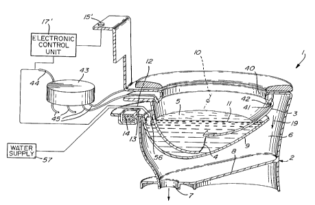
A first preferred embodiment of the toilet
in accordance with the present invention is
illustrated in Figure 1 and is generally identified by
the reference 1.
The toilet 1 comprises a frame 2. The
frame 2 is advantageously made of porcelain. However,
other materials such as plastics and fibreglass can be
contemplated.
The frame 2 includes a toilet bowl 3
formed with a waste water bottom discharge opening 4
W O 95123261 ~ ~ PCT/CA95/00121
oriented generally forwardly to discharge waste water
5 from the bowl 3 in a generally forward flow.
Under the toilet bowl 3, the frame 2
5 defines a hollow chamber 6. Hollow chamber 6
comprises a waste water bottom discharge hole 7
connectable to a conventional waste pipe (not shown).
As shown in Figure 1, the hollow chamber 6 defines a
bottom wall 8 sloping toward the discharge hole 7
10 whereby waste water discharged in the hollow chamber
6 falls on that bottom wall 8 and flows toward the
discharge hole 7 to be evacuated through the latter
hole 7 and the waste pipe (not shown) connected
thereto.
Interposed between the bowl 3 and the
hollow chamber 6 is a tilting cup 9 made from any
suitable material such as plastic, porcelain,
fibreglass, resinous material, metal, etc. More
specifically, the tilting cup 9 is pivotally mounted
on the frame 2 about a horizontal, transversal axis
10. It is to be understood that tilting cup 9 could
also be pivotally mounted on a support surface other
than frame 2. In the non-tilted position of Figure 1,
the cup 9 follows the general outline of the toilet
bowl 3 and therefore extends over the discharge
opening 4 of the toilet bowl 3. As the cup 9 is not
tilted, it is capable of containing water 5 which is
communicated to the toilet bowl through the bottom
discharge opening 4. Of course, the cup 9 is
sufficiently large to retain a required level 11 of
water 5 in the toilet bowl 3, level 11 being
W O 95/23261 ~ ~ ~ ~ 5 g ~ PCT/CA95/00121
11
sufficient to prevent escape of sewage gases in the
room in which the toilet is placed.
The tilting cup 9 comprises a rearwardly
extending tongue 12 formed with a top cavity 13 in
which a counterweight 14 is placed. The position of
the axis 10 and the mass of the counterweight 14 are
selected to enable the counterweight 14 to
counterbalance the mass of water 5 and maintain the
cup 9 in the non-tilted position of Figure 1.
To operate the toilet 1, the user rotates
a handle 15 to lift the rear free end 16 of the tongue
12 through a lever 17 and a chain 18. The cup 9 then
tilts in the direction of the arrow 19 until it
reaches a tilted position such as that shown in Figure
5. Then waste water 5 from the bowl 3 is then
discharged through the opening 4, and then is
discharged from the cup 9 to the hollow chamber 6 to
be finally evacuated through the discharge hole 7 and
the waste pipe (not shown) connected thereto (see
arrow 20 of Figure 5).
In the tilted position of the cup 9 (see
for example Figure 5) the counterweight 14 still
produces a lever force tending to return the tilted
cup 9 to its original non-tilted position of Figure 1.
However, return of the tilted cup 9 to its original
non-tilted position of Figure 1 is delayed by a given
period of time by means of a piston device 21.
As illustrated in Figure 2 of the appended
drawings, the piston device 21 comprises a cylinder 22
WO 95/23261 ~ ~ ~.. ; .~ PCT/CA95/00121
~2 ) B~l~F3
12
having a lower end wall 23 pivotally connected to the
frame 2 of the toilet 1 through a bracket 24 (see
mechanical link shown as a dashed line 25 in Figure
1) . A piston 26 is mounted slidable into the cylinder
22, imperviousness of the joint between the peripheral
edge surface of the piston 26 and the inner wall of
the cylinder 22 being ensured by a dynamic O-ring 27.
A piston rod 29 has one end secured centrally of the
face of the piston 26 opposite to the lower end 23 of
the cylinder 22 and a second end 36 pivotally
connected to the rear free end 16 of the tongue 12 of
the cup 9. The piston rod 29 passes through a hole 32
of the upper end wall 30 of the cylinder 22,
imperviousness of the joint between the piston rod 29
and the hole 32 being ensured by a dynamic O-ring 31.
As can be seen in Figure 2, the piston 26
divides the inner volume of the cylinder 22 into upper
33 and lower 34 chambers. A conduit 35 of larger
diameter enables easy transfer of the air from chamber
33 to chamber 34 so as not to impede tilting movement
of the cup 9 triggered by the action of the handle 15,
lever 17 and chain 18. A check valve 37 is mounted in
the conduit 35 to enable flow of air only from the
upper chamber 33 to the lower chamber 34. A conduit
38 of smaller diameter, provided with an adjustable
choker 39 also interconnects the upper 33 and lower 34
chambers of the cylinder 22.
As the tilted cup 9 is returned to its
original non-tilted position of Figure 1 by the lever
force produced by the counterweight 14, air is
transferred from the lower chamber 34 to the upper
WO 95/23261 ~ ~ ~ ~ J U PCT/CA95l00121
13
chamber 33 of the cylinder 22. This air transfer can
be carried out only through the conduit 38 of smaller
diameter. The resistance to air flow induced by the
combined action of the small diameter of the conduit
38 and the choker 39 slows down the pivotal movement
of the cup 9 to thereby retard pivotal movement, that
is return of that cup 9 to the non-tilted position of
Figure 1 by a given period of time adjustable through
adjustment of the choker 39. Of course, this period
of time must be sufficiently long to enable the waste
water 5 from the bowl 3 to be evacuated, and to enable
cleaning of the bowl 3 and cup 9.
Obviously, the piston device 21 may be
replaced by any other mechanism capable of fulfilling
the same function. Similarly, it is also to be
understood that the combination of handle 15, lever 17
and chain 18 may be easily replaced by other
triggering systems such as electrical, electronic or
pneumatic systems.
Referring back to Figure 1, the toilet
bowl 3 defines an upper hollow rim 40 defining a
bottom annular flange 41 situated inside the bowl 3.
Emerging from the flange 41 are peripherally
distributed nozzles 42 directed toward the inner wall
of the toilet bowl 3.
As the cup 9 is tilted from the position
of Figure 1 to a tilted position such as shown in
Figure 5, a sequential valve 43 (Figure 1) is supplied
with water through an inlet tube 44 to sequentially
supply the nozzles 42 with this water through outlet
WO 95/23261 218 41 ~ ~ . PCT/CA95100121
14
tubes 45. An example of sequential valve is
illustrated in Figure 3.
The sequential valve 43 of Figure 3
comprises a housing 46 and a cover 47 to close that
housing 46 and form a water-tight enclosure. The
water supplied to the sequential valve 43 through the
inlet tube 44 drives a water turbine 48. An inner
semicircular wall 49 of the housing 46 deviates the
flow of water entering the housing 46 through the
conduit 44 to efficiently drive the turbine 48.
Rotational movement of the turbine 48 is transmitted
to a toothed wheel 50 of smaller diameter in meshed
engagement with a toothed wheel 51 of larger diameter.
Rotational movement of the toothed wheel 51 is finally
transferred to a water distribution disk 52.
The water distribution disk 52 is applied
to the bottom face 53 of the housing 46. The water
distribution disk 52 is provided with one or more
pairs of diametrically opposite holes 54 while the
bottom face 53 of the housing 46 is provided with
several pairs of diametrically opposite holes 55 each
connected to a corresponding one of the outlet tubes
45. Upon rotation of the disk 52, the pair of holes
54 become successively and sequentially aligned with
each pair of diametrically opposite holes 55. The
nozzles 42 are therefore supplied with water from the
housing 46 by pairs and sequentially to produce
sequential jets of water whose function is to clean
the inner wall of the toilet bowl 3 and the inside of
the cup 9.
WO 95/23261 ~ 8 PCT/CA95I00121
It is to be understood that the placement
and number of holes 54 in distributing disk 52 and
holes 55 in housing 46 can be varied at will to obtain
any desired sequence and number of jets of water out
5 of nozzles 42. Of course, the water distributing disk
52 can be replaced by any other types of valves
capable of fulfilling the same function such as piano
keys.
10 Those of ordinary skill in the art will
appreciate that the orientation of the nozzles 42 is
selected to optimize cleaning of the inner walls of
the toilet bowl 3 and the inside of the cup 9. For
the same purpose, the nozzles 42 can be designed to
15 produce circular, oval and/or flat water jets. Also,
the toilet can be provided with stationary, moving,
translating, pivotal and/or rotating nozzles 42.
Of course, supply of water to the inlet
tube 44 can be controlled both electronically and/or
mechanically. As an example, a float valve 56 is
mounted in the cup 9 outside the bowl 3 and is
responsive to the level of water 5 falling below level
11 upon tilting of the cup 9 toward the position of
Figure 5, to supply water from a water supply 57 to
the inlet tube 44 of the sequential valve 43. In the
same manner, after the cup 9 has returned to the non-
tilted position of Figure 1, the float valve 56
detects reaching of the level 11 by the water 5 to
interrupt supply of water from the water supply 57 to
the inlet tube 44. Of course, it is within the scope
of the present invention to replace the float valve 56
by any electronic and/or mechanical devices capable of
WO 95/23261 ~ ~ ~ ~ ~ ~ ~ PCT/CA95/00121
16
performing the same water supply control operation.
Similarly, to compensate for excessive water level at
standby, a small hole can be provided in cup 9 at an
appropriate level to drain away excess water.
Operation of the toilet 1 of Figure 1
therefore involves the following steps:
(a) the handle 15 is manually turned to cause
tilting of the cup 9 from the position of
Figure 1 to a tilted position such as
that of Figure 5;
(b) waste water from the bowl 3 and the cup
9 is discharged in the hollow chamber 6
and then evacuated through the discharge
hole 7 and the waste pipe (not shown);
(c) lowering of the level of water 5 below
level 11 is detected by the float valve
56; the float valve 56 then supplies
water from the water supply 57 to the
sequential valve 43 through the inlet
tube 44;
(d) the sequential valve 43 supplies water to
the nozzles 42 in pairs and sequentially
through the outlet tubes 45 in order to
produce sequential j ets of water to clean
the inner wall of the toilet bowl 3 and
the cup 9;
WO 95/23261 ~ j ~ PCT/CA95/00121
17
(e) the tilted cup 9 is returned to the non-
tilted position of Figure 1 by the lever
force produced by the counterweight 14,
this pivotal movement being slowed down
by the action of the piston device 21;
(f) as the tilted cup 9 pivots about the axis
to return to the position of Figure 1;
the cup is gradually filled with water
10 from the nozzles 42; and
(g) when the cup 9 has returned to the
position of Figure 1 and the water from
the nozzles 42 has filled the cup 9 to
level 11, the float valve 56 is shut off
and the sequential valve 43 is no longer
supplied with water. The toilet 1 is
then ready to be operated again through
manual operation of the handle 15.
Referring now to Figure la, it is also
within the scope of the present invention to replace
the handle 15, lever 17 and chain 18 assembly with an
electrical triggering system. In such a system, the
stem 12 of cup 9 is appropriately weighted with
counterweight 14 to bias the position cup 9 in a first
non-tilted position. When the cup is sufficiently
filled with water and waste products (about '-, full),
the cup 9 will automatically begin to tilt because of
gravity as the weight of cup 9 and its content
overcomes the weight of counterweight 14.
Consequently, in such a system, handle 15, lever 17
WO 95!23261 2 ~ g PCT/CA95/00121
18
and chain 18 are replaced by a single push button
trigger 15' or optionally a remote control unit (not
shown) which activates an electronic control unit 17'
which in turn activates a valve to supply water from
a water supply 57 to the inlet tube 44 of the
sequential valve 43. Sequential jets of water are
then ejected inside the inner wall of the toilet bowl
3 and inside the cup 9 to gradually fill cup 9 to a '-,
full level so that it automatically tilts as described
above. When tilted, cup 9 will assume a second
position namely the tilted position shown in Figure 5.
Throughout this tilting movement of cup 9, nozzles 42
will continue to eject water on the inner surface of
bowl 3 and cup 9 to. Delay means such as the above
described piston device 21 can be provided to delay
the return of cup 9 to its non-tilted position. With
or without delay means, cup 9 will of course
automatically resume its first non-tilted position
because of counterweight 14. Electronic control unit
17~ is of course programmed to effect sequential and
timed spraying of nozzles 42 to effect a thorough
rinsing of bowl 3 and cup 9.
In an optional embodiment, electronic
control unit 17' can be programmed to repeat the above
described cycle, namely to once again fill cup 9 to
about '-, full this time with fresh rinse water to
thoroughly clean bowl 3 and cup 9 which will once
again tilt into the second position shown in Figure 5,
return to its original non-tilted position shown in
Figure la and be finally filled with water to a preset
level, as described in relation with Figure 1, to
prevent escape of sewage gases from drain hole 7.
E~2184158
19
This final step will place the toilet 1 in its standby
position.
A second preferred embodiment of the
toilet in accordance with the present invention,
generally identified by the reference 60, will now be
described with reference to Figures 4-8 of the
appended drawings.
It should be pointed out that the
corresponding elements of the first and second
preferred embodiments of the toilet according to the
invention are identified by the same reference
numerals.
Referring to Figure 4, the toilet 60
comprises a frame 2. The frame 2 is advantageously
made of porcelain. However, other materials such as
plastics and fibreglass can be contemplated.
The frame 2 includes a toilet bowl 3
formed with a waste water bottom discharge opening 4
oriented generally forwardly to discharge waste water
from the bowl 3 in a generally forward flow.
Under the toilet bowl 3, the frame 2
defines a hollow chamber 6. Hollow chamber 6
comprises a waste water bottom discharge hole 7
connectable to a conventional waste pipe (not shown).
As shown in Figure 4, the hollow chamber 6 defines a
bottom wall 8 sloping toward the discharge hole 7
whereby waste water discharged in the hollow chamber
6 falls on that bottom wall 8 and flows toward the
A
.. _,.._.
,. - , ~ f ~ ' . , r - '- - .. .. r .- : _ ~ r ~ _ ..:~y,~..
..:.,. , ~ ~ r rt ~ ,. . f _ ~. ~ ~
- , ~ f . . - . w n - . _ , r .
r r
~~ ~ ~~ , .f
discharge hole 7 to be evacuated through, the latter
hole 7 and the waste pipe (not shown) connected.
thereto.
5 Interposed between the bowl 3 and the
hollow chamber 6 is a tilting cup 9,~~
. . More specifically,
the tilting cup 9 is pivotally mounted on the frame 2
about a horizontal, transversal axis 61. In the non-
10 tilted position of Figure 4, the cup 9 follows the
general outline of the toilet bowl 3 and therefore
extends over the discharge opening 4 of the toilet
bowl 3. As the cup 9 is not tilted, it is capable of
containing water 5 which is communicated to the toilet
15 bowl 3 through the bottom discharge opening 4. Of
course, the cup 9 is sufficiently . large to retain a
level 62 of water 5 in the toilet bowl 3.
Referring to Figure'4 and 6, the tilting
20 cup 9 is formed with pair of symmetrical, lateral and
integral-water reservoirs of which only the left one
63 is illustrated. Reservoir 63 is supplied with'
water through a tube 64 shown in dashed line in Figure
4. Reservoir 63 also comprises a bottom orifice 65.
The preferred embodiment of Figure 4 uses
a spring-biased float-operated latch mechanism 66. In
this preferred embodiment, the tilting cup 9 comprises
no rearwardly extending tongue but a rear edge 67
Mechanism 66 comprises a V-shaped arm 68 pivotally
_ mounted on the rear edge 67 of the tilting cup 9: On
the end of the V-shaped arm 68 situated inside the cup
9 is mounted a float 69.' A latch 70 is formed on the
.. ,.~E~T
m..,..
._ r f . ~ _. , , , f
' ' ' r y , . r i r r~
. r ' . : r . ..
r _ - - ~ r
21 X41 ~g ....
21
other end of the V=shaped arm 68 situated~outside the
cup 9. ' Latch 70 engages a latch-engaging hook
element 71 formed integral with the frame 2 of the
toilet 60 to maintain the cup.9 in the position of
Figure 4. A spring element 72 normally applies the
latch 70 to the hook element 71.
As illustrated in Figure 4, the toilet
bowl 3 defines an upper hollow rim 40 defining a
bottom annular flange 41 situated inside the bowl 3.
Emerging from the flange 41 are the peripherally
distributed nozzles 42 directed toward the inner wall
of the toilet bowl 3 and supplied with water through
respective outlet tubes 73 of a control valve device
74.
As it will be explained in the following
description, operation of the toilet 60 is controlled
by a valve device 7 4,
To operate the toilet 60, the user has
only to depress a push-button 75 (Figure 4).
Referring now to Figures 7 and 8, the
control valve device 74 comprises a sawtoothed wheel
76 surrounded by a ring 77 generally rectangular. in
cross section. Pivotally mounted in an inner cavity
78 of the ring 77 is a spring-biased pawl 79. More
specifically, the pawl 79 has a proximate end
pivotally mounted about an axis generally parallel to
the axis 80 of rotation of the sawtoothed~wheel 76.
A spring 81 interposed between the bottom of the
cavity 78 and the pivotal pawl 79 urges the ~free
~'~~O'~O
' P
W O 95123261 ~ ~ ,~ PCT/CA95/00121
22
distal end 83 of this pawl 79 on the sawtooth such as
82 of the wheel 76.
The push-button 75 comprises a rod 84
passing through a top wall 89 of the frame 2 and
extending toward the control valve device 74. A
connecting rod 85 (Figure 8) has a first end 86
pivotally connected to the end of the rod 84 opposite
the push-button 75, and a second end 87 pivotally
connected to the outer peripheral edge face 88 of the
ring 77.
Upon depression of the push-button 75,
longitudinal movement of the rod 84 is transmitted
through the connecting rod 85 to rotate the ring 77
about the axis 80 in direction 90. Rotational
movement of the ring 77 is then transmitted to the
sawtoothed wheel 76 through the pawl 79 of which the
end 83 is engaging one sawtooth 82. Upon releasing
the push-button 75, this push-button returns to its
non-depressed position (by the action of, for example,
a spring (not shown)). The ring 77 then rotates in
the direction opposite to direction 90 and the spring-
biased pawl 79 slides on the sawtooth 82 to engage
another upstream tooth 82.
Rotational movement of the sawtoothed
wheel 76 caused by depression of the push-button 75,
is transmitted to another toothed wheel 91 through a
shaft 92. As illustrated in Figures 9a and 9b, wheel
91 comprises a peripheral, annular edge surface 94
divided into a smooth annular axial portion 95 and a
toothed annular axial portion 96. The smooth annular
v ', v ,
W O 95/23261 ~ ,~ a ~ ~ ' ~ PCT/CA95/00121
23
axial portion 95 defines a cam section 97 and a
semicircular section 121 (Figure 9a).
As shown in Figure 8, wheel 76 and ring
77 may be located outside a water-tight housing 93 of
the control valve device 74, while wheel 91 is
situated inside that housing 93.
Water is supplied to the control valve
device 74 from a water supply 98 through an inlet tube
99 (Figure 4), and then through a spring-biased valve
100 (see arrow 101 in Figure 7). Valve 100 comprises
a tubular member 102 defining a conical seat 103, and
a plug element 104 defining a conical surface 105
fitting into the conical seat 103 and applied to that
seat 103 by means of a spring 106. An O-ring 107
ensures imperviousness of the joint between the seat
103 and the conical surface 105. The plug element 104
comprises an integral slender extension 108 extending
inside the housing 93 and having a rounded free end
109 applied to and sliding on the smooth annular axial
portion 95 of the wheel 91.
Initially, the rounded free end 109 of the
extension 108 is in the position shown in Figure 9a,
that is in the corner 110 of the cam section 97.
Rotational movement of the wheel 91 in direction 111
(Figure 9a) imparted by depression of the push-button
75 causes sliding or the free end 109 on the cam
section 97 and axial movement of the extension 108
against the force produced by the spring 106. The
conical surface 105 then moves apart from the conical
seat 103 whereby water penetrates through the valve
WO 95/23261 ~ ~ a 415 ~3 PCTICA95l00121
24
100 and flows through a conduit 112 formed inside the
housing 93 to drive a turbine 113. The conduit 112
comprises a semicircular wall 114 to deviate the flow
of water so as to efficiently drive the turbine 113.
Rotational movement of the turbine 113 is
transmitted to a speed-reducing gear system 115
through a shaft 116. The gear system 115 is situated
in a water-tight compartment 117 of the housing 93
whereby no water reach the toothed wheels of that gear
system 115.
The speed-reducing gear system 115
comprises a toothed wheel 118 to which rotation is
imparted upon rotation of the turbine 113. The
toothed wheel 118 is mounted onto a shaft 119 rotating
therewith to drive a wheel rotating ratchet mechanism
120 engaging the teeth of the toothed annular axial
portion 96 of the wheel 91 to rotate this wheel 91 at
a given speed in direction 111. This type of ratchet
mechanism is well known to those of ordinary skill in
the art and accordingly will not be further described
herein.
Therefore, as the toothed wheel 118
rotates to drive the ratchet mechanism 120 and rotate
wheel 91 in direction 111, the rounded free end 109 of
the plug element 104 slides first on the cam section
97 of the smooth annular axial portion 95 of the
annular edge surface 94 of the wheel 91 to gradually
open the valve 100, and then on the semicircular
section 121 in which the valve 100 is fully open.
WO 95/23261 ~ ~ PCT/CA95/00121
In the meantime, the water from the
conduit 112 having driven the turbine 113 fills the
housing 93 and is supplied to a compartment 122 of
that housing 93 through a hole 123 of a partition wall
5 124 (see Figure 7).
Also, the speed-reducing gear system 115
comprises a toothed wheel 125 to which rotation is
imparted upon rotation of the turbine 113. The
10 toothed wheel 125 is mounted on a tubular shaft 126
rotating therewith and passing through a partition
wall 127 situated between compartments 117 and 122.
Rotational movement of the toothed wheel 125 is
transmitted, through the shaft 126, to a toothed wheel
15 128 of smaller diameter in meshed engagement with a
toothed wheel 129 of larger diameter, wheels 128 and
129 being both mounted in the compartment 122.
Rotational movement of the toothed wheel 129 is
finally transferred to a water distribution disk 130.
Referring to Figures 7 and 10, the water
distribution disk 130 is applied to a wall surface 131
of the compartment 122. The water distribution disk
130 is provided with a pair of diametrically opposite
holes 132 while the wall surface 131 of the
compartment 122 is provided with several pairs of
diametrically opposite holes 133 each connected to a
corresponding one of the outlet tubes 73 of the
control valve device 74. Upon rotation of the disk
130, the pair of holes 132 become successively and
sequentially aligned with each pair of diametrically
opposite holes 133. The nozzles 42 are therefore
supplied with water from the housing 93 by pairs and
WO 95/23261 L PCT/CA95/00121
26
sequentially to produce sequential jets of water whose
function is to clean the inner wall of the toilet bowl
3 and the inside of the cup 9.
The water-distributing disk 130 is further
provided with a semicircular oblong hole 134
associated with a hole 135 of the wall surface 131.
Hole 135 is connected to tube 64 (Figure 4) supplying
the water reservoir 63 on both side of the cup 9.
Therefore, rotational movement of the
wheel 91 in direction 111 (Figure 9a) imparted by
depression of the push-button 75 causes sliding or the
free end 109 on the cam section 97 and axial movement
of the extension 108 against the force produced by the
spring 106 to allow water to flow through the conduit
112 and drive the turbine 113. Rotational movement of
the turbine 113 is transmitted to the speed-reducing
gear system 115 to rotate the toothed wheel 125,
rotational movement of wheel 125 being transmitted to
the water distribution disk 130 to supply the nozzles
42 with water from the housing 93 by pairs and
sequentially to produce the sequential jets of water
that clean the bowl 3 and cup 9.
Water from the nozzles 42 raises the level
of water 5 in the toilet bowl 3 from an initial level
136 to level 62, level 136 being sufficient to prevent
escape of sewage gases in the room in which the toilet
is placed. In the meantime, when the oblong hole 134
of the water distributing disk 130 is aligned with the
hole 135 of the wall surface 131, water is supplied to
the two lateral reservoirs such as 63 through
WO 95123261 ~ ~ PCTlCA95/00121
27
associated tubes) such as 64. Tubes) 64 pass close
to the axis 61 and are flexible to prevent those
tubes) to impede tilting movement of the cup 9.
When water 5 has reached level 62, the
lateral reservoirs such as 63 are full of water.
Also, the float 69 is responsive to that level of
water to pivot the V-shaped arm 68 and thereby
disengage the latch 70 from the hook element 71. The
cup 9 then tilts in the direction of the arrow 137
(Figure 4) until it reaches the tilted position of
Figure 5. Then waste water 5 from the bowl 3 is
discharged through the opening 4, and then is
discharged from the cup 9 to the hollow chamber 6 to
be finally evacuated through the discharge hole 7 and
the waste pipe (not shown) connected thereto (see
arrow 20 of Figure 5).
In the meantime, the nozzles 42 continues
to be supplied with water to produce the sequential
jets of water, and water from the two reservoirs such
as 63 is gradually discharged through the
corresponding bottom orifice 65. As water discharges
from the reservoirs such as 63 through the bottom
orifices 65, the centre of gravity of the cup 9 and
its contents translates rearwardly whereby the cup 9
pivots slowly about the axis 61 toward the original
non-tilted position of Figure 4, until the spring-
biased latch 70 engages the hook element 71. This
action delays return of the cup 9 to the non-tilted
position by a predetermined period of time to enable
appropriate evacuation of the waste water and cleaning
of the bowl 3 and cup 9. The cup 9 may be structured
WO 95!23261 PCT/CA9~/00121
28
for obtaining this translation of the centre of
gravity. Alternatively, counterweights can be added
as required to obtain this operation.
During return of the cup 9 to the non-
tilted position of Figure 4 and after the cup 9 has
returned to the non-tilted position of Figure 4, the
jets of water from the nozzles 42 raise the level of
water in the cup 9 and toilet bowl 3. The speed of
rotation of the wheel 91 driven by the speed-reduced
toothed wheel 118, the shaft 119 and the ratchet
mechanism is adjusted in function of the pressure of
water from the supply 98 to fill the bowl 3 and cup 9
to level 136 of Figure 4. More specifically, when the
level of water 5 reaches level 136, the rounded free
end 109 of the extension 108 of the plug element 104
leaves the end 139 (Figure 9a) of the semicircular
section 121 of the smooth annular axial portion 95 of
the annular edge surface 94 of the toothed wheel 91 to
fall in corner 110. Then the O-ring 107 seals the
joint between the conical seat 103 and the conical
surface 105 whereby water is no longer supplied to the
housing 93 through the valve 100 to thereby stop
operation of the turbine 113 and therefore operation
of the toilet 60 until the push-button 75 is depressed
again to trigger the above described cycle of
operation of the toilet 60.
Figure 11 illustrates the waste water
bottom discharge hole 7 situated in front of the
hollow chamber 6 to facilitate evacuation of the waste
water from the bowl 3 and cup 9. A drawback of the
embodiment of Figure 11 is that it does not meet with
WO 95/23261 ~ ~ a ~, ~ ~ ~ PCT/CA95/00121
29
the construction standards presently in force.
However, it would be easy, in new buildings, to
displace the waste pipe (not shown) to receive the
front waste water bottom discharge hole 7 of Figure
11.
In Figure 12 , an alternative construction
for the cup 9 is illustrated. It comprises two cup
halves 167 and 168 both tilting as shown in dashed
line to discharge waste water. A drawback of this
alternative is that a water-tight seal 169 is required
between the two halves 167 and 168 to hold water in
the cup 9.
To facilitate manufacture and maintenance
of the non-flushing toilet in accordance with the
present invention, it can be made of three pieces as
illustrated in Figure 13:
- a frame 170 defining a hollow chamber
172 with a waste water discharge hole 171 connectable
to the waste pipe (not shown). and an upper rim 173;
- a toilet bowl 175 formed with a
peripheral flange 176 to be mounted on the upper rim
173 with a rubber gasket 177 in between the rim 173
and the flange 176; and
- a tilting cup 174 pivotally mounted on
the frame 179 or bowl 175.
WO 95/23261 ~ PCT/CA95/00121
Another aspect of the subject invention
is concerned with a toilet provided with automatic
distribution of seat-covering paper.
For that purpose a toilet 140 comprises,
as illustrated in Figure 14, a pivotal cover 141
having a bottom face 142 formed with a shallow annular
recess 143 therein to contain pre-shaped seat-covering
paper sheets. As it will be described in the
10 following description, the user has only, to place of
sheet of paper on the annular seat 145 of the toilet
140, to pivot the cover 141 in direction 144 to apply
the cover 141 to the seat 14 5 and the to return the
pivotal cover 141 to its normal rest position shown in
15 dashed line at 146.
According to a first preferred embodiment
as illustrated in Figure 15, a stack 156 of pre-shaped
seat-covering paper sheets such as 147 are mounted in
20 the shallow recess 143. Each paper sheet 147 has two
diametrically opposite flaps 148 and 149 retained in
the recess 143 by means of suitable pressure-applying
fastener members 150 and 151. The exposed face of
each paper sheet 147 is also provided with a plurality
25 of adhesive strips 152 of which the positions are
optimized in view of optimizing adhesion of such sheet
to the top surface 155 of the seat 145. The flap 148
can be easily separated from the paper sheet 147 by
tearing along a perforated line (tear line) 153. In
30 the same manner, the flap 149 can be easily separated
from the paper sheet 147 by tearing along a perforated
line 154.
W O 95/23261 2 ~ a ~. ~ ~ ~ PCT/CA95/00121
31
In operation, the pre-shaped paper sheet
147 already covering the top surface 155 of the toilet
seat 145 is first removed. To install a fresh pre-
shaped seat-covering paper sheet 147 from the stack
156, the user pivots the cover 141 in direction 144 to
apply the exposed surface of the paper sheet 147 to
the top surface 155 of the seat 145 so as to adhere
the strips 152 to this top surface 155. Then, the
pivotal cover 141 is pivoted in the direction opposite
l0 to arrow 144 in view of returning the cover 141 to its
normal rest position 146. When the cover 141 leaves
the seat 145, the strips 152 are adhered to the top
surface 155 of the seat 145 and produce a retention
force that causes tearing of the paper sheet 147 along
the perforated lines 153 and 154 to thereby leave the
paper sheet 147 on the seat 145, which paper sheet 147
is pre-shaped to fit on the convex top surface 155 of
that seat 145.
Of course, the surface of each paper sheet
147 applied to the adhesive strips 152 of the adjacent
next paper sheet 147 of the stack 156 is smooth and
treated to prevent as much as possible adhesion of the
strips 152 thereto.
Also, to better apply the exposed face of
a paper sheet 147 to the top surface 155 of the seat
145, flat spring members such as 157 can be interposed
between the bottom of the shallow recess 143 and the
stack 156 of paper sheets 147.
According to a second preferred embodiment
as illustrated in Figure 16, the shallow recess 143 is
WO 95/23261 ~ ~ PCT/CA9~/00121
32
horseshoe-shaped and a stack 158 of pre-shaped seat-
covering paper sheets such as 159 are mounted in the
shallow recess 143. The exposed face of each paper
sheet 159 is provided with a plurality of adhesive
strips 160 of which the positions are optimized in
view of optimizing adhesion of such sheet to the top
surface 155 of the seat 145. In the preferred
embodiment of Figure 16, the stack 158 of paper sheets
159 is held in the shallow recess 143 by means of
mechanically and/or electrically operated pivotal
flappers 161-164 in response to detection of pressure
by pressure sensitive sensors 165 and 166. The
pivotal flappers 161-164 can also be manually
operated.
In operation, the pre-shaped paper sheet
159 already covering the top surface 155 of the toilet
seat 145 is first removed. To install a fresh pre-
shaped seat-covering paper sheet 159 from the stack
158, the user pivots the cover 141 in direction 144 to
apply the exposed surface of the paper sheet 159 to
the top surface 155 of the seat 145 so as to adhere
thp strips 152 to this top surface 155. The sensors
165 and 166 then detect pressure to withdraw the
flappers 161-164. Thereafter the pivotal cover 141 is
pivoted in the direction opposite to arrow 144 in view
of returning the cover 141 to its normal rest position
146. When the cover 141 leaves the seat 145, the
strips 160 are adhered to the top surface 155 of the
seat 145 and the sensors 165 and 166 detect no
pressure to release the flappers 161-164 which are
then inserted in between the paper sheet 159 adhered
to the seat 145 and the next adjacent sheet 159 of the
W O 95/23261 21 ~ 4 ~ 5 ~ PCT/CA95/00121
33
stack 158. It is believed to be within the capacity
of one of ordinary skill in the art to design the
pressure-activated and mechanically and/or
electrically operated flappers 161-164 of which the
function and operation has been explained in the
foregoing description.
Of course, each paper sheet 159 is pre-
shaped to fit on the convex top surface 155 of the
seat 145, and the surface of each paper sheet 159
applied to the adhesive strips 160 of the adjacent
next paper sheet 159 of the stack 158 is smooth and
treated to prevent as much as possible adhesion of the
strips 160 thereto.
Of course, paper can be replaced by any
other suitable material in the fabrication of the
sheets 147 and 159.
To improve the users' comfort, electric
heating elements (not shown) can be provided in the
cover 141 to warm the paper sheets 147 or 159.
Referring now to Figure 14 , another aspect
of the subject invention is concerned with a toilet
provided with automatic seat disinfecting system
provided in the toilet seat cover 141 and/or toilet
basin ring 166 located immediately below toilet seat
145. In this embodiment, cover 141 and seat 145 are
similar to conventional design in their general shape
and capability of swivelling to a horizontal position
or a raised back position. The inside portion of
cover 141 can be provided with various cleaning and/or
WO 95/23261 ~ ~ ~ ~ PCT/CA95100121
34
disinfecting systems (not shown), for example, solid
or liquid cleaning agents, supersonic waves
generators, heat generators, infra-red or ultra-violet
light generating means, laser, air-current, freezing
agents, detergent appliers, wipers, layers of
chemicals or vinyl coatings which quickly harden into
removable sheets on seat 145, etc. Of course, the
cleaning/disinfection will take place when the seat
145 is place in contact with overlying cover 141.
In an optional embodiment, the
cleaning/disinfecting systems could be placed in basin
ring 166 or simply be a layer 167 placed between
toilet seat 145 and basin ring 166.
Referring now to Figure 17, seat 145 could
be mounted on the frame 2 of toilet 1 using a ball
joint 168 where the ball 169 is integral with seat
145. Of course other mountings such as rotary end
caps (not shown) with slot openings (not shown) for
easy detachment and side reversal of seat 145 are also
contemplated. However, the ball joint arrangement is
preferred. Seat 145 could therefore be reversible at
will by rotating seat 145 in ball joint 168. One side
of the reversible seat would always be
cleaned/disinfected and ready for use whenever it
would be held in contact with layer 167 or basin ring
166. A user need only reverse the seat 145 to get a
clean/disinfected surface.
Although the present invention has been
described hereinabove with reference to preferred
embodiments thereof, these embodiments can be modified
WO 95/23261 ~ ~ PCT/CA95100121
at will, within the scope of the appended claims,
without departing from the spirit and nature of the
subject invention.
5 For example, tilting operation of the cup
9 and/or maintaining cup 9 in a standby position can
be effected as follows:
- by a piston made of flexible rubber and
supplied with water (hydraulic force);
10 - by filling a reservoir of the cup 9
with water to translate the centre of
gravity of the cup 9 and contents thereof
and thereby cause tilting of that cup;
- by displacing a weight again to
15 translate the centre of gravity;
- by means of a magnet or magnets
(magnetic force);
- through a spring;
- by detecting the level of water in the
20 bowl and activating an electric motor;
- through a gear arrangement;
- through detection of the presence of a
user;
- by remote control, etc.
It is within the scope of the present
invention to use any manual, electric, electronic,
mechanical, automatic, magnetic, gravity triggering
for tilting the cup 9.
In the same manner, the valves 21, 43 and
74 can be triggered either manually, electrically,
WO 95/23261 ~ ~ ~ PCT/CA95100121
36
electronically, mechanically, automatically,
magnetically, remotely or by gravity.
The level of water in the bowl 3 can be
controlled by an independent valve situated inside or
outside the sequential valve 43 or control valve
device 74.
It is also within the scope of the present
invention to provide a portable toilet including the
concepts described in the foregoing description.
Furthermore, it is contemplated that the portable
toilet be provided with a foldable supply water
container and optionally a foldable waste product
container.