Note: Descriptions are shown in the official language in which they were submitted.
~184319
Collapsible Container
The present invention relates to collapsible
containers.
Containers which can collapse to a more compact
form when not in use are desirable for a number of
situations, such as delivery of retail goods. Containers
loaded with retail goods can be transported to the
r~tailer, emptied, collapsed and then returned in their
collapsed condition. This makes return transport easier
by minimising the volume to be transported.
The invention provides a collapsible container
comprising a base, at least one side wall which may move
to a stowed position when the container is not in use, an
intermediate member, hinge means connecting the interme-
diate member with a first one of the side wall and the
base, and attachment means operable to attach the inter-
mediate member to the second one of the side wall and the
base, the intermediate member and the said second one of
the side wall and the base being manufactured separately,
and subsequently assembled by means of the attachment
means.
Preferably the intermediate member extends along
substantially the whole length of the side wall. The
intermediate member may be located below the lower edge
of the side wall, in use.
- 2 _ 2184 319
The attachment means may comprise cooperating
formations such as cooperating projections and recesses.
There may be detent means, preferably snap-together
detent means, operable to retain the cooperating
formations together. The cooperating formations may be
brought together by movement of a first type, and
subsequently moved to a locked condition by movement of a
s~ond type~~ The first and second types of movement may
be movement in different, preferably perpendicular,
directions. The cooperating formations may comprise a
hook formation for introduction into a projection in a
first direction, movement in a second direction serving
to engage the hook with the walls of the recess, thereby
locking the projection and recess together. The
attachment means may be detachable. The attachment means
may incorporate resilience for retaining the attachment
means in the attached condition.
The hinge means may comprise a live hinge.
Preferably the hinge means connects the
intermediate member with the side wall, and the
attachment means attaches the intermediate member to the
base.
The base may have rectilinear shape and the
2 1 843 t 9
container may comprise four side walls as aforesaid, and
corresponding intermediate members connected and attached
as aforesaid. The walls may fold over the base when the
container is collapsed.
Preferably the container comprises stacking
formations able to interlock with corresponding
~ .
formations on a like container when the containers are in
the erect or collapsed condition, and are stacked one on
the other, the stacked containers being substantially
prevented from relative movement by the interlocking of
the stacking formations.
The invention also provides a collapsible container
comprising a base, side walls having an erect condition
and a collapsed condition, the container further
comprising stacking formations able to interlock with
corresponding formations on a like container when the
containers are in the erect or collapsed condition and
are stacked one on the other, the stacked containers
being substantially prevented from relative movement by
the interlocking of the stacking formations.
Preferably the side walls are connected to the base
by hinge means. The side walls preferably lie across the
base when in the collapsed condition.
2184319
-- 4
The stacking formations may comprise projections
and recesses. The stacking formations are preferably
arranged to prevent containers sliding one on the other
when stacked. The stacking formations may comprise
castellations along wall edges which are uppermost when
the container is in the erect condition and/or
castellations located along the lower face of the base
and/or recesses or depressions in the face and/or edges
of the walls, the recesses or depressions being exposed
from above when the container is in the collapsed
condition, to receive castellations formed on the base of
a like container.
Preferably the stacking formations allow containers
to be stacked as aforesaid in a plurality cf relative
orientations, preferably orientations at right angles to
each other.
The side walls may move to the collapsed condition
when the container is not in use and the container may
comprise an intermediate member, hinge means connecting
the intermediate member with one of the side wall and the
base, and attachment means operable to attach the
intermediate member to the other of the side wall and the
base, the intermediate member and the said other of the
side wall and the base being manufactured separately and
2 1 ~3 i 9
-- 5
subsequently assembled by means of the attachment means.
It will be apparent from the following description
that the features of the first aspect of the invention
set out above can be used along with the features of the
second aspect of the invention as set out above, in
various combinations.
_
Embodiments of the present invention will now be
described in more detail, by way of example only, and
with reference to the accompanying drawings, in which:
Fig. 1 is a schematic perspective view of two
containers according to the invention, being stacked in
their erect condition;
Fig. 2 is a more schematic exploded view of one of
the containers of Fig. 1;
Fig. 3 is a highly schematic perspective view of
the container of Fig. 2 in the partially collapsed
condition;
Fig. 4 is an exploded section along the line IV-IV
in Fig. 2;
2 1 843 1 9
-- 6
Fig. 5 shows the containers of Fig. 1 being stacked
in the collapsed condition; and
Fig. 6 is a schematic plan view of the stacking
pattern of the containers of Fig. 5.
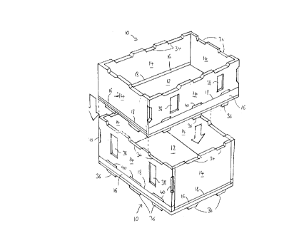
Referring to the figures, there is shown in Fig. 1
two collapslble containers 10 each comprising a base 12,
four side walls 14 which may fold to a stowed or
collapsed position (shown in Fig. 5) when the container
is not in use. Each side wall 14 is associated with an
intermediate member 16. Hinge means connect (in this
example) each intermediate member 16 with the
corresponding side wall 14. Attachment means (to be
described in relation to Fig. 2) attach the intermediate
members 16 to the base 12. The intermediate members 16
and the base are manufactured separately and subsequently
assembled by means of the attachment means to be
described.
In more detail, each container 10 has a generally
rectangular base 12 from which the four side walls 14
extend upwardly when the container is in the erect
condition, to form a generally parallelepipedal container
with an open top. In the example shown, which has a base
of approximately 600mm x 40ûmm, one pair of opposed side
21~431q
-- 7
walls is shorter than the other pair of opposed side
walls.
Each side wall is connected along its lower edge 18
to the corresponding intermediate member 16 which runs
along the whole length of the wall 14. The connection is
by means of a "live" hinge, that is, a thin web 19 (Fig.
4~ of materlal connecting the wall 14 and member 16 and
sufficiently thin to flex, allowing the wall 14 to hinge
relative to the member 16. Preferably, the various
components of the container are manufactured in a
plastics material, preferably by injection moulding. The
side wall and intermediate member can therefore be
manufactured as a single element having much reduced
thickness at the hinge 19.
When the container is in the erect condition, the
side walls 14 stand on the intermediate members 16.
However, the container 10 can be collapsed in the manner
indicated in Fig. 3. The two shorter walls 14 are first
folded toward each other to lie across the base 12. Fig.
3 shows the shorter walls fully folded to this stowed
position. It is to be noted that the height of the
intermediate members under the shorter walls is less than
the height of the intermediate members under the longer
walls so that in the position shown in Fig. 3, the upper
-- 2 1 843 1 q
-- 8
face of the shorter walls is at or below the line of the
hinges connecting the longer walls to their corresponding
intermediate members. This allows the longer walls to be
folded toward each other, down across the base and over
the shorter walls. The container is then in the
collapsed position shown in Fig. 5, which also shows
additional features to be described below.
The intermediate members 16 are attached to the
base 12 by a series of recesses 20 and projections 22
shown in Figs. 2 and 4. Each projection 22 is generally
L-shaped to form a hook having a short downwardly
extending limb 24 finishing at an elbow 26, from which a
generally horizontal and relatively long limb 28 extends
away parallel to the length of the member 16.
The recesses 20 are generally rectangular and
aligned parallel with the intermediate members 16. Their
length corresponds with the length of the limb 28. This
allows the members 16 to be lowered to introduce the
limbs 28 into the recesses 20, whereupon the members 16
can be slid sideways parallel to the length of the
members 16, to hook the long limbs 28 under corresponding
surfaces 30 (Fig. 4) within the recesses 20.
Alternatively, the second movement could be in a
different direction, such as twisting.
- 21 8431 9
There are preferably detent means associated with
the recesses and projections to hold them together once
connected. These may be permanent, but are preferably
releasable to allow an intermediate member 16 to be
removed by reversing the sequence of operations described
above. This allows an intermediate member 16 and the
corresponding side wall 14 to be removed and replaced,
for instance to repair damage.
Arrangements for holding the intermediate member 16
and base 12 together may be resilient as indicated in
Fig. 2, in which a small resilient upstand 32 projects
above the surface of the base 12, to be pushed down when
the intermediate member 16 is lowered into position. The
resilience of the upstand 32 causes it to push the
intermediate members 16 upwardly after connection to the
base, thereby increasing friction between the limbs 28
and surfaces 3û, to hold the intermediate member 16 in
position on the base 12.
Many other types of connection arrangement could be
used to securely connect the intermediate members 16 to
the oase 12. Other types of hinge could also be used.
In the example described above, it is preferred to
provide the hinge between the intermediate member 16 and
the side wall 14, with the attachments between the
2184319
- 10 -
members 16 and the base 12 being detachable. However, it
may in some circumstances be advantageous to provide the
hinge between the member 16 and the base 12, with the
members 16 and the corresponding walls 14 being attached
by an arrangement similar to that shown, or any of the
alternatives.
The containers shown in the drawings also
incorporate a number of features which assist stacking.
As has been described, the containers have a base 12 and
side walls 14 with an erect condition and a collapsed
condition. The container 10 further comprises stacking
formations 34,36,38 and 40. Firstly, the side walls 14
have top edges (when erect) which are castellated to form
notches 34. These overlie downward projections 36 from
the base 12 so that a container base can be stacked on a
container below when the lower container is in the erect
condition, by lowering the base of the upper container
until the base projections 36 on the upper container sit
in the notches 34 in the lower container. The notches 34
and projections 36 then engage to stop the upper
container sliding relative to the lower container. This
assists secure stacking. One arrangement uses
projections 36 which fit closely in corresponding notches
34. Alternatively, projections 36 could be shorter than
the notches 34, so that one notch 34 prevents sliding in
2 1 843 1 9
- 11 -
one direction, with another notch preventing sliding in
the opposite direction.
In the arrangements shown, the locations of the
notches 34 and projections 36 also allows containers to
be stacked when rotated through 9û~, there being three
notches 34 and projections 36 along each longer side of
the rectangwlar container, and two notches 34 and two
projections 36 along each shorter side. When stacked in
this way, the upper container will overhang the lower
container by approximately one third of its length.
Secure stacking in which relative sliding is
prevented can also be achieved when the lower container
is in the collapsed condition. This is illustrated in
Fig. 5. Two containers are shown there, both collapsed.
Depressions 38 formed in the face of the side walls 14
now face upwardly by virtue of the collapsed condition of
the containers. In addition, notches 40 around the edges
of the walls 14, including notches along the edge 18,
become exposed when the container is collapsed. The
arrangement and form of these depressions and notches
allows them to receive the projections 36 from a like
container stacked from above. The arrangement allows
stacking two containers in alignment, or at right angles
to one another (as shown). When stacked at right angles,
- 12 - 2 1 843 1 9
two projections 36 at the short side of the base 12 sit
in two notches 40 at the lower edge of a longer wall 14
of the lower container, leaving a third notch 40
unoccupied. Two projections 36 on the base of the upper
container sit in depressions 38, one in each of the
longer walls 14 of the lower container. Another two
projections 36 (obscured in Fig. 5) sit in notches at the
obscured end of the walls 14. A corresponding two
notches 40 at the visible end are unoccupled.
The spacing and sizes of the notches 34,
projections 36, depressions 38, and notches 40 locate the
upper container on the lower container to stop the
stacked containers sliding relative to each other.
The ability to stack collapsed containers at right
angles to one another facilitates the creation of a
stable stack as will now be described with reference to
Fig. 6. First, it should be noted that the depressions
38 are relatively wide, and allow two projections 36 to
be located in them, side-by-side, one from each of two
containers being stacked side-by-side on the same lower
container.
Turning to Fig. 6, a layer in a stack of collapsed
containers is formed by five containers arranged as
2~ 843~ 9
- 13 -
indicated by the solid lines. Three containers 50 have
their long sides adjacent and their short sides aligned.
Two more containers 52 are at right angles to the
containers 50 with shorter sides abutting and longer
sides adjacent the shorter sides of the containers 50.
Fig. 6 also indicates the arrangement on the layer
beneath, uslng broken lines. It can be seen that the
arrangementr~is the same except that the whole layer has
been rotated through a half turn. This results in every
container overlying at least two containers on the layer
below which, by virtue of the interconnecting notches,
projections and depressions, yields a secure stack akin
to the building of brickwork.
Containers of 600mm x 400mm base can be stacked in
the manner shown on a standard size pallet. Similar
overlapping stacking arrangements can be devised for
other container sizes, such as 400mm x 300mm, again with
similar advantages. The layout of the interlocking
formations for the erect and collapsed containers would
vary according to the size of container.
It will be apparent from the above description that
many variations and modifications can be made without
departing from the scope of the present invention. In
particular, many different sizes of container could be
2184319
- 14 -
designed, with corresponding arrangements of interlocking
formations. Other hinge techniques could be used, as
could alternative arrangements for attaching the
intermediate members to the base. Alternatively, the
intermediate member and the base could be hinged, with
the wall being made separately. The containers have been
described as being of plastics material, but other
materials could be used. Lock arrangements could be
incorporated to hold the container walls in the erect
position.
Whilst endeavouring in the foregoing specification
to draw attention to those features of the invention
believed to be of particular importance it should be
understood that the Applicant claims protection in
respect of any patentable feature or combination of
features hereinbefore referred to and/or shown in the
drawings whether or not particular emphasis has been
placed thereon.