Note: Descriptions are shown in the official language in which they were submitted.
1. ._.
w0 95127315 218 4 3 7 7 pCT~S94~03496
1
~pg~p~ METAL HYDR~E HYDft(~EN STORAGE ELECTRODES
Wchnic~l Field
This present invention relates to electrochemical hydrogen storage
alloys and rechargeable electrochemical cells using these alloys.
Background of the Invention
Rechargeable electrochemical cells that use a nickel-hydroxide
positive electrode and a metal hydride forming hydrogen storage
negative electrode are well known in the art. In fact over the past several
years, metal hydride cells have gained widespread market acceptance
due to the fact that they incorporate highly desirable performance
characteristics. Examples of these desirable characteristics include
high charge acceptance, relatively long-cycle life and operation over a
wide range of temperatures. Each of these performance characteristics
represent improvements over the nickel cadmium and other battery
systems known in the prior art.
Typically, the metal hydride hydrogen storage electrode is the
negative electrode in a hydrogen storage system. The negative electrode
material (M) is charged by the electrochemical absorption of hydrogen,
and the electrochemical evolution of a hydroxyl ion. The reaction which
takes place at the metal hydride electrode may be described according to
the following formula:
charge
M+H20+e- <-------------> M-H+OH-
discharge
The reaction that takes place at the posit'-~e electrode of a nickel
metal hydride cell is also a reversible reaction. In the case of a nickel
hydroxide electrode, the positive electrode reaction is as follows:
w0 95/27315 218 4 3 7 7 pCT/US94/03496
2
Ni(OH)2+OH- <-----------------> Ni00H+H20+e-
The negative electrode of most metal hydride electrochemical cells
can be characterized by one of two chemical formulas: The first is AB2,
which describes TiNi type battery systems such as described in, for
example, United States Patent No. 5,277,999. The second formula is AB5
which describes LaNiS type systems as described in, for example, U.S.
Patent No. 4,487,817.
Substantially all metal hydride electrochemical cells fall into one
of these two categories. However, with respect to both of these types of
materials, it has been found that the failure mode is usually the result of
degradation of the metal hydride electrode. This degradation has been
ascribed to the growth of a surface oxide film on the surface of the metal
hydride electrode. The oxide film reduces the active area of the electrode,
thus reducing the available area for the hydrogen reduction/oxidation
reaction to occur. Since the total current has to be distributed over a
smaller total area, the current density on the active surface increases.
As a consequence, the rate of formation of the irreversible oxide layer
increases. The internal resistance of the electrode also increases,
further hastening failure of the electrode.
Moreover, the power density of metal hydride cells is not as great
as in some other types of cells, notably nickel cadmium. Accordingly,
metal hydride cells have not been appropriate for several applications,
such as power tools.
Prior attempts to address these problems have focused mainly on
the addition of more and more modifier elements to the hydrogen storage
alloy material which makes up the metal hydride electrode. For
example, many current examples of metal hydride materials include ten
or more components mixed in varying ratios. As with any alloy, adding
new elements to the hydrogen storage material increases complexity of
the formation process, and adds to the cost of the overall material.
Accordingly, there exists a need to provide a means by which to .
reduce the formation of surface oxides on the surface of the metal
hydride electrode and in the metal hydride electrochemical cells. The -
means for reducing oxide formation should be relatively simple, and not
necessitate the use of additional elements added to the hydrogen storage
2184317
WO 95/27315 PCT/US94/03496
3
alloy. Further, a need exists for metal hydride cells having relatively
high power densities and capacities.
Summary of the Invention
Briefly, according to the invention, there is provided an electrode
for an electrochemical hydrogen storage cell. The hydrogen storage
electrode comprises a hydrogen storage alloy capable of reversibly
electrochemically storing and discharging hydrogen, and a layer of a
passivation material disposed atop said hydrogen storage alloy material.
In one preferred embodiment, the layer of passivation material may be
hydrogen permeable, and may further prevent or reduce the formation of
oxides on the surface of the hydrogen storage alloy material.
Further according to the invention, there is provided a method of
passivating a electrochemical hydrogen storage alloy material so as to
prevent the formation of oxides on the surface thereof. This method
includes the steps of providing a hydrogen storage alloy material capable
of electrochemically storing and discharging hydrogen, and disposing a
layer of a hydrogen permeable passivation material atop said hydrogen
storage alloy material.
Further according to the invention, there is provided
electrochemical hydrogen storage cells including a negative electrode, a
positive electrode, and an electrolyte. The negative electrode comprises a
hydrogen storage alloy capable of reversibly electrochemically storing
and discharging hydrogen and having a layer of hydrogen permeable
passivation material disposed there atop.
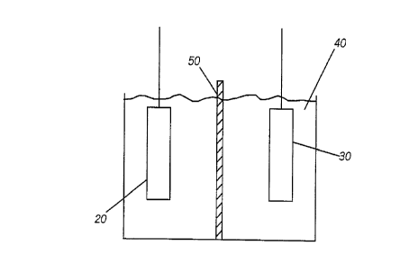
Brief Description of the Drawing:
FIG. 1 is a schematic representation of an electrochemical cell
including an improved metal hydride hydrogen storage alloy electrode in
accordance with the instant invention;
FIG. 2. is a schematic side view of a metal hydride hydrogen
storage alloy electrode coated with a layer of passivation material;
FIG. 3. is a chart illustrating voltage versus time for metal
hydride hydrogen storage electrodes including a layer of passivation
material versus unpassivated metal hydride electrodes and illustrating
electrode potential during charge;
WO 95/27315 2 PCT/US94/03496
4
FIG. 4. is a chart illustrating voltage versus time for passivated
and unpassivated metal hydride hydrogen storage electrodes showing
electrode potential during charge/discharge; and
FIG. 5 is a chart illustrating capacity versus cycle life with of '
electrodes in accordance with the instant invention versus unpassivated
electrodes.
Detailed Description of the Preferred Embodiment
While the specification concludes with claims defining the
features of the invention that are regarded as novel, it is believed that the
invention will be better understood from a consideration of the following
description in conjunction with the drawing figures, in which like
reference numerals are carried forward.
Referring now to FIG. 1, there is illustrated therein a schematic
representation of an electrochemical cell including a metal hydride
hydrogen storage alloy electrode coated with a layer of a passivation
material in accordance with the instant invention. The electrochemical
cell 10 includes a negative electrode 20 and a positive electrode 30. Both
electrodes are immersed in an electrolyte 40 and separated from one
another by an appropriate separator 50.
The negative electrode 20 of the electrochemical cell 10 is a metal
hydride hydrogen storage alloy electrode. Accordingly, the material may
be either the AB2 or AB5 type metal hydride hydrogen storage alloy
material. The metal hydride hydrogen storage alloy materials may be
characterized by the following formula: (Ti2_XZrXV4_yNiy) 1_z Mz
wherein M is a modifier element selected from the groups of materials,
including chromium, cobalt, manganese, aluminum, iron, iridium,
molybdenum and combinations thereof and where x, y, and z indicate
the relative proportion of each of the materials in the alloy. Disposed
atop the metal hydride hydrogen storage alloy material is a layer of
hydrogen permeable passivation material (as illustrated in more detail
in FIG. 2 hereof). '
The positive electrode 30 may be fabricated of any of the number of
known materials in the electrochemical arts. In one preferred
embodiment, a positive electrode may be a nickel hydroxide positive
electrode.
2184377
The negative and positive electrodes 20 and 30 respectively, are
immersed in electrolyte 40. The electrolyte may be an electrolyte known
in the art, such as, for example, 31% KOH. Disposed between the
negative and positive electrodes is a separator 50 fabricated of, for
5 example, a polymeric material, such as one or more layers of, or a
combination of non-woven or microporous polypropylene (Celgard*)
Referring now to FIG. 2, there is illustrated therein a cross
sectional side view of the negative electrode 20 of FIG. 1. The negative
electrode 20 includes a body of a metal hydride hydrogen storage alloy 22,
and a layer of a hydrogen permeable passivation material 25 disposed
atop the metal hydride hydrogen storage alloy material 22. As used
herein, a passivation material refers to a material which is a relatively
hydrogen-permeable material, and which discourages, reduces, or
prevents the formation of oxides, such as oxides of lanthanum and/or
nickel, on the surface of the metal hydride hydrogen storage alloy
material. The layer of passivation material serves several beneficial
purposes. For example, by preventing or reducing the formation of
oxides on the surface of the hydrogen storage alloy material, there is no
decrease in the active area of the electrode. In other words, the available
area for the hydrogen oxidation/reduction reaction remains unreduced.
Further, since there is no decrease in the total area of the electrode (since
no oxides are formed)over which current is distributed, the current
density at the surface is not increased. As a result, cycle life of the metal
hydride hydrogen storage alloy material may be considerably
lengthened.
It has also been found that the layer of passivation material
contributes to increased power density for the hydrogen storage alloy
material. This is due to the fact that hydrogen will react with, for
example, a palladium passivation material much more quickly than the
metal hydride material.
The electrochemical hydrogen storage alloy material may be
passivated so as to prevent the formation of oxides on the surface thereof
by providing a hydrogen storage alloy material capable of reversibly
electrochemically storing and discharging hydrogen, and disposing a
layer of hydrogen permeable passivation material atop the hydrogen
storage alloy material. Preferred materials for use as the passivation
material include palladium, cobalt, nickel, copper, gold, silver,
* trade-mark
2184377
-- WO 95/27315 PCT/US94/03496
6
platinum, iridium, vanadium, niobium, titanium, palladium alloys,
cobalt alloys, nickel alloys, copper alloys, gold alloys, silver alloys,
platinum alloys, iridium alloys, vanadium alloys, niobium alloys,
titanium alloys, and combinations thereof. Further, the passivation
material may be selected so that the reversible potential of the material is
not within the potential range of the positive and negative electrodes.
This will reduce the possibility of oxidation of the passivation material.
Accordingly, the passivation material may, in a preferred embodiment,
be palladium.
The passivation material may be disposed atop the layer of metal
hydride hydrogen storage alloy material in any one of the number of
known techniques. For example, the passivation material may be
deposited atop the hydrogen storage alloy by a vacuum deposition
method. Alternatively, the hydrogen storage alloy may be coated by the
passivation material in an electrodeposition process. In yet another
embodiment, the passivation material is mechanically sheared/mixed,
i.e., mechanically alloyed with said hydrogen storage alloy material so
as to coat it. An example of this process may be, for example, ball
milling. The passivation material is typically deposited atop the
hydrogen storage alloy material to a thickness of between 0.01 and 5.O~t,
and preferably approximately 0.5~t.
By providing a layer of passivation material on the surface of the
hydrogen storage alloy material, several improvements in the
performance of the alloy are observed. First, the passivation material
reduces the rate of growth of the irreversible oxide layers on the surface
of the metal hydride electrodes. This occurs since the passivation layer
acts essentially as a barrier between the metal hydride electrode and the
electrolyte. Thus, the majority of the hydrogen oxidation/reduction
occurs on the surface of the passivation material, rather than on the
surface of the metal hydride electrode. Thus, the cycle life of the
electrode is extended. Further, the passivation material, such as
palladium, is typically a good catalyst for the hydrogen
oxidation/reduction reaction. Thus, the passivation layer provides
reaction sites with less kinetic overpotential for hydrogen reactions. .
Accordingly, the electrode has less voltage loss, producing higher
working voltages and requiring lower charging voltage during
recharging cycles.
EN10086
. 2184371
7
Finally, a passivation material such as palladium is hydrogen
permeable. The hydrogen storing characteristics of the metal hydride
electrode is therefor not hindered in any way. During the charging of the
cell, hydrogen atoms diffuse through the palladium layer, entering the
body of metal hydride alloy and are stored therein. Thus, the capacity of
the cell will not be reduced.
EXAMPLES
An improved metal hydride hydrogen storage alloy material
including a layer of passivation material thereon was fabricated in
accordance with the instant invention. More particularly, metal hydride
hydrogen storage alloy material having the composition:
Lap,52Nd0,44Ce0.04Ni~.1~0.33~0.14Co0.1Fe0.41 and known as
International Battery Association Common Sample No. 3 was mixed
with a palladium powder. Combination of the materials was via
mechanical shearing/mixing. The mixing not only produced a
homogenous mixture of the two powders but by the shear force of the two
phases, the softer palladium was pressed against the harder, more
brittle metal hydride hydrogen storage alloy particles. As a result, the
palladium powder deformed and coated the metal hydride hydrogen
storage alloy particles. An example of mechanical shear/mixing is ball
milling. Experiments were carried out by grinding a 10% palladium
powder with the metal hydride hydrogen storage alloy powder in an
agate mortar prior to being fabricated onto teflon*-bonded electrodes. The
thickness of the palladium layer was about 0.5~.. The bonded, fixed
electrodes were then tested against the conventional metal hydride
hydrogen storage alloy electrodes described above, lacking the palladium
passivating layer. The results are illustrated in FIGS. 3-5.
Referring now to FIG. 3, there is illustrated therein the potential of
a palladium coated metal hydride electrode versus the potential of a
conventional nickel metal hydride electrode during constant current
charging at two different current levels. Specifically, lines 60 and 62
illustrate results for an electrode with and without a passivation
material, respectively. Testing for both electrodes was conducted at 50
mA. Similarly, lines 64 and 66 illustrate results for passivated and
unpassivated electrodes respectively, at 115 mA. From the curves
illustrated on FIG. 3, it is apparent that the electrode including the
* trade-mark
-.,
P~- w0 95127315
2 7 8 4 3 7 7 p~/pg94/03496
8
palladium coating not only exhibited less overpotential, (at least 100 m/V
improvement over conventional metal hydride electrodes) but also
required less voltage at the initial moment of the charging process.
Referring now to FIG. 4, there is illustrated therein a comparison
of the charge acceptance of a conventional nickel metal hydride electrode
versus that of a palladium coated metal hydride electrode. Both
electrodes were charged at C rate for 30 minutes and then discharged at
C/2 to measure the discharge capacity. Lines 70 and 72 illustrate
results, respectively, for electrodes with and without a layer of
passivation material, for tests conducted at 115 mA. Similarly, lines 74
and 76 illustrate results, respectively, for passivated and unpassivated
electrodes for tests run at a C/2 rate of 58 mA. The palladium coated
electrode demonstrated approximately 35% coulombic efficiency whereas
the conventional electrode demonstrated that only approximately 3% of
the charge was accepted. Accordingly, it may be appreciated that the
palladium coated electrode is considerably more efficient than
conventional metal hydride electrodes.
FIG. 5 illustrates life cycle testing for both passivated and
unpassivated metal hydride hydrogen storage electrodes. Specifically,
lines 80 and 82 illustrate voltage at end of discharge for passivated and
unpassivated electrodes respectively. Similarly, lines 84 and 86
illustrate, respectively, capacity for passivated and unpassivated
electrodes. As may be appreciated from FIG. 5, the voltage and capacity
performance characteristics of both electrodes was substantially the
same, except for cycle life, which was considerably longer for the
passivated electrode.
While the preferred embodiments of the invention have been
illustrated and described, it will be clear that the invention is not so
limited. Numerous modifications, changes, variations, substitutions and
equivalents will occur to those skilled in the art without departing from
the spirit and scope of the present invention as defined by the appended
claims.