Language selection

Search

Patent 2184457 Summary

Third-party information liability

Some of the information on this Web page has been provided by external sources. The Government of Canada is not responsible for the accuracy, reliability or currency of the information supplied by external sources. Users wishing to rely upon this information should consult directly with the source of the information. Content provided by external sources is not subject to official languages, privacy and accessibility requirements.

Claims and Abstract availability

Any discrepancies in the text and image of the Claims and Abstract are due to differing posting times. Text of the Claims and Abstract are posted:

  • At the time the application is open to public inspection;
  • At the time of issue of the patent (grant).
(12) Patent Application: (11) CA 2184457
(54) English Title: ZIPPER WITH ANTI-DERAILING RIBS
(54) French Title: GLISSIERE AVEC DISPOSITIF POUR EMPECHER LA SEPARATION INTEMPESTIVE DES BORDS DENTES
Status: Deemed Abandoned and Beyond the Period of Reinstatement - Pending Response to Notice of Disregarded Communication
Bibliographic Data
(51) International Patent Classification (IPC):
  • B65D 33/24 (2006.01)
  • A44B 19/26 (2006.01)
  • B65D 33/25 (2006.01)
(72) Inventors :
  • JAMES, PETER ANTHONY RICHARD (United Kingdom)
(73) Owners :
  • ILLINOIS TOOL WORKS INC.
(71) Applicants :
  • ILLINOIS TOOL WORKS INC. (United States of America)
(74) Agent: FINLAYSON & SINGLEHURST
(74) Associate agent:
(45) Issued:
(22) Filed Date: 1996-08-29
(41) Open to Public Inspection: 1997-03-02
Examination requested: 1996-08-29
Availability of licence: N/A
Dedicated to the Public: N/A
(25) Language of filing: English

Patent Cooperation Treaty (PCT): No

(30) Application Priority Data:
Application No. Country/Territory Date
08/522,696 (United States of America) 1995-09-01

Abstracts

English Abstract


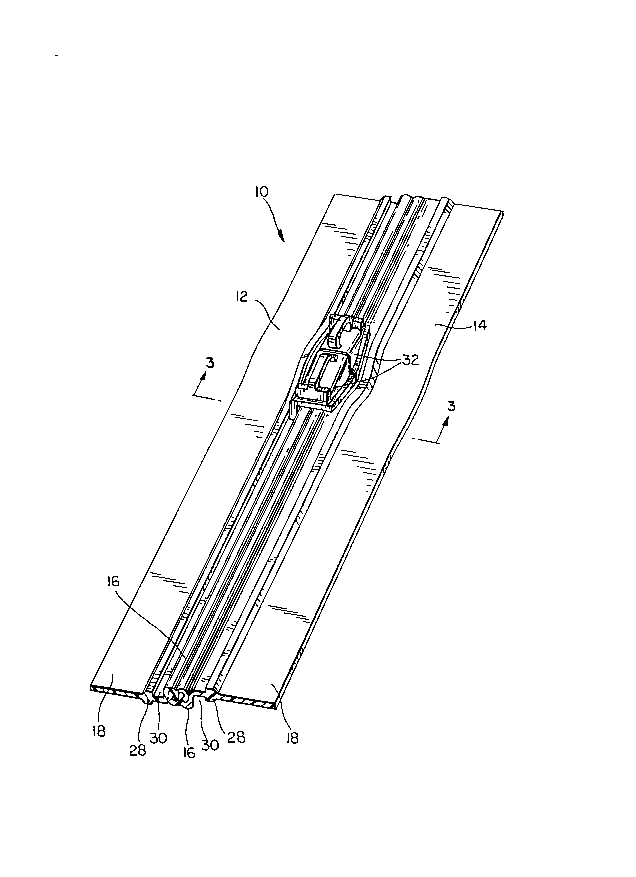
A resilient fastener or zipper, which may be
incorporated as part of a bag, pouch, wrapper or
liner, or which may be used as a protective garment
closure, includes a pair of flexible closure strips
and at least one zipper slider. The strips include
interlocking ribs and channels of complementary cross-
sectional shape which lock together in an interference
fit. The ribs have enlarged heads, and,
complementarily, the channels have enlarged bottoms.
The strips also include webs to which sheet material
or the like may be attached and, between the webs and
the interlocking ribs and channels, an anti-derailing
rib. The latter ensures that the zipper slider
remains on track and does not derail from the
interlocking ribs and channels when the slider is
moved therealong to open or to close the zipper.


Claims

Note: Claims are shown in the official language in which they were submitted.


The embodiments of the invention in which an exclusive property or
privilege is claimed are defined as follows:
1. A zipper comprising:
a first flexible closure strip and a second flexible closure
strip, each flexible closure strip having a web portion, said web
portions extending in opposite directions, an interlocking
portion, an anti-derailing rib between said web portion and said
interlocking portion and a guide channel for a zipper slider
between said anti-derailing rib and said interlocking portion,
said first and second flexible closure strips being extruded from
a polymeric resin material and said interlocking portions of said
first and second flexible closure strips being interlockable with
one another in a direction perpendicular to the web portions in an
interference fit.
2. A zipper as claimed in claim 1 wherein said anti-derailing
rib has a spade-shaped cross section.
3. A zipper as claimed in claim 1 wherein said polymeric resin
material has a hardness in the range of from 60 to 95 durometer.
4. A zipper as claimed in claim 1 wherein said polymeric resin
material is selected from a group consisting of low to medium
density polyethylene, polypropylene, polyurethane, polyester,
polyvinyl chloride, thermoplastic elastomers and thermoplastic
rubbers.
5. A zipper as claimed in claim 1 wherein said interlocking
portion of said first flexible closure strip is a male
interlocking member and said interlocking portion of said second
flexible closure strip is a female interlocking member.
6. A zipper as claimed in claim 1 wherein said
interlocking portion of said first flexible closure strip
includes at least one rib and at least one
6

channel, and said interlocking portion of said second
flexible closure strip includes at least one rib and
at least one channel which interlock with those of
said first flexible closure strip in an interference
fit.
7. A zipper as claimed in claim 6 wherein said at
least one rib of said interlocking portion of each of
said first and second flexible closure strips has an
undercut interlocking hook along a side thereof to
form an enlarged head, and wherein said at least one
channel of said interlocking portion of each of said
first and second flexible closure strips has an
undercut interlocking groove along a side thereof to
form an enlarged bottom to provide said interference
fit.
8. A zipper as claimed in claim 1 wherein said anti-
derailing rib is separated from said interlocking
portion on each of said first and second flexible
closure strips providing a track therebetween.
9. A zipper as claimed in claim 1 further comprising
at least one zipper slider for separating and for
joining said interlocking portions of said first and
second flexible closure strips, said at least one
zipper slider being between said anti-derailing ribs
of said first and second flexible closure strips.
10. A zipper as claimed in claim 9 wherein said
zipper slider is injection molded from a polymeric
resin material.
11. A zipper as claimed in claim 10 wherein said
polymeric resin material is polystyrene.
7

12. A zipper as claimed in claim 1 further comprising
at least one zipper slider for separating and for
joining said interlocking portions of said first and
second flexible closure strips, said at least one
zipper slider having a passage for said anti-derailing
ribs of said first and second flexible closure strips.
13. A zipper as claimed in claim 12 wherein said
zipper slider is injection molded from a polymeric
resin material.
14. A zipper as claimed in claim 13 wherein said
polymeric resin material is polystyrene.
8

Description

Note: Descriptions are shown in the official language in which they were submitted.


. ~ ~~ _ _
_ 3029-24
Zipper with Anti-Derailinct Ribs
Backctround of the Invention
1. Field of the Invention
The present invention relates to improvements in
resilient fasteners that provide flexible closures for
a variety of different uses, such as on bags, pouches,
wrappers, liners and protective garments. ~ More
specifically, the present invention relates to a new
and improved resilient fastener having a zipper slider
or sliders, wherein the closure strips of the
resilient fastener include anti-derailing ribs which
prevent the zipper slider or sliders from derailing
from the closure strips during the opening or closing
of the fastener.
2. Description of the Prior Art
Resilient fasteners, including those having
zipper sliders, are well-known in the art. Generally,
fasteners of this variety include a pair of flexible
closure strips, each extruded from a polymeric resin
material in continuous lengths and having an
interlocking rib and groove structure. . Such
structures on each of the pair of flexible closure
strips may be identical to one another, locking
together in an interference fit. Alternatively, one
of the pair of flexible closure strips may have a male
interlocking member, while the other of the pair may
have a female interlocking member into which the male
interlocking member may be snapped in an interference
fit.
Resilient fasteners of either of these two
varieties may be opened and closed with zipper
sliders, which track along the interlocking structures
of the flexible closure strips, joining them to one

CA 02184457 2001-02-15
another when pulled in one direction and separating them when
being pulled in the opposite direction.
The derailing of the zipper sliders from the interlocking
structures of the flexible closure strips, occasioned most often
by an overly energetic pulling action, is a significant problem of
the prior art in the present subject area. The present invention
provides a solution to this problem.
Summary of the Invention
Accordingly, the present invention is a resilient fastener or
zipper comprising a pair of flexible closure strips each having
both a web portion, to which sheet material or the like may be
attached and an interlocking portion. Between the web portion and
is the interlocking portion on each strip is an anti-derailing rib
and a guide channel for the zipper slider is between the anti-
derailing rib and the interlocking portion. The anti-derailing
rib prevents a zipper slider, provided for opening and closing the
zipper, from becoming untracked or derailed from the interlocking
portions under energetic or rough operating conditions. The anti-
derailing ribs may have a spade-shaped cross section. The
flexible closure strips are extruded from a polymeric resin
material.
The present invention will now be described in more complete
detail with frequent reference being made to the drawing figures
identified below.
Brief Description of the Drawings
Figure 1 is a cross section of the present resilient fastener
or zipper.
Figure 2 is a perspective view thereof.
Figure 3 is a cross section taken as indicated by line 3 - 3
in Figure 2.
2

~18~45 ~ - .
Figure 4 is a cross section, analogous to that
provided in Figure 3, of an alternate embodiment of
the present invention. .
Detailed Description of the Preferred Embodiment
In Figure 1, a pair of flexible closure strips,
joined to one another, of the present resilient
fastener or zipper is shown in cross section. The
zipper 10 comprises a first flexible closure strip 12
and a second flexible closure strip 14 which, as will
be noted, are identical to one another, so that
elements of one, described and labelled in the
paragraphs to follow, may be described in identical
terms, and are identically labelled in the figures.
The flexible closure strips 12, 14 each have an
interlocking portion 16 and a web portion 18. The
interlocking portions 16 have solid form-retaining
longitudinal ribs 20 and -longitudinal channels 22.
The ribs 20 have an undercut interlocking hook 24 on
one side thereof forming an enlarged head, while the
channels 22 have an undercut interlocking groove 26
forming an enl=arged bottom. The channels 22 are, in
fact, generally complementary to the ribs 20, so that
the flexible closure strips may lock together, as
shown in Figure 1, in an interference fit by the
engagement of hooks 24 with grooves 26.
The web portions 18 are provided to attach sheet
material, or the like, to each of the flexible closure
strips 12, 14. Between the web portion 18 and
interlocking portion 16 on each strip 12, l4 is an
anti-derailing rib 28, which may, as shown in Figure
1, be spade-shaped in cross section. The anti-
derailing rib 28 is somewhat separated from the
interlocking portion 16 to provide a track 30 on each
flexible closure strip 12, 14. As will be shown
3

y~g~~~~ ._
below, the tracks 30 guide the zipper slider or
sliders as they are being pulled along strips 12, 14,
being maintained thereon by anti-deraili.~g Yibs 28..
Figure 2 is a perspective view of the zipper 10
of the present invention comprising first and second
flexible closure strips 12, 14 and at least one zipper
slider 32. Two zipper sliders 32 disposed in back-to
back fashion may be provided as shown in Figure .2 such
that, when moved in a common direction along the
flexible closure strips 12, 14, one of the sliders 32
separates the interlocking portions 16 while the other
joins them.
Figure 3 is a cross-section taken as indicated by
line 3-3' in Figure 2 and illustrating the manner in
which anti-derailing ribs 28 carry out their intended
function. Zipper slider 32 is prevented from moving
laterally or transversely with respect to interlocking
portion 16 of flexible closure strips 12, 14 by the
-anti-derailing ribs 28 which abut against the lateral
edges thereof. A portion 34 of the slider 32 rides
within each of the tracks 30 separating interlocking
portions 16 from anti-derailing ribs 28 on flexible
closure strips 12, 14.
Figure 4 is a cross section, analogous to that
provided in Figure 3 of an alternate embodiment of the
present invention, zipper 40, wherein the anti
derailing ribs 28 act as an internal guide within
zipper slider 42, which includes passages 44 for the
ribs 28. The combined effect of portions 34 riding
within tracks 30 and ribs 28 passing through passages
44 as the slider 42 is moved along flexible closure
strips 12, 14 ensures against the slider 42 derailing
therefrom.
The flexible closure strips 12, 14 of the
resilient fasteners or zippers 10, 40 of the present
4

...
_ d
invention may be extruded from any polymeric material
having a hardness in the range from 60 to 95
durometer. Suitar~t. materials are low to medium
density polyethylene, polypropylene, polyurethane,
polyester, polyvinyl chloride as well as any of a
number of the other commercially applicable
thermoplastic elastomers and thermoplastic rubbers.
The zipper sliders 32, 42 may be injection molded from
any of the appropriate polymeric resin materials
commonly used to mold plastic parts, such as
polystyrene.
Modifications to the above would be obvious to
those of ordinary skill in the art, yet would not
bring the invention so modified beyond the scope of
the appended claims.
S

Representative Drawing
A single figure which represents the drawing illustrating the invention.
Administrative Status

2024-08-01:As part of the Next Generation Patents (NGP) transition, the Canadian Patents Database (CPD) now contains a more detailed Event History, which replicates the Event Log of our new back-office solution.

Please note that "Inactive:" events refers to events no longer in use in our new back-office solution.

For a clearer understanding of the status of the application/patent presented on this page, the site Disclaimer , as well as the definitions for Patent , Event History , Maintenance Fee  and Payment History  should be consulted.

Event History

Description Date
Inactive: IPC from MCD 2006-03-12
Application Not Reinstated by Deadline 2002-08-29
Time Limit for Reversal Expired 2002-08-29
Deemed Abandoned - Conditions for Grant Determined Not Compliant 2001-11-15
Deemed Abandoned - Failure to Respond to Maintenance Fee Notice 2001-08-29
Notice of Allowance is Issued 2001-05-15
Letter Sent 2001-05-15
Inactive: Approved for allowance (AFA) 2001-05-02
Amendment Received - Voluntary Amendment 2001-02-15
Inactive: S.30(2) Rules - Examiner requisition 2000-10-25
Inactive: Application prosecuted on TS as of Log entry date 1997-12-10
Inactive: Status info is complete as of Log entry date 1997-12-10
Application Published (Open to Public Inspection) 1997-03-02
Request for Examination Requirements Determined Compliant 1996-08-29
All Requirements for Examination Determined Compliant 1996-08-29

Abandonment History

Abandonment Date Reason Reinstatement Date
2001-11-15
2001-08-29

Maintenance Fee

The last payment was received on 2000-08-09

Note : If the full payment has not been received on or before the date indicated, a further fee may be required which may be one of the following

  • the reinstatement fee;
  • the late payment fee; or
  • additional fee to reverse deemed expiry.

Patent fees are adjusted on the 1st of January every year. The amounts above are the current amounts if received by December 31 of the current year.
Please refer to the CIPO Patent Fees web page to see all current fee amounts.

Fee History

Fee Type Anniversary Year Due Date Paid Date
Request for examination - standard 1996-08-29
MF (application, 2nd anniv.) - standard 02 1998-08-31 1998-08-19
MF (application, 3rd anniv.) - standard 03 1999-08-30 1999-08-05
MF (application, 4th anniv.) - standard 04 2000-08-29 2000-08-09
Owners on Record

Note: Records showing the ownership history in alphabetical order.

Current Owners on Record
ILLINOIS TOOL WORKS INC.
Past Owners on Record
PETER ANTHONY RICHARD JAMES
Past Owners that do not appear in the "Owners on Record" listing will appear in other documentation within the application.
Documents

To view selected files, please enter reCAPTCHA code :


To view images, click a link in the Document Description column. To download the documents, select one or more checkboxes in the first column and then click the "Download Selected in PDF format (Zip Archive)" or the "Download Selected as Single PDF" button.

List of published and non-published patent-specific documents on the CPD .

If you have any difficulty accessing content, you can call the Client Service Centre at 1-866-997-1936 or send them an e-mail at CIPO Client Service Centre.


Document
Description 
Date
(yyyy-mm-dd) 
Number of pages   Size of Image (KB) 
Description 2001-02-14 5 182
Claims 2001-02-14 3 93
Representative drawing 1997-11-25 1 27
Abstract 1996-12-08 1 23
Description 1996-12-08 5 177
Claims 1996-12-08 3 84
Drawings 1996-12-08 4 68
Reminder of maintenance fee due 1998-04-29 1 111
Commissioner's Notice - Application Found Allowable 2001-05-14 1 164
Courtesy - Abandonment Letter (Maintenance Fee) 2001-09-25 1 185
Courtesy - Abandonment Letter (NOA) 2002-01-23 1 172