Sélection de la langue

Search

Sommaire du brevet 2184457 

Énoncé de désistement de responsabilité concernant l'information provenant de tiers

Une partie des informations de ce site Web a été fournie par des sources externes. Le gouvernement du Canada n'assume aucune responsabilité concernant la précision, l'actualité ou la fiabilité des informations fournies par les sources externes. Les utilisateurs qui désirent employer cette information devraient consulter directement la source des informations. Le contenu fourni par les sources externes n'est pas assujetti aux exigences sur les langues officielles, la protection des renseignements personnels et l'accessibilité.

Disponibilité de l'Abrégé et des Revendications

L'apparition de différences dans le texte et l'image des Revendications et de l'Abrégé dépend du moment auquel le document est publié. Les textes des Revendications et de l'Abrégé sont affichés :

  • lorsque la demande peut être examinée par le public;
  • lorsque le brevet est émis (délivrance).
(12) Demande de brevet: (11) CA 2184457
(54) Titre français: GLISSIERE AVEC DISPOSITIF POUR EMPECHER LA SEPARATION INTEMPESTIVE DES BORDS DENTES
(54) Titre anglais: ZIPPER WITH ANTI-DERAILING RIBS
Statut: Réputée abandonnée et au-delà du délai pour le rétablissement - en attente de la réponse à l’avis de communication rejetée
Données bibliographiques
(51) Classification internationale des brevets (CIB):
  • B65D 33/24 (2006.01)
  • A44B 19/26 (2006.01)
  • B65D 33/25 (2006.01)
(72) Inventeurs :
  • JAMES, PETER ANTHONY RICHARD (Royaume-Uni)
(73) Titulaires :
  • ILLINOIS TOOL WORKS INC.
(71) Demandeurs :
  • ILLINOIS TOOL WORKS INC. (Etats-Unis d'Amérique)
(74) Agent: FINLAYSON & SINGLEHURST
(74) Co-agent:
(45) Délivré:
(22) Date de dépôt: 1996-08-29
(41) Mise à la disponibilité du public: 1997-03-02
Requête d'examen: 1996-08-29
Licence disponible: S.O.
Cédé au domaine public: S.O.
(25) Langue des documents déposés: Anglais

Traité de coopération en matière de brevets (PCT): Non

(30) Données de priorité de la demande:
Numéro de la demande Pays / territoire Date
08/522,696 (Etats-Unis d'Amérique) 1995-09-01

Abrégés

Abrégé anglais


A resilient fastener or zipper, which may be
incorporated as part of a bag, pouch, wrapper or
liner, or which may be used as a protective garment
closure, includes a pair of flexible closure strips
and at least one zipper slider. The strips include
interlocking ribs and channels of complementary cross-
sectional shape which lock together in an interference
fit. The ribs have enlarged heads, and,
complementarily, the channels have enlarged bottoms.
The strips also include webs to which sheet material
or the like may be attached and, between the webs and
the interlocking ribs and channels, an anti-derailing
rib. The latter ensures that the zipper slider
remains on track and does not derail from the
interlocking ribs and channels when the slider is
moved therealong to open or to close the zipper.

Revendications

Note : Les revendications sont présentées dans la langue officielle dans laquelle elles ont été soumises.


The embodiments of the invention in which an exclusive property or
privilege is claimed are defined as follows:
1. A zipper comprising:
a first flexible closure strip and a second flexible closure
strip, each flexible closure strip having a web portion, said web
portions extending in opposite directions, an interlocking
portion, an anti-derailing rib between said web portion and said
interlocking portion and a guide channel for a zipper slider
between said anti-derailing rib and said interlocking portion,
said first and second flexible closure strips being extruded from
a polymeric resin material and said interlocking portions of said
first and second flexible closure strips being interlockable with
one another in a direction perpendicular to the web portions in an
interference fit.
2. A zipper as claimed in claim 1 wherein said anti-derailing
rib has a spade-shaped cross section.
3. A zipper as claimed in claim 1 wherein said polymeric resin
material has a hardness in the range of from 60 to 95 durometer.
4. A zipper as claimed in claim 1 wherein said polymeric resin
material is selected from a group consisting of low to medium
density polyethylene, polypropylene, polyurethane, polyester,
polyvinyl chloride, thermoplastic elastomers and thermoplastic
rubbers.
5. A zipper as claimed in claim 1 wherein said interlocking
portion of said first flexible closure strip is a male
interlocking member and said interlocking portion of said second
flexible closure strip is a female interlocking member.
6. A zipper as claimed in claim 1 wherein said
interlocking portion of said first flexible closure strip
includes at least one rib and at least one
6

channel, and said interlocking portion of said second
flexible closure strip includes at least one rib and
at least one channel which interlock with those of
said first flexible closure strip in an interference
fit.
7. A zipper as claimed in claim 6 wherein said at
least one rib of said interlocking portion of each of
said first and second flexible closure strips has an
undercut interlocking hook along a side thereof to
form an enlarged head, and wherein said at least one
channel of said interlocking portion of each of said
first and second flexible closure strips has an
undercut interlocking groove along a side thereof to
form an enlarged bottom to provide said interference
fit.
8. A zipper as claimed in claim 1 wherein said anti-
derailing rib is separated from said interlocking
portion on each of said first and second flexible
closure strips providing a track therebetween.
9. A zipper as claimed in claim 1 further comprising
at least one zipper slider for separating and for
joining said interlocking portions of said first and
second flexible closure strips, said at least one
zipper slider being between said anti-derailing ribs
of said first and second flexible closure strips.
10. A zipper as claimed in claim 9 wherein said
zipper slider is injection molded from a polymeric
resin material.
11. A zipper as claimed in claim 10 wherein said
polymeric resin material is polystyrene.
7

12. A zipper as claimed in claim 1 further comprising
at least one zipper slider for separating and for
joining said interlocking portions of said first and
second flexible closure strips, said at least one
zipper slider having a passage for said anti-derailing
ribs of said first and second flexible closure strips.
13. A zipper as claimed in claim 12 wherein said
zipper slider is injection molded from a polymeric
resin material.
14. A zipper as claimed in claim 13 wherein said
polymeric resin material is polystyrene.
8

Description

Note : Les descriptions sont présentées dans la langue officielle dans laquelle elles ont été soumises.

. ~ ~~ _ _
_ 3029-24
Zipper with Anti-Derailinct Ribs
Backctround of the Invention
1. Field of the Invention
The present invention relates to improvements in
resilient fasteners that provide flexible closures for
a variety of different uses, such as on bags, pouches,
wrappers, liners and protective garments. ~ More
specifically, the present invention relates to a new
and improved resilient fastener having a zipper slider
or sliders, wherein the closure strips of the
resilient fastener include anti-derailing ribs which
prevent the zipper slider or sliders from derailing
from the closure strips during the opening or closing
of the fastener.
2. Description of the Prior Art
Resilient fasteners, including those having
zipper sliders, are well-known in the art. Generally,
fasteners of this variety include a pair of flexible
closure strips, each extruded from a polymeric resin
material in continuous lengths and having an
interlocking rib and groove structure. . Such
structures on each of the pair of flexible closure
strips may be identical to one another, locking
together in an interference fit. Alternatively, one
of the pair of flexible closure strips may have a male
interlocking member, while the other of the pair may
have a female interlocking member into which the male
interlocking member may be snapped in an interference
fit.
Resilient fasteners of either of these two
varieties may be opened and closed with zipper
sliders, which track along the interlocking structures
of the flexible closure strips, joining them to one

CA 02184457 2001-02-15
another when pulled in one direction and separating them when
being pulled in the opposite direction.
The derailing of the zipper sliders from the interlocking
structures of the flexible closure strips, occasioned most often
by an overly energetic pulling action, is a significant problem of
the prior art in the present subject area. The present invention
provides a solution to this problem.
Summary of the Invention
Accordingly, the present invention is a resilient fastener or
zipper comprising a pair of flexible closure strips each having
both a web portion, to which sheet material or the like may be
attached and an interlocking portion. Between the web portion and
is the interlocking portion on each strip is an anti-derailing rib
and a guide channel for the zipper slider is between the anti-
derailing rib and the interlocking portion. The anti-derailing
rib prevents a zipper slider, provided for opening and closing the
zipper, from becoming untracked or derailed from the interlocking
portions under energetic or rough operating conditions. The anti-
derailing ribs may have a spade-shaped cross section. The
flexible closure strips are extruded from a polymeric resin
material.
The present invention will now be described in more complete
detail with frequent reference being made to the drawing figures
identified below.
Brief Description of the Drawings
Figure 1 is a cross section of the present resilient fastener
or zipper.
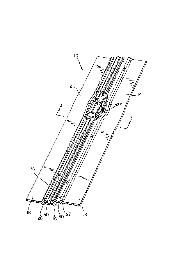
Figure 2 is a perspective view thereof.
Figure 3 is a cross section taken as indicated by line 3 - 3
in Figure 2.
2

~18~45 ~ - .
Figure 4 is a cross section, analogous to that
provided in Figure 3, of an alternate embodiment of
the present invention. .
Detailed Description of the Preferred Embodiment
In Figure 1, a pair of flexible closure strips,
joined to one another, of the present resilient
fastener or zipper is shown in cross section. The
zipper 10 comprises a first flexible closure strip 12
and a second flexible closure strip 14 which, as will
be noted, are identical to one another, so that
elements of one, described and labelled in the
paragraphs to follow, may be described in identical
terms, and are identically labelled in the figures.
The flexible closure strips 12, 14 each have an
interlocking portion 16 and a web portion 18. The
interlocking portions 16 have solid form-retaining
longitudinal ribs 20 and -longitudinal channels 22.
The ribs 20 have an undercut interlocking hook 24 on
one side thereof forming an enlarged head, while the
channels 22 have an undercut interlocking groove 26
forming an enl=arged bottom. The channels 22 are, in
fact, generally complementary to the ribs 20, so that
the flexible closure strips may lock together, as
shown in Figure 1, in an interference fit by the
engagement of hooks 24 with grooves 26.
The web portions 18 are provided to attach sheet
material, or the like, to each of the flexible closure
strips 12, 14. Between the web portion 18 and
interlocking portion 16 on each strip 12, l4 is an
anti-derailing rib 28, which may, as shown in Figure
1, be spade-shaped in cross section. The anti-
derailing rib 28 is somewhat separated from the
interlocking portion 16 to provide a track 30 on each
flexible closure strip 12, 14. As will be shown
3

y~g~~~~ ._
below, the tracks 30 guide the zipper slider or
sliders as they are being pulled along strips 12, 14,
being maintained thereon by anti-deraili.~g Yibs 28..
Figure 2 is a perspective view of the zipper 10
of the present invention comprising first and second
flexible closure strips 12, 14 and at least one zipper
slider 32. Two zipper sliders 32 disposed in back-to
back fashion may be provided as shown in Figure .2 such
that, when moved in a common direction along the
flexible closure strips 12, 14, one of the sliders 32
separates the interlocking portions 16 while the other
joins them.
Figure 3 is a cross-section taken as indicated by
line 3-3' in Figure 2 and illustrating the manner in
which anti-derailing ribs 28 carry out their intended
function. Zipper slider 32 is prevented from moving
laterally or transversely with respect to interlocking
portion 16 of flexible closure strips 12, 14 by the
-anti-derailing ribs 28 which abut against the lateral
edges thereof. A portion 34 of the slider 32 rides
within each of the tracks 30 separating interlocking
portions 16 from anti-derailing ribs 28 on flexible
closure strips 12, 14.
Figure 4 is a cross section, analogous to that
provided in Figure 3 of an alternate embodiment of the
present invention, zipper 40, wherein the anti
derailing ribs 28 act as an internal guide within
zipper slider 42, which includes passages 44 for the
ribs 28. The combined effect of portions 34 riding
within tracks 30 and ribs 28 passing through passages
44 as the slider 42 is moved along flexible closure
strips 12, 14 ensures against the slider 42 derailing
therefrom.
The flexible closure strips 12, 14 of the
resilient fasteners or zippers 10, 40 of the present
4

...
_ d
invention may be extruded from any polymeric material
having a hardness in the range from 60 to 95
durometer. Suitar~t. materials are low to medium
density polyethylene, polypropylene, polyurethane,
polyester, polyvinyl chloride as well as any of a
number of the other commercially applicable
thermoplastic elastomers and thermoplastic rubbers.
The zipper sliders 32, 42 may be injection molded from
any of the appropriate polymeric resin materials
commonly used to mold plastic parts, such as
polystyrene.
Modifications to the above would be obvious to
those of ordinary skill in the art, yet would not
bring the invention so modified beyond the scope of
the appended claims.
S

Dessin représentatif
Une figure unique qui représente un dessin illustrant l'invention.
États administratifs

2024-08-01 : Dans le cadre de la transition vers les Brevets de nouvelle génération (BNG), la base de données sur les brevets canadiens (BDBC) contient désormais un Historique d'événement plus détaillé, qui reproduit le Journal des événements de notre nouvelle solution interne.

Veuillez noter que les événements débutant par « Inactive : » se réfèrent à des événements qui ne sont plus utilisés dans notre nouvelle solution interne.

Pour une meilleure compréhension de l'état de la demande ou brevet qui figure sur cette page, la rubrique Mise en garde , et les descriptions de Brevet , Historique d'événement , Taxes périodiques et Historique des paiements devraient être consultées.

Historique d'événement

Description Date
Inactive : CIB de MCD 2006-03-12
Demande non rétablie avant l'échéance 2002-08-29
Le délai pour l'annulation est expiré 2002-08-29
Réputée abandonnée - les conditions pour l'octroi - jugée non conforme 2001-11-15
Réputée abandonnée - omission de répondre à un avis sur les taxes pour le maintien en état 2001-08-29
Un avis d'acceptation est envoyé 2001-05-15
Lettre envoyée 2001-05-15
Inactive : Approuvée aux fins d'acceptation (AFA) 2001-05-02
Modification reçue - modification volontaire 2001-02-15
Inactive : Dem. de l'examinateur par.30(2) Règles 2000-10-25
Inactive : Dem. traitée sur TS dès date d'ent. journal 1997-12-10
Inactive : Renseign. sur l'état - Complets dès date d'ent. journ. 1997-12-10
Demande publiée (accessible au public) 1997-03-02
Exigences pour une requête d'examen - jugée conforme 1996-08-29
Toutes les exigences pour l'examen - jugée conforme 1996-08-29

Historique d'abandonnement

Date d'abandonnement Raison Date de rétablissement
2001-11-15
2001-08-29

Taxes périodiques

Le dernier paiement a été reçu le 2000-08-09

Avis : Si le paiement en totalité n'a pas été reçu au plus tard à la date indiquée, une taxe supplémentaire peut être imposée, soit une des taxes suivantes :

  • taxe de rétablissement ;
  • taxe pour paiement en souffrance ; ou
  • taxe additionnelle pour le renversement d'une péremption réputée.

Les taxes sur les brevets sont ajustées au 1er janvier de chaque année. Les montants ci-dessus sont les montants actuels s'ils sont reçus au plus tard le 31 décembre de l'année en cours.
Veuillez vous référer à la page web des taxes sur les brevets de l'OPIC pour voir tous les montants actuels des taxes.

Historique des taxes

Type de taxes Anniversaire Échéance Date payée
Requête d'examen - générale 1996-08-29
TM (demande, 2e anniv.) - générale 02 1998-08-31 1998-08-19
TM (demande, 3e anniv.) - générale 03 1999-08-30 1999-08-05
TM (demande, 4e anniv.) - générale 04 2000-08-29 2000-08-09
Titulaires au dossier

Les titulaires actuels et antérieures au dossier sont affichés en ordre alphabétique.

Titulaires actuels au dossier
ILLINOIS TOOL WORKS INC.
Titulaires antérieures au dossier
PETER ANTHONY RICHARD JAMES
Les propriétaires antérieurs qui ne figurent pas dans la liste des « Propriétaires au dossier » apparaîtront dans d'autres documents au dossier.
Documents

Pour visionner les fichiers sélectionnés, entrer le code reCAPTCHA :


Pour visualiser une image, cliquer sur un lien dans la colonne description du document. Pour télécharger l'image (les images), cliquer l'une ou plusieurs cases à cocher dans la première colonne et ensuite cliquer sur le bouton "Télécharger sélection en format PDF (archive Zip)" ou le bouton "Télécharger sélection (en un fichier PDF fusionné)".

Liste des documents de brevet publiés et non publiés sur la BDBC .

Si vous avez des difficultés à accéder au contenu, veuillez communiquer avec le Centre de services à la clientèle au 1-866-997-1936, ou envoyer un courriel au Centre de service à la clientèle de l'OPIC.


Description du
Document 
Date
(aaaa-mm-jj) 
Nombre de pages   Taille de l'image (Ko) 
Description 2001-02-14 5 182
Revendications 2001-02-14 3 93
Dessin représentatif 1997-11-25 1 27
Abrégé 1996-12-08 1 23
Description 1996-12-08 5 177
Revendications 1996-12-08 3 84
Dessins 1996-12-08 4 68
Rappel de taxe de maintien due 1998-04-29 1 111
Avis du commissaire - Demande jugée acceptable 2001-05-14 1 164
Courtoisie - Lettre d'abandon (taxe de maintien en état) 2001-09-25 1 185
Courtoisie - Lettre d'abandon (AA) 2002-01-23 1 172