Note: Descriptions are shown in the official language in which they were submitted.
2
BACKGROUND OF THE INVENTION
1. FIELD OF THE INVENTION
The present invention relates to the control of fuel burning devices in
general and in particular relates to a fuel oil burner using a hot surface
ignitor
electrode that is sintered to full density with no porosity and which further
includes a control assembly that preheats the ignitor and then provides a
trial
ignition during which time the blower motor and the fuel oil are provided to
the combustion chamber. If a flame is not detected in less than one second,
the device is de-energized and starting must be retried.
DLMAINOl Doc: 186401 1
21~~~~2
3
2. DESCRIPTION OF RELATED ART
Portable forced air kerosene heaters typically comprise an outer housing
surrounding a combustion chamber. Air is forced into the combustion
chamber. A burner is located at one end of the combustion chamber and the
burner normally has a fuel nozzle frequently incorporating eductor means
providing jets of air to draw, mix, and atomize the fuel delivered by the
nozzle.
The nozzle, together with the eductors, discharges a combustible fuel-air
mixture into the combustion chamber. An ignitor is provided to ignite the
mixture and, after initial ignition, continuous burning occurs. Typically,
during
the continuous combustion, forced air heat currents issue from the end of the
heater opposite the burner and additional heat radiates from the surface of
the
heater housing.
Portable space heaters of the general type described are frequently-
provided with a direct spark type of ignitor and a motor. The motor normally
runs a fan supplying air to the combustion chamber and the eductors and
operates a fuel pump or air compressor to supply the fuel to the combustion
chamber.
When the portable space heater is functioning properly, fuel burning will
occur near the end of the combustion chamber at which the burner is located.
In the event of reduced air flow, however, the flame will move toward the
opposite end of the combustion chamber, the oxygen supply becoming
inadequate for proper combustion. Under such a circumstance, it is desirable
to shut down the heater. Inadequate air may result because of a malfunction
of the fan or a blocking of the passages for air into or out of the combustion
chamber.
DLMAIN01 Doc: 186401 1
218452
4
Inadequate operation and possibly dangerous conditions may also be
indicated by a lower than normal temperature of the burner flame,
representing improper combustion conditions.
It is also desirable to shut down the portable space heater when there is
a flame failure. This can occur by virtue of faulty ignition, a blockage of
the
fuel nozzle, or exhaustion of the fuel supply.
Further, many of the prior art portable, fuel oil fired, heaters utilize a
spark gap for ignition. (Some use heating coils that glow at a particular
temperature sufficiently hot to cause ignition of gaseous-type fuel.)
Hot surface ignition systems (HSI) have been used for more than twenty
years for gas ignition in units such as gas clothes dryers, gas ovens, gas
fired
furnaces, and boilers thus replacing and eliminating standing gas pilot
lights.
Low voltage ignitors ( 12 and 24 volts) of the hot surface type are made from
a patented ceramic/intermetallic material. These ignitors were used in
compact low wattage assemblies for gas fired ignition. The element reaches
ignition temperature in less than 3-5 seconds and utilizes about 40 watts of
power. The ignitor is made from a composite of strong oxidation resistant
ceramic and a refractory intermetallic. Thus hot surface ignitors have no
flame or spark. They simply heat to the required temperature for igniting a
fuel air mixture. Such ignitors have not been used in oil burning systems
because the ignitor material is porous and oil entering the porous cavities
causes buildup of the materials that are inimical to the operation of the
burner.
A 100 to 240V HSI ignitor has been developed in which the material is
compressed and sintered to full density leaving no porosity resulting in a
high
performance ceramic composite. It can operate at very high temperatures such
as 1,300 to 1,600°C. The application of such high voltage hot surface
ignition
device is especially attractive for use in the present invention wherein oil
fuel
DL!~IAINOl Doc: 186401 1
s
burning heaters are to be constructed. They provide unique advantages over
prior art gas flames, heating coils, and spark gap ignition systems.
In any case, malfunctions in the prior art heaters can cause insufficient
or incomplete burning or a failure to burn issuing fuel thus producing a
dangerous existence of highly flammable liquid or noxious fumes. Prior art
devices include a number of safety control circuits for fuel burning devices
proposed to avoid the many and often undesirable results of improper burning
or failure of flame in apparatus such as portable space heaters.
Thus, in U.S. Patent No. 3,713,766 a pretrial ignition period is
determined by a bimetallic thermal switch which, after a predetermined period
of time if ignition has not started, opens and removes the power. Manual
resetting of the bimetallic contacts is required to restart. However, during
burner operation, if the flame for any reason goes out, a new trial period is
automatically reinitiated. This could be dangerous if a fuel buildup in the
combustion chamber is ignited. Further, if the photocell detecting the flame
is shorted during operation, the burner will continue to operate because the
circuit cannot detect that the photocell has been shorted. In such case, the
unit thinks that there is a flame because, when there is a flame, the
photocell
resistance is very low, similar to a short. This control requires a dark
chamber
to start. However, this control does not lockout if start-up is negated
because of light in the chamber, undesirable results can occur. Thus in a case
where a cover was removed, the control can start the motor if a person comes
close enough to block the light. Further, spark ignition is constantly applied
during each cycle of the line voltage applied. Finally, there is an electric
spark
ignition circuit.
In U.S. Patent No. 3,651,327, a fluctuating control signal, due to flame
fluctuation, is rectified and energizes a control device that is a relay. This
circuit is entirely a DC circuit. It responds only to the presence or absence
of
,L'~
21~45~
6
a flame and would require a separate circuit for a trial ignition period. It
has
no start-up circuit or restart circuit, no preheat circuit and no hot surface
ignition.
In U.S. Patent No. 3,672,811, apparently a gas-type heater, if the
photocell shorts during operation, there is no detection of loss of flame.
Thus
there is no shutdown of the fuel flow or the air blower. It also uses spark
gap
ignition with a continuous spark being applied. There is no hot surface
ignition.
In U.S. Patent No. 3,741,709 there is no shutdown of the control system
if the photocell shorts during operation. There is no ignition preheat period,
no ignition trial period, constant ignition, and no hot surface ignition
device.
In U.S. Patent No. 3,393,039, if the unit fails to start during an ignition
period, a resistance heater opens the contacts of a thermal contact unit to
remove power. It utilizes only AC voltage, uses a mechanical relay to cause
continued operation of the circuit by detecting the heat of the flames and has
an automatic restart. It is not shutdown during operation if the flame is
gone.
It simply keeps trying to ignite. There is no hot surface ignition.
In U.S. Patent No. 3,537,804, an ignitor coil is used rather than a spark
gap or pilot flame. The temperature of the ignitor coil is sensed by a
photocell and, when the proper temperature is reached, the fuel valve is
opened. It has a trial ignition in which, if a flame does not occur, a heating
element opens bimetallic contacts to remove power. If the photocell is shorted
during operation, the system simply tries to restart and does not shut down
unless the bimetallic switch is opened after a heating element in the circuit
reaches a predetermined temperature.
DLMAINOl Doc: 186401 1
.. 21 ~45.~~
SUMMARY OF THE INVENTION
The present invention relates to a fuel oil type burner having a hot
surface ignitor element that is manufactured to full density with no porosity.
A blower provides air to the combustion chamber and an AC-to-DC converter
circuit converts AC power to a DC voltage output. A first control switch is
coupled between the AC power source and the hot surface ignitor electrode
for selectively providing the AC power to the hot surface ignitor electrode. A
second control switch is coupled between the AC power source and the blower
for selectively driving the blower. A flame detector is associated with the
combustion chamber for generating a signal if a flame is detected. A control
assembly is coupled to the DC output voltage and the flame detector for
starting and maintaining the fuel oil burning by initiating an ignitor preheat
period and an ignition trial period. The control assembly generates a first
signal to the first control switch to couple the ac voltage to the hot surface
ignitor to preheat the ignitor for a first predetermined period of time known
as the ignitor preheat time. It also provides heat for a second period of time
known as the trial ignition time period. It further generates a second signal
to the motor for introducing both air and fuel to the combustion chamber at
the beginning of the trial ignition period and for a very short period of time
immediately following the trial ignition period known as the flame test
period.
It de-energizes the fan blower motor, which removes the fuel to the burner, if
no ignition occurs during the flame test period.
A photocell acts as the flame detector and produces both an AC output
signal and a DC component output signal that is affected by ambient light.
The AC signal has a frequency depending upon the fluctuation of the flame.
A photocell flame control circuit includes a capacitor for receiving the
output
signal from the photocell. It blocks the DC voltage component generated by
DLMAINOl Doc: 186401 1
2184532
g
the photocell to prevent the fuel oil burner blower motor from being energized
by the DC signal because of ambient light. It includes a first drive circuit
coupled to a first time constant circuit and generates a first signal to
preheat
the ignitor for the first predetermined preheat time period. It continues to
heat the ignitor for the second predetermined trial ignition period of time. A
second time constant circuit is coupled to a second drive circuit for
energizing
the blower motor and providing the fuel oil and air substantially only during
the second ignition trial time period. A third time constant circuit is
coupled
between the photocell and the second drive circuit for maintaining the blower
in the energized state if a flame is detected by the photocell.
A flame sensing circuit in the control assembly receives the photocell AC
output peak-to-peak amplitude voltage to maintain the third time constant in
a charged state if the AC peak-to-peak amplitude and the flame frequency are
within predetermined limits. A transistor is biased to the ON condition to
prevent a charge from being maintained by the third time constant circuit. It
also has an OFF condition that provides a signal that will maintain a charge
on the third time constant circuit. If flame signals of amplitude and
frequency
from the photocell are within predetermined ranges, the transistor is turned
OFF with each alternate 1/2-cycle of the signal frequency thereby enabling a
charging voltage to be applied to the third time constant and maintain the
charge thereby maintaining the blower in the energized state. Thus the flame
sensing circuit that receives the signals from the photocell is frequency
sensitive. It is also amplitude sensitive. Therefore, if the flame frequency
is
within the predetermined range, the third time constant circuit remains
charged and when the flame frequency is lower than the predetermined limits
the third time constant circuit discharges thus allowing the blower motor to
be
de-energized. In like manner, when the flame amplitude is of insufficient
DLMAINOl Doc: 186401 1
2184532
9
magnitude to be within the predetermined limits, the third time constant
discharges and the blower motor is de-energized.
A lock-out circuit is coupled between the blower drive circuit and the
flame sensing circuit transistor to lock it in the ON position with a voltage
of
such magnitude that it cannot be overcome by any signal from the photocell.
This prevents any restart without first shutting off the AC voltage and
reapplying it so that the device has to recycle from the beginning.
Thus the present invention provides numerous advantages over the prior
art.
First, it uses a hot surface ignition ignitor that can ignite oil without
absorbing the oil and inhibiting the function of the hot surface ignitor.
Second, it has a very simple electronic circuit that has an ignitor preheat
time
period, an ignition trial period, and a subsequent flame test period in which,
if no flame is apparent, the system shuts down by removing not only the
voltage to the ignitor assembly, but also to the fan blower assembly that
stops
the air and fuel from being provided to the combustion chamber. The system
also locks out to prevent restart of motor due to photocell signal (in case
the
cover is removed while unit is still plugged in.) Further, it provides AC line
voltage to the ignitor that provides for wide use of the heaters in areas
where
alternating current power is available. It also allows the use of high voltage
AC to the ignitor and to the blower motor but low voltage DC to the control
circuits that can be formed of compact integrated circuits. Further it uses as
a flame detector a photocell which has both an AC level and frequency that
are detected to determine the establishment of a flame. A time constant
circuit is used to control the drive to the blower motor. If the amplitude and
frequency of the flame are both correct, the AC portion of the flame signal
will turn OFF a transistor each cycle. Each time the transistor is turned OFF,
a charging voltage is applied to the time constant circuit. This enables the
DLMAINOl Doc: 186401 1
?'18432
to
time constant circuit to be maintained in a charged state thus applying the
appropriate voltage to the drive circuit that is enabling the fan blower
motor.
If the frequency of the flame is correct but the amplitude is too low, even
though the transistor has the voltage applied to its base each cycle, the
voltage
will be of insufficient amplitude to turn the transistor OFF and thus will
allow
the time constant circuit to discharge. If the voltage level is sufficient but
the
frequency is too low, the transistor will be turned OFF but not for a
sufficient
period of time to recharge the time constant circuit thus allowing it to
discharge and stop the blower motor. The signal that stops the blower motor
is a high level logic signal which is also coupled back to the input of the
transistor base thus locking it in the ON position to hold the time constant
circuit in the discharged state. Thus the unit cannot be restarted without the
AC voltage being disconnected from the unit by turning a master switch OFF
and then reapplying the AC voltage thus preventing accidental restart.
Thus it is an object of the present invention to provide a fuel oil type
burner that utilizes a hot surface ignitor element associated with a
combustion
chamber, the ignitor element being sintered to full density with essentially
no
porosity.
It is another object of the present invention to provide a fuel oil type
burner that utilizes AC line voltage of 100 to 240 volts to drive both the
igrlitor
and the blower.motor and yet utilizes low voltage DC in its control circuits
to
control the application of that AC voltage to the ignitor and to the blower
motor.
It is yet another object of the present invention to utilize a transistor
that is biased to the ON state to cause essentially no voltage to be coupled
to
a time constant circuit which keeps the fan blower motor de-energized and
which has an AC coupled input such that when each negative input pulse of
sufficient magnitude from a flame detecting photocell is received, the
transistor
DLMAINOl Doc: 186401 1
2184~3~
11
is turned OFF and a voltage is applied to the time constant circuit to
maintain
it in a charged state and thus keep the fan motor energized when a proper
flame is detected.
It is still another object of the present invention to provide a lock-out
circuit which functions to bias the transistor to the ON state whenever flame
is lost thus preventing an automatic restart and requiring a manual restart of
the unit. However, it permits restart even if a flame exists in the chamber.
This allows safe, more controlled burning of any excess fuel collection.
Thus the present invention relates to a fuel oil type burner including a
fuel oil combustion chamber, a power source for providing AC line voltage, a
hot surface ignitor element associated with the combustion chamber, the
ignitor electrode being sintered to full density with essentially no porosity,
a
fan blower driven by a motor for providing fuel oil and air to the combustion
chamber, an AC-to-DC converter coupled to the AC power supply for
providing a DC voltage output, a first controllable switch coupled between the
AC power source and the hot surface ignitor, a second controllable switch
coupled between the AC power source and the fan blower motor, a flame
detector associated with the combustion chamber for generating an electrical
signal if a flame is detected, and a control assembly coupled to the DC output
voltage, the flame detector, and the first and second controllable switches
for
heating the hot surface ignitor with the AC voltage for a first predetermined
preheat period, energizing a blower motor and continuing to heat the hot
surface ignitor during a second predetermined trial ignition period,
energizing
the fan blower motor only at the beginning of the trial ignition period, and
for
a short flame test period immediately following the trial ignition. If a flame
appears but is insufficient to cause a photocell to produce an AC signal of
proper amplitude and frequency, or if the flame disappears, the unit is shut
down by removing fuel and air to the unit. After shutdown, the unit provides
DLMAINOl Doc: 186401 1
2184532
a lock-out mode that prevents accidental restart which makes the heater safer
for service personnel.
DLMAINOl Doc: 186401 1
21 X34532
13
BRIEF DESCRIPTION OF THE DRAWINGS
These and other more detailed objects of the present invention will be
more fully disclosed in the following DETAILED DESCRIPTION OF THE
PRESENT INVENTION in which like numerals represent like elements and
in which:
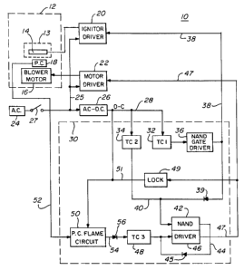
FIG. 1 is a schematic block diagram of the novel invention;
FIG. 2 is a corresponding circuit diagram of the invention; and
FIG. 3 is a schematic representation of a hot surface ignitor used
in the present invention.
DLMAINOl Doc: 186401 1
14
DETAILED DESCRIPTION OF THE PRESENT INVENTION
FIG. 1 is a schematic block diagram of the novel fuel oil type burner 10
illustrating the combustion housing 12 with the combustion chamber 13 shown
therein in phantom lines and at one of which is positioned a hot surface
ignitor
14 and, in close proximity thereto a flame sensor or photocell 18. In the
housing 12 is a blower motor 16, that not only provides the air for the
combustion chamber 12 but also provides the fuel oil. An ignitor driver 20 is
coupled to the hot surface ignitor 14 to selectively couple AC line voltage
from
source 24 on line 25 to the ignitor 14. The line voltage may be 110V or 220V
AC. In like manner, a motor driver switch 22 selectively couples the
alternating current voltage on line 25 to the blower motor 16 to provide the
fuel and air to the combustion chamber 12.
The AC voltage source 24 is also coupled through a switch 27 to a well-
known AC-to-DC converter 26 that generates a DC output voltage signal on
line 28. Typically, the DC voltage may be 12 volts on line 28. When 110V AC
line voltage is provided, R10 has a value of 2.7K ohms, SW. When 220V AC
line voltage is used, R10 has a value of S.SK ohms, 10W.
When the switch 27 is closed and the voltage from source 24 is applied
to the AC/DC converter 26, the DC voltage on line 28 commences charging
a first time constant circuit 32 and a second time constant circuit 34. For
example only, the first time constant 32 may be approximately 10 seconds. Its
output is coupled to NAND gate driver 36 whose logic low output on line 38
closes triac switch 20, the ignitor driver, and provides the AC line voltage
on
line 25 to the hot surface ignitor 14 to begin to heat it. Time constant TC1,
represented by block 32, has a time period that lasts for approximately 10
seconds. The first 5 seconds is a preheat period in which the ignitor 14 is
being brought to the proper temperature.
DLMAINOl Doc: 186401 1
15
At the same time the first time constant 32 begins to function, the second
time constant, TC2, represented by block 34, begins to function. Its time
constant period is approximately S seconds and is coupled on line 40 to NAND
gate 42. This causes no output on line 44 which includes diode 45 and is
coupled to the input of NAND driver 46 and a third time constant circuit,
TC3, represented by block 48. When the 5-second time constant has expired,
not only has the ignitor 14 reached proper temperature for an ignition trial,
but the output of the second time constant 34 on line 40 goes low to cause a
high output from NAND gate 42 on line 44 and through diode 45 to the third
time constant 48 and to the input of NAND driver 46. This causes a low
output from NAND driver 46 on line 47 to the motor driver circuit 22 to
enable it. Drive circuit 22 then couples the AC voltage on line 25 to the
blower motor 16 and it commences to provide fuel oil and air to the
combustion chamber 12.
The third time constant circuit, TC3, represented by block 48, has a very
short time constant period, for example from 0.6 to 0.95 seconds. If in that
time period, a flame test period, no flame is detected, the third time
constant
48 discharges causing a high output to be produced by NAND driver 46 on
line 47 which disables motor driver circuit 22 and removes the AC voltage 25
from the blower motor 16 thus stopping the operation of the system. In such
case, to attempt a restart, the switch 27 must be opened to initialize all
circuits
and then closed to attempt to restart.
If however a flame has been detected by photocell 18 and a proper signal
is present on line 52, photocell flame control circuit 50 will provide
intermittent pulses on line 54 through diode 56 to the third time constant
circuit 48 to maintain it in its charged state thus providing the proper
output
signal from NAND driver 46 on line 47 to cause switch 22 to maintain the AC
voltage applied to the blower motor 16.
DLMAINOl Doc: 186401 1
16
After the first time constant 32 expires, the output of NAND gate driver
36 on line 38 is coupled through diode 39 to the input of NAND gate driver
42 which causes a low output on line 44 through diode 45 to the third time
constant 48. If time constant circuit 48 has not received an input from the
photocell flame control circuit 50, it will discharge in less than 1 second
thus
removing power to the blower motor 16 as explained earlier.
Thus there are several advantages obtained over the prior art by using
the circuit of FIG. 1 as described. First, the use of a hot surface ignitor
with
oil burning systems is novel. They have been used with gas systems but not
with oil because of the reason of carbon formation that inhibits their use
after
a few cycles. Second, the use of AC line voltage being applied to both the
ignitor and the blower motor provides a versatility that has not been found
with prior art units. Third, the use of low voltage DC for the control
circuits
provides simplicity and economy in the construction of the control circuits
while allowing the high voltage alternating current to be used as the power
source for the ignitor and the blower motor. Fourth, the use of the three time
constant circuits is novel. The first time constant circuit preheats the hot
surface ignitor and, at the end of the preheat period, the second time
constant
circuit 34 turns ON the blower motor for providing fuel and air. At the end
of the ignition trial period, the first time constant generates an output
through
diode 39 and NAND gate 42 to cause the third time constant 48 to discharge
if a flame has not been detected. If the third time constant circuit 48
discharges within the less-than-one-second period, the output of driver 46 on
line 47 opens the switch 22 and removes the power to the blower motor 16.
This less-than-one-second discharge time of the third time constant 48 is
called
a flame test period.
Further, the photocell flame control circuit SO functions in a unique
manner as will be seen hereafter in relation to FIG. 2. Finally, to insure
that
DLMAINOl Doc: 186401 1
~a84~32
17
there is no buildup of fuel in the combustion chamber 12 when the "no flame"
condition is detected by the third time constant 48, the output signal from
driver 46 on line 47, that removes power to the blower motor, is also coupled
through a lock-out circuit 49 on line 51 to the photocell flame control
circuit
S 50 to disable it so that it cannot be used to provide a false signal to the
third
time constant to maintain the blower motor 16 and perhaps cause accidental
injury to service persons due to accidental restart of motor.
FIG. 2 discloses the details of the block diagrams of F1G. 1 and is a
complete circuit diagram of the present invention. As can be seen in FIG. l,
during power-up, when switch 27 is closed, the AC line voltage at 24 is
coupled
on line 25 to the ignition driver 20, the motor driver 22 and the AC-to-DC
converter 26. Twelve volts are produced by the AC-to-DC converter circuit
26 on line 28. As soon as the CMOS logic threshold is reached, the first time
constant circuit 32 and the second time constant circuit 34 begin to charge.
The junction of capacitor C6 and R9 in the first time constant circuit 32 is
coupled as an input to NAND gate 36. The other input is the 12 volts DC.
This causes the output on pin 10, line 38, to go essentially to ground
potential.
This ground potential on line 38 is coupled to an optical circuit 23 in the
ignitor driver circuit 20 causing a gate voltage to triac 21 and turning it
on.
This couples the AC line voltage to the ignitor 14 and begins the preheat
stage.
At the same time, the second time constant circuit 34 has developed a
decreasing voltage at the junction of CS and R6 on line 40. This voltage is
coupled as one input to the second NAND gate 42. Again, the other input is
the 12 volts DC. This causes a low output from NAND gate 42 on line 44
through diode 45 as an input to the third NAND gate 46 until the time
constant voltage decays to a level that turns ON gate 42. Because this is a
low
input to NAND gate 46, when the second time constant circuit 34 starts to
DLMAINOl Doc: 186401 1
2184532
18
decay, a high output is developed on line 47 and coupled to motor driver
circuit 22. A high output cannot enable the circuit since a ground is
required.
However, when the voltage from the second time constant has decreased to
the CMOS level of its logic threshold, NAND gate 42 produces a high output
on line 44 that is coupled to diode 45 as an input to third NAND gate 46.
This causes a low output on line 47 to the motor driver circuit 22. It
activates
the optical circuit 17 that provides a gate voltage to triac 15 that conducts
and
couples the AC line voltage to the fan motor and fuel and air are provided to
the combustion chamber.
At the same time that the high output from second NAND gate 42 is
energizing the third NAND gate 46 to start the fan blower motor, it is also
charging third time constant circuit 48 containing parallel capacitor C3 and
resistor R12. This time constant circuit is very fast and lasts for a time
period
from 0.6 to 0.95 seconds. The third time circuit 48 starts to discharge at-
essentially the same time that the first time constant circuit 32 expires.
When
it expires, a low signal is input to the first NAND gate 36 causing a high
output on line 38 which removes heat to the ignitor 14. It is also coupled
through diode 39 to line 40 to force NAND gate 42 to have a low on output
line 44 through diode 45 to the input of third NAND gate 46 as well as to
third time constant circuit 48. If no flame has been detected by that time,
the
third time constant circuit 48 discharges to a low voltage thus causing a high
on the output of third NAND gate 46 on line 47 to disable the driver gate 22
and remove the power to the blower motor 16. Thus the unit is disabled. At
the same time, the disabling output on line 47 from third NAND gate 46,
which is a high signal, is coupled through lock-up circuit 49 comprised of a
diode D5 and a resistor R13 to produce an output on line 51 that is coupled
to the base of the transistor Q1 in the photocell flame control circuit 50.
This
large signal turns transistor Ql ON and essentially grounds line 54 to the
z a ~~5~z
19
diode 56 thus ensuring that third time constant circuit 48 cannot be charged
through the transistor Q1 in the photocell flame control circuit 50. Thus the
circuit is effectively disabled and locked in that state.
To restart, switch 27 has to be opened, all of the circuits initialized and
the switch 27 reclosed to commence the restart process all over again.
If, during the flame test period immediately following the ignition trial
period, a flame is detected by photocell 18, the signal on line 52 is coupled
through capacitor C1 to the base of transistor Q1 in the photocell flame
control circuit S0. Since the photocell 18 produces an AC output voltage,
because of the flickering or fluctuating flames, if the peak-to-peak amplitude
of the output from the photocell 18 is sufficiently high, the negative going
pulses will be applied through capacitor Cl to the base of Q1 thus turning it
OFF. When it is turned OFF, the 12 volts DC signal on line 28 is coupled
through resistor R4 to the diode 56, charges capacitor C3, and thus the third
time constant circuit 48. Thus during every negative cycle of the waveform
being received from the photocell 18, typically a 30 hertz dominate frequency,
the transistor Q1 will be shut OFF to allow a DC voltage from a DC voltage
power supply on line 28 through R4 to be used to charge capacitor C3 that, it
will be recalled, is discharging rapidly. As long as the frequency period is
within a sufficient range to enable the capacitor C3 to be continuously
recharged faster than it is discharging on the positive cycle, the blower
motor
will remain on.
In addition, the DC component of the flame signal from photocell 18 on
line 52 is blocked by capacitor C1 so that ambient light cannot activate the
circuit. However, if the flame is so low that the peak-to-peak amplitude of
the
signal being passed through C1 is not sufficient to overcome the bias on the
base of Q1 and turn it OFF, then the capacitor C3, and the third time constant
48, will discharge and the unit will be turned OFF. Thus both frequency and
DLMAINOl Doc: 186401 1
284532
the peak-to-peak amplitude of the signal detected by the photocell and
coupled on line 52 to transistor Q1 must be within a predetermined range in
order for the circuit to continue to keep power to the blower motor.
Again, the first time constant 32 has a time constant period of
5 approximately 10 seconds. The second time constant circuit 34 has a time
constant period of approximately 5 seconds and the third time constant circuit
48 has a time constant period of approximately 0.6 to 0.95 seconds. In
addition, it can be seen in FIG. 2 that the output of the NAND gate 46 on line
47, when it is high and disables the blower motor circuit 22, is also coupled
10 through the lock-up circuit 49 and diode DS to bias the base of transistor
Ql
in the photocell flame control circuit 50 to prevent it from being turned ON
by any spurious signals. Thus the circuit is locked to prevent a restart
without
removal of the AC voltage through switch 27.
Thus in summary, on power-up the DC power supply voltage goes from
15 0 to 12 volts. As soon as the CMOS logic threshold is reached, the three
NAND gates 36, 42, and 46 are initialized. NAND gate 36 turns ON the triac
21 in the ignitor drive circuit 20 which delivers AC line voltage to the
ignitor
assembly 14. After approximately 4.5 to 5.5 seconds, the ignitor preheat time,
third NAND gate 46 turns ON triac 15 in the blower motor drive circuit 22
20 which delivers AC line voltage to the motor 16. The ignitor 14 remains
turned
ON for approximately 3.5 to 5 more seconds, the ignition trial time, prior to
being turned OFF by the dissipation of the first time constant circuit 32.
When the blower motor 16 is turned on, it delivers air to a siphon nozzle,
well
known in the art, which draws fuel oil up from a supply source while at the
same time the fan attached to the motor shaft forces secondary combustion air
into the combustion chamber assembly. During the ignition trial period, if all
systems are "go", the atomized fuel is lit by the ignitor 14 and a flame will
be
established in the chamber 12. The photocell 18 is positioned at the back of
DLMAINOl Doc: 186401 1
_ 218532
21
the chamber to monitor the flame in the chamber 12. If the photocell 18
senses an adequate amount of flame in the chamber, a multifrequency,
variable amplitude flame signal is fed into the photocell flame control
circuit
50 and the blower motor drive circuit 22 will remain turned on. If for some
reason an adequate flame in the chamber is not established, blower motor
driver circuit 22 will be turned OFF by NAND gate 46 within 1 second after
the ignition trial period has expired by reason of the third time constant 48.
After a "normal shutdown" due to an out-of-fuel condition, for example, the
control goes into a lock-out mode for safety considerations by the signal
through lock-out circuit 49 at which time the blower motor cannot be turned
ON unless power is removed and then reapplied through switch 27.
While the invention has been described in connection with a preferred
embodiment, it is not intended to limit the scope of the invention to the
particular form set forth, but, on the contrary, it is intended to cover such
alternatives, modifications, and equivalence as may be included within the
spirit and scope of the invention as defined by the appended claims.
DLMAINOl Doc: 186401 1