Note: Descriptions are shown in the official language in which they were submitted.
WO 95!24003 PCT/US95101901
- 1 -
INTERFACE APPARATUB FOR TWO-WIRE
COMMUNICATION IN PROCESS CONTROL LOOPS
This invention relates generally to a
process control system including a process
controller and process instruments and more
particularly to an interface apparatus for use in
such a system.
Background of the Invention
Process instruments such as current-to-
pressure transducers and valve positioners are
conventionally employed in industrial processes and
are controlled by a process controller which is
generally located remotely from and coupled to the
transducer or positioner by a two-wire link. The
process, controller provides a variable DC control
current signal of between 4 and 20 mA over the two-
wire link to the transducer or positioner or to any
other controllable device or, instrument. The
control current level changes the state of the
controllable device in proportion to the strength of
the variable DC current signal. For example, a
valve positioner might fully open a valve in
response to a 4 mA control current and fully close
the valve in response to a 20 mA control current.
In addition to being responsive to a
variable control signal, current-to-pressure
transducers and valve positioners have variable
parameters which may be adjusted to control the
operating characteristics of such devices.
Previously, these devices or process instruments
were adjusted manually when it was necessary to
WO 95124003 PCT/US95/01901
4 a
t:.
- 2 -
change the instrument parameters such as the zero
level, instrument range, output pressure, or valve
travel.
With the advent of so-called "smart"
devices capable of bidirectional communication, it
has become possible for the above-described
adjustments to be made automatically and from a
location remote from the device or field instrument.
Moreover, diagnostic testing and instrument
monitoring can also be conducted from a remote
location. However, means must then be provided for
transmitting a communication signal from a
communication site to the field instrument in order
to implement the adjustments and the field testing.
Because the process controller and the
communication site are often located a substantial
distance from the field instrument, undue effort and
expense is required to provide communication lines
independent from the two-wire control loop
interconnecting the communication site with the
field instrument. Accordingly, it is desirable to
transmit the communication signal over the two-wire
control loop together with the 4-20 mA control
signal so that additional wiring will not be
required. To that end, the modulated digital
communication signal is superimposed on the 4-20 mA
DC analog control signal used to control the field
instrument in order to allow serial communication of
data bit streams between the field instrument and
the communication site.
However, the presence of the modulated
digital communication signals, i.e., the AC
communication signals on the two-wire control loop
WO 95124003 PCT/US95l01901
- 3 -
can adversely affect the performance of the process
control system, and undesirable characteristics of
the process controller can adversely affect the AC
communication signals. For example, some process
controllers have an output impedance that is low
enough to attenuate the communication signal so that
the communication signal cannot be reliably detected
by the field instrument. As another example, some
process controllers output a 4-20 mA DC analog
control signal containing transients, noise, or
other undesired AC components that can interfere
with the modulated digital communication signals on
the two-wire control loop. As a third example,
during digital communication, the modulation of
voltage on the two-wire control loop can adversely
affect the output current of the process controller
or current readback circuits.
It is therefore desirable to couple an
interface apparatus between the process controller
and the ffield instrument. Such an interface
apparatus must be designed to regulate the analog
control signal to remove unwanted noise therefrom
and to effectively isolate the process controller
from the digital communication signal by providing
the interface apparatus with an output having a high
impedance to frequencies present in the digital
communication signal.
Several attempts to integrate such an
° interface apparatus into a process control loop have
proven unsuccessful. A passive RC circuit, for
' example, either has an output impedance that is too
low to allow modulation of the voltage by the
communication signal or has an input-to-output head
WO 95124003 PCT/US95/01901
~~.~~~I~ ~ k ~:
- 4 -
voltage that is too high to maintain el~,ctrical
compatibility between the process controller output
signal and the device. In limited circumstances, an
inductor could achieve some of the benefits of the
present invention, but, the inductor would have to
be prohibitively large and heavy in order to achieve
those benefits.
Summary of the Invention
In accordance with one aspect of the
present invention, a process control system includes
a process controller that develops a controller
output signal having at least a desired DC component
and an undesired AC component and a smart field
device having a digitally adjustable parameter. An
interface apparatus is coupled to the process
controller and to the device via a two-wire loop,
and means are provided for coupling a communication
signal onto the two-wire loop between the interface
apparatus and the device. The interface apparatus
of the present invention includes means for
substantially attenuating the undesired AC component
from the process controller and means electrically
coupled to the attenuating means for substantially
preventing the communication signal from
electrically affecting the process controller or
from being so attenuated as to be undetectable. The
device is responsive to the DC component of the
controller output signal, and the adjustable
parameter of the device is responsive to the
communication signal.
Where the process is operated in a
hazardous environment and it is necessary to provide
WO 95/24003 PCT/US95/01901
~l ~'4~I ~
- 5 -
an intrinsic°safety barrier in the process control
loop, the interface apparatus of the present
invention and the communication signal are
electrically compatible with the intrinsic safety
barrier.
In accordance with another aspect of the
present invention, an interface apparatus is
provided for coupling in a process control system
for permitting a communication signal to be coupled
to a two-wire loop interconnecting first and second
controller output terminals of a process controller
that develops a controller output signal at the
first and second controller output terminals
including at least a desired DC component and an
undesired AC component and first and second device
input terminals of a device responsive to the DC
component, wherein the device has an adjustable
parameter responsive to the communication signal.
The interface apparatus converts the controller
output signal into an interface output signal for
coupling to the device. The interface apparatus
includes means for substantially attenuating the
undesired AC component of the controller output
signal in the interface output signal and means
electrically coupled to the attenuating means for
substantially preventing the communication signal
from electrically affecting the process controller.
The interface apparatus is coupled between the first
and second controller output terminals and the first
and second device input terminals, and the
communication signal is coupled to the two-wire loop
between the interface apparatus and the device.
WO 95/24003 PCT/US95/01901
2184618
- 6 -
v..
The interface apparatus of~,tyhe present
invention enables reliable bidirectional
transmission of a communication signal to be
achieved between the field instrument and a
communication site remote from the field instrument
over the same two-wire loop on which the process
controller transmits control signals to the field
instrument. Accordingly, it is possible to provide
such bidirectional communication without the need
for costly and burdensome installation of additional
wiring. Moreover, the interface apparatus of the
present invention prevents the communication signal
from adversely affecting the performance of the
process controller and from being so attenuated as
to be undetectable and also attenuates noise
introduced onto the two-wire loop by the process
controller so that such noise cannot interfere
appreciably with the communication signal.
In the preferred embodiment of the
invention, the interface apparatus is an active
device powered, at least in part, by the controller
output signal and includes a capacitor coupled to
the process controller output. An adjustable
voltage reference circuit and a high-impedance
current source substantially prevent the
communication signal from electrically affecting the
process controller.
WO 95/24003 PCT/US95/01901
~1846I8
Brief Description of the Drapings
Those features of the present invention
which are believed to be novel are set forth with
particularity in the appended claims. The invention
may be best understood by reference to the following
description taken in conjunction with the
accompanying drawings in which like reference
numerals identify like elements in the several
figures and in which:
Fig. 1 is a block diagram illustrating a
process control system in accordance with the
present invention; and
Fig. 2 is a schematic diagram illustrating
a preferred embodiment of the interface apparatus
shown in Fig. 1.
Detailed Description
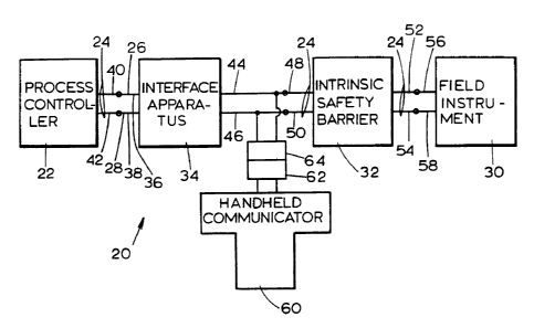
Referring initially to Fig. 1, a process
control system 20 includes a process controller 22
coupled to a two-wire control loop 24 including
first and second wires 26, 28. A highway-
addressable remote transducer (HART) field
instrument or device 30 such as a current-to-
pressure transducer or valve positioner is also
coupled to the control wires 26, 28.
An intrinsic safety barrier 32 may
optionally be coupled to the control wires 26, 28
between the process controller 22 and the device 30.
The intrinsic safety barrier 32 is an energy limiter
that substantially prevents electrical signals on
the control loop 24 between the barrier 32 and the
field instrument 30 from igniting combustible or
flammable materials present in the hazardous
WO 95124003 r PCT/US95/01901
_.
_ g _
environments in which the field ~rument 30 is
commonly used.
In accordance with the present invention,
an interface apparatus 34 is coupled to the control
loop 24 between the process controller 22 and the
field instrument 30. Specifically, the interface
apparatus 34 has first and second interface input
terminals 36, 38 which are coupled to first and
second controller output terminals 40, 42 of the
process controller 22. The interface apparatus 34
also includes first and second interface output
terminals 44, 46 which are coupled to first and
second barrier input terminals 48, 50 of the
intrinsic safety barrier 32.
The intrinsic safety barrier 32 includes
first and second barrier output terminals 52, 54
which, in turn, are coupled to first and second
device input terminals 56, 58 of the device 30. Of
course, if the optional intrinsic safety barrier 32
is omitted from the process control system 20, the
first and second interface output terminals 44, 46
are respectively coupled directly to the first and
second device input terminals 56, 58 of the device
30. While the intrinsic safety barrier 32 is a
conventional device which forms no part of the
present invention, the output produced by the
interface apparatus 34 of the present invention
enables the interface apparatus 34 to be used
compatibly with an intrinsic safety barrier 32 in
those applications where one is necessary.
Moreover, the intrinsic safety barrier 34, when
present, is also electrically compatible with the
communication signal (described below) which is
WO 95!24003 PCT/US95I01901
218618
- 9 -
coupled onto the first and second wires 26, 28 of
the two-wire control loop 24.
The device 30 is a so-called "smart"
device capable of receiving a communication signal
from an external source for setting parameters and
making adjustments to components of the device 30.
The device 30 is also capable of providing
information to the communication site to facilitate
diagnostic testing and interrogation of the device
30 by an operator of the process control system 20.
To provide for such communication, a hand-
held communicator 60 is coupled to the two-wire
control loop 24. As shown in Fig. 1, the
communicator 60 is coupled to the two-wire control
loop 24 near the output of the interface apparatus
34, but the communicator 60 can be coupled to the
two-wire control loop 24 a~ any convenient location
between the interface apparatus 34 and the field
instrument or device 30 (on either side of the
intrinsic safety barrier 32, if present). In
addition, the communicator 60 shown in Fig. 1
generally includes an optional two-wire input/output
connector 62 which is removably coupled with a
mating connector 64 which, in turn, is coupled to
the two-wire control loop 24. The removable
connector 62 is provided simply for convenience so
that the hand-held communicator 60 can be
disconnected from the control loop 24 and
reconnected as necessary. When stationary
communication equipment is used instead of the hand-
held communicator 60, the removable connector 62 and
the connector 64 will not be required if such
WO 95/24003 PCTIUS95/01901
~184~18
- 10 -
equipment can be permanently coupled to the"control
loop 24. :r.'.''~
The hand-held communicator 60,~~is operable
to provide communication signals to the device 30
via the two-wire control loop 24 in order to permit
a system operator to adjust parameters of the device
30 and interrogate the device 30 to check the status
thereof. While Fig. 1 depicts a hand-held
communicator 60, such as the Fisher-Rosemount Model
268 hand-held communicator, any suitable equipment
may be used to facilitate communication with the
device 30.
The communication signals conveyed to and
from the device 30 on the first and second control
loop wires 26, 28 are modulated digital
communication signals, i.e., AC communication
signals.modulated onto the variable DC control
signal provided by the interface apparatus 34 to the
device 30. These AC communication signals could
disrupt the operation of the process controller 22
in the absence of the interface apparatus 34.
Moreover, the process controller 22 could produce
distortion in the variable DC component of the
control signal, and this distortion could interfere
with the communication signal when present on the
control loop 24.
For the foregoing reasons, the interface
apparatus 34 is coupled between the process
controller 22 and the device 30. The interface
apparatus 34 is preferably an active device which is
powered, at least in part, by the controller output
signal. Moreover, the interface apparatus 34 has a
high-impedance output which prevents the
WO 95/24003 PCT/US95/01901
2~84~18
- 11 -
communication signal from interfering with the
process controller 22 and ensures that the
communication signal is not so attenuated by the
interface apparatus 34 as to be undetectable by the
device 30. The interface apparatus 34 also filters
the controller output signal to prevent noise,
transients, or other undesired AC components
produced by the process controller 22 from
interfering with the communication signal when
present on the control loop 24.
Referring now to Fig. 2, the structure and
operation of the interface apparatus 34 is described
in more detail. The interface apparatus 34 includes
a capacitor 66 connected across the control loop
wires 26, 28 for filtering the controller output
signal developed by the process controller 22 and
for storing energy therein. The interface apparatus
34 also includes a current drive stage 68. The
current drive stage 68 delivers a high-impedance
output current to the interface output terminals 44,
46 as a function of the voltage across the capacitor
66. In the interface apparatus 34 shown in Fig. 2,
the high-impedance characteristic of the current
output is provided by the open-drain configuration
of the enhancement-mode p-channel field-effect
transistor 70. An electrical network 72 including
an adjustable voltage reference 74, such as National
Semiconductor Company's LM285, is provided to
produce appropriate biasing of the transistor 70.
The electrical network 72 includes a transistor 76
that provides a voltage offset to maintain the
adjustable voltage reference 74 within its operating
limits as the input voltage to the interface
WO 95124003 PCT/US95/01901
2184618
A v
- 12 -
apparatus 34 is adjusted. It should be noted that~:~
the high-impedance output current may be.developed
by any suitable means and that the enhanceme~n~-mode
p-channel transistor is described herein simply as
an example.
In operation, upon the initial application
of current from the controller 22, the capacitor 66
begins to charge. When the capacitor 66 is charged
beyond the set voltage of the transistor 70, an
output current appears at the high-impedance output
terminals 44, 46 of the interface apparatus 34.
The desired output current can only flow
from the interface apparatus 34 when a first
potential difference between the first and second
interface output terminals 44, 46 is lower than a
second potential difference between the first and
second interface input terminals 36, 38. This
required input-to-output voltage difference, termed
the "voltage drop," must be small enough to ensure
that the DC component of the controller output
signal, which is coupled by the interface apparatus
34 to the device 30, is electrically compatible with
the device 30. Of course, if the voltage drop
produced by the interface apparatus 34 is too high,
the device 30 will not be controlled properly by the
process controller 22. The interface apparatus 34
as shown in Fig. 2 generally will require a voltage
drop of at least two volts for proper operation, but
the voltage drop must nonetheless be small enough to
ensure compatibility between the controller 22 and
the device 30. The actual output voltage of the
interface will be determined by the output current
and the load impedance. Also, in this embodiment,
WO 95/24003 PCT/LJS95I01901
zls4sls
- 13 -
wherein the interface apparatus 34 is powered solely
by the control signal, the interface apparatus 34
draws an operating current of approximately forty to
sixty microamps from the loop.
A diode 78 is connected between the first
and second interface input terminals 36, 38 of the
interface apparatus 34 to protect the interface
apparatus 34 from damage that may result if the
interface apparatus 34 is coupled to the process
controller 22 with the incorrect polarity.
Similarly, a diode 80 is connected between the first
and second interface output terminals 44, 46 of the
interface apparatus 34 to prevent damage that may
result from static discharge or from the interface
apparatus 34 being improperly installed in the loop.
As shown in Fig. 2, the connector 64, for
example, a 2-conductor AMP "Mini Universal Mate-N-
Lock" connector, is coupled to the first and second
interface output terminals 44, 46. The connector 64
is intended for use with a hand-held communicator,
such as the Fisher-Rosemount Model 268, or with a
HART-compatible multiplexing device, either of which
must be provided with a mating connector 62 as
described above. It should be noted that the
communicator 60 may be coupled directly to the two-
wire control loop 24 at any desired location between
the interface apparatus 34 and the device 30; the
connector 64 is provided simply for convenience.
It should also be noted that the network
topology of the interface apparatus 34 depicted in
Figs. 1 and 2 represents only one embodiment of the
present invention. One alternative could be a
circuit employing an operational amplifier suitably
WO 95/24003 PCT/US95/01901
2184618
- 14 -
configured to serve as a high-impedance current
source along with means for regulating th'e output
current from the process controller 22~.~' Of course,
many other network designs will be apparent to those
of ordinary skill in the art following the principle
of the invention and the teachings herein.
The foregoing description is for the
purpose of teaching those skilled in the art the
best mode of carrying out the invention and is to be
construed as illustrative only. Numerous
modifications and alternative embodiments of the
invention will be apparent to those skilled in the
art in view of this description. The details of the
disclosed structure may be varied substantially
without departing from the spirit of the invention,
and the exclusive use of all modifications within
the scope of the appended claims is reserved.