Language selection

Search

Patent 2184948 Summary

Third-party information liability

Some of the information on this Web page has been provided by external sources. The Government of Canada is not responsible for the accuracy, reliability or currency of the information supplied by external sources. Users wishing to rely upon this information should consult directly with the source of the information. Content provided by external sources is not subject to official languages, privacy and accessibility requirements.

Claims and Abstract availability

Any discrepancies in the text and image of the Claims and Abstract are due to differing posting times. Text of the Claims and Abstract are posted:

  • At the time the application is open to public inspection;
  • At the time of issue of the patent (grant).
(12) Patent Application: (11) CA 2184948
(54) English Title: POLYMER PLASTIC LANDSCAPING BLOCK
(54) French Title: BLOC D'AMENAGEMENT PAYSAGER EN PLASTIQUE POLYMERE
Status: Deemed Abandoned and Beyond the Period of Reinstatement - Pending Response to Notice of Disregarded Communication
Bibliographic Data
(51) International Patent Classification (IPC):
  • E04C 01/00 (2006.01)
  • E02D 29/02 (2006.01)
  • E04B 02/02 (2006.01)
  • E04C 01/39 (2006.01)
(72) Inventors :
  • LAMBERT, DAVID BRENT (Canada)
(73) Owners :
  • SNAP BLOCK INC.
(71) Applicants :
  • SNAP BLOCK INC. (Canada)
(74) Agent: DOUGLAS B. THOMPSONTHOMPSON, DOUGLAS B.
(74) Associate agent:
(45) Issued:
(22) Filed Date: 1996-09-06
(41) Open to Public Inspection: 1998-03-07
Availability of licence: N/A
Dedicated to the Public: N/A
(25) Language of filing: English

Patent Cooperation Treaty (PCT): No

(30) Application Priority Data: None

Abstracts

English Abstract


A polymer plastic landscaping block includes a polymer
plastic shell form body having a planar top plate with a
peripheral edge. A skirt depends from the peripheral edge of
the top plate thereby defining an underlying cavity. A pair
of tubular bodies extend through the top plate in space
relation. Each one of the tubular bodies has an interior bore,
a first end extending above the top plate and a second end
extending below the top plate within the skirt. The first end
of the tubular bodies being sized to be telescopically received
within the interior bore at the second end of the tubular
bodies, thereby allowing two or more blocks to be interlocked
by mating the first end of one of the tubular bodies of one
block with the interior bore at the second end of one of the
tubular bodies of another block. When a plurality of the blocks
are interlocked, the interior bores of the tubular bodies of
each of the blocks are in register enabling the polymer plastic
landscaping blocks to be secured to the ground with ground
spikes after assembly.


Claims

Note: Claims are shown in the official language in which they were submitted.

THE EMBODIMENTS OF THE INVENTION IN WHICH AN EXCLUSIVE PROPERTY
OR PRIVILEGE IS CLAIMED ARE DEFINED AS FOLLOWS:
1. A polymer plastic landscaping block, comprising:
a polymer plastic shell form body having a planar top
plate with a peripheral edge;
a skirt depends from the peripheral edge of the top plate
thereby defining an underlying cavity;
a pair of tubular bodies extend through the top plate in
space relation, each one of the tubular bodies has an interior
bore, a first end extending above the top plate and a second
end extending below the top plate within the skirt, the first
end of the tubular bodies being sized to be telescopically
received within the interior bore at the second end of the
tubular bodies.
2. The polymer plastic landscaping block as defined in Claim
1, wherein the top plate has an elongated trunk, opposed
generally converging ends that are smaller than the trunk.
3. The polymer plastic landscaping block as defined in Claim
1, wherein the top plate is a hexagon.
4. The polymer plastic landscaping block as defined in Claim
1, wherein annular bearing surfaces are positioned on the top
plate encircling each of the tubular bodies.
5. The polymer plastic landscaping block as defined in Claim
1, wherein the first end of each of the tubular bodies has an
annular interlock collar that is split into a plurality of
segments.
6. The polymer plastic landscaping block as defined in Claim
5, wherein the interior bore at the second end of each of the
tubular bodies has means for engaging the annular interlock
collar.

7. A polymer plastic landscaping block, comprising:
a polymer plastic shell form body having an elongated
planar top plate with a peripheral edge, the top plate having
an elongated trunk and opposed generally converging ends that
are smaller than the trunk;
a skirt depends from the peripheral edge of the top plate
thereby defining an underlying cavity;
a pair of tubular bodies extend through the top plate in
space relation, each one of the tubular bodies has an interior
bore, a first end extending above the top plate and a second
end extending below the top plate within the skirt, the first
end of the tubular bodies being sized to be telescopically
received within the interior bore at the second end of the
tubular bodies;
the first end of each of the tubular bodies has an annular
interlock collar that is split into a plurality of segments;
and
the interior bore at the second end of each of the tubular
bodies has means for engaging the annular interlock collar.
8. The polymer plastic landscaping block as defined in Claim
7, wherein the top plate is a hexagon.
9. The polymer plastic landscaping block as defined in Claim
7, wherein annular bearing surfaces are positioned on the top
plate encircling each of the tubular bodies.

10. A method of constructing a wall of polymer plastic
landscaping blocks, comprising the steps of:
firstly, providing a plurality of polymer plastic
landscaping blocks including:
a polymer plastic shell form body having an elongated
planar top plate with a peripheral edge, the top plate having
an elongated trunk and opposed generally converging ends that
are smaller than the trunk;
a skirt depends from the peripheral edge of the top
plate thereby defining an underlying cavity;
a pair of tubular bodies extend through the top plate
in space relation, each one of the tubular bodies has an
interior bore, a first end extending above the top plate and
a second end extending below the top plate within the skirt,
the first end of the tubular bodies being sized to be
telescopically received within the interior bore at the second
end of the tubular bodies;
secondly, joining each of the landscaping blocks to two
other of the landscaping blocks in staggered fashion by
inserting the first end of the tubular bodies into the interior
bores at the second end of one of the tubular bodies of two
other of the landscaping blocks until a wall of a desired
height and length is formed;
thirdly, inserting a plurality of ground spikes at
intervals along the wall through the interior bores of the
tubular bodies of a plurality of stacked and interlocked
landscaping blocks, thereby securing the wall to the ground.

11. A wall constructed of polymer plastic landscaping blocks,
comprising:
a plurality of polymer plastic landscaping blocks
including:
a polymer plastic shell form body having an elongated
planar top plate with a peripheral edge, the top plate having
an elongated trunk and opposed generally converging ends that
are smaller than the trunk;
a skirt depends from the peripheral edge of the top
plate thereby defining an underlying cavity;
a pair of tubular bodies extend through the top plate
in space relation, each one of the tubular bodies has an
interior bore, a first end extending above the top plate and
a second end extending below the top plate within the skirt,
the first end of the tubular bodies being sized to be
telescopically received within the interior bore at the second
end of the tubular bodies;
each of the landscaping blocks being joined to two other
of the landscaping blocks in staggered fashion by inserting the
first end of the tubular bodies of the landscaping blocks into
the interior bores at the second end of two other of the
landscaping blocks until a wall of a desired height and length
is formed;
a plurality of ground spikes being inserted at intervals
along the wall through the interior bores of the tubular bodies
of a plurality of stacked and interlocked landscaping blocks,
thereby securing the wall to the ground.

Description

Note: Descriptions are shown in the official language in which they were submitted.


21 84948
.~
TITLE OF T~
polymer plastic l~n~ ring block
NAME OF L~v~ . ~):
David Brent Lambert
FIELD OF THE lhv~ ~
The present invention relates to a polymer pla3tic
1 An~CAp; n~ block
P~ OF THE 1~
United States Patent 4,905,409 entitled "Landscaping
Timber" which issued to Cole in 1990 discloses a modern day
~yL~a~h to the bni l~;ng of retaining walls and decorative
borders. The patent discloses a trapezoidal shaped timber,
which can be c ';n~d with other, like timbers, to form
re~-~;n;ng walls and decorative borders in an infinite variety
of shapes.
United States Patent 4,965,979 entitled "Concrete slock
Wall" which issued to Larrivee et al in 1990 discloses an
interlocking concrete block that has radiused ends which can
be used to form retaining wall3 and decorative borders in a
manner similar to the Cole reference. Unfortunately, concrete
blocks are a relatively expensive material to use for retaining
walls and decorative borders.
SUMMARY OF THE INVP~'TTON
What is required is a low cost polymer plagtic lAn~RcAring
block.
According to one aspect of the present invention there is
provided a polymer plastic lAn~CAring block which ;n~ e~ a
, _ . . _ _ . .. . . _ _ _ . _ _ _

2 1 B4~4~
polymer plastic shell form body having a planar top plate with
a pPr;ph~ral edge. A skirt depends from the p~r; rhPral edge
of the top plate thereby ~fininq an underlying cavity. A pair
of tubular bodies extend through the top plate in space
relation. Each one of the tubular bodies has an interior bore,
a first end extending a_ove the top plate and a second end
extending below the top plate within the skirt. The first end
of the tubular bodies being sized to be telPscor~ ly received
within the intprinr bore at the second end of the tubular
bodies, thereby allowing two or more blocks to be interlocked
by mating the first end of one of the tubular bodies of one
block with the interior bore at the second end of one of the
tubular bodies of another block.
The polymer plastic lAn~ ring block, as described above,
is a low cost alternative to concrete blocka. When a plurality
of the blocks are interlocked, the interior bores of the
tubular bodies of each of the blocks are in register Pn~hlinq
the polymer plastic landscaping blocks to be secured to the
ground with ground spikes after assembly.
P~T~ OF THE ~KAW
These and other feature~ of the invention will become more
apparent from the following description in which reference is
made to the ArpPn~Pd drawings, wherein:
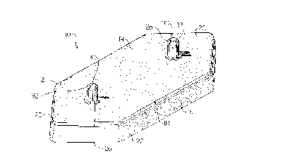
FIGURE 1 is a perspective view of a landscaping block
constructed in accordance with the tP~hinqs of the present
invention.
FIGURE 2 is a side elevation view of the l~n~ rinq block
illustrated in FIGURE 1.
FIGURE 3 is a top plan view of the l~n~ ring block
illustrated in FIG~RE 1.
EIGURE 4 is an end elevation view of the l~n~ r;nq block
illustrated in FIGURE 1.
FIGURE 5 is a bottom plan view side elevation view of the
lAn~c~rinq block illustrated in FIGURE 1.

2 1 849~8
.
side elevation view, in section, of a plurality of landscaping
FIGURE 6 is a side elevation view, in section, of a
plurality of blocks as illustrated in FIGURE 1 interlocked to
form a wall.
.J~ ;nlr ~ l~ OF THE r.~3rrnlu3~ ... _~
The preferred '; ~, a polymer plastic l~n~Rr~r;ng
block g~n~r~11y identified by reference numeral 10, will now
be ~PR~r;h~d with reference to FIGURES 1 through 6.
Referring to FIGUR~ n~R~p;ng block 10 includes a
polymer plastic shell form body 12 having an elongated
hexagonal planar top plate 14 with a peripheral edge 16. Top
plate 14 has an ~ g~t~d trunk portion 18 and opposed
generally converging ends 20 that are smaller than trunk 18.
A skirt 22 depends from p~r;ph~ral edge 16 of top plate 14.
Referring to FIGURE 5, it can be seen that skirt 22 defines
~fin;ng an underlying cavity 24. A pair of tubular bodies 26
extend through top plate 14 in space relation. It is preferred
that tubular bodies 26 be positioned where trunk portion 18
meets converging ends 20. Referring to FIGURES 3 and 5, each
one of tubular bodies 26 has an interior bore 30, a first end
32 as illustrated in FIGURE 3 and a second end 34 a3
illustrated in FIGURE 5. Referring to FIGURE 2, first end 32
extends above top plate 14. Referring to FIGURE 5, second end
34 extends below top plate within ~p~n~;ng skirt 22.
Referring to FIGURE 6, first ends 32 of tubular bodies 26 are
sized to be t~l~Rc~ri~lly received within interior bore 30 at
second end 34 of tubular bodies 26. This allows two or more
of l~n~Rc~ping blocks 10 to be interlocked as will hereinafter
be further described. Referring to FIGURES 1 through 4,
annular bearing surfaces 36 are positioned on top plate 14
encircling each of tubular bodies 26. First end 32 of each of
tubular bodies 26 has an annular interlock collar 38 that is
split into a plurality of segments 40. Referring to FIGURE 6,
interior bore 30 at second end 34 of each of tubular bodies 26
has a circumferential rib 42 which engages annular interlock

~ 1 84~18
.
collar 38. When a plurality of landscaping blockli 10 are
interlocked, interior bores 30 of tubular bodies 26 of each of
1 ~n~ ri ng blocks 10 are in register. This is important as
it enables landscaping blocks 10 to be secured to a ground
5 surface with ground 8pike8 44 after assembly.
The use of 1 ~n~ pi ng blocks 10 will now be described
with reference to FIGURES 1 through 6. Referring to FIGURE 6,
1 ~n~ pi ng blockg 10 are intended for use in construction a
10 wall. The preferred method of constructing a wall of
l~n~ ring blockg 10 involves the following steps. Firstly,
provide a plurality of polymer plastic l~nrl~c~ring blocks, as
described above. Secondly, join each of l~n~l~cAr;ng blocks 10
to two other of the li?nrlf:~r;ng blocks 10' and 10'' in
15 ~taggered fashion by inserting first end 32 of tubular bodies
26 of 1~n~l~cAring block 10 into interior bores 30 at second end
34 of tubular bodies 26 of l~n~c~ring blocks 10' and 10''.
When first end 32 is inserted into interior bore 30 at second
end 34 annular interlock collar 38 engages circumferential rib
20 42. Interlock collar 38 is able to slide past circumferential
rib 42 as 8~_ ~3 40 permit interlock collar 38 to compress.
After interlock collar has moved pa~t circumferential rib 42,
segments 40 resiliently return to their original position. By
interlocking a l3nff;~;~n~ number of l~n~lq~Ar;nq blocks 10 in
25 this fashion, a wall of a desired height and length is formed.
13ven after 1 ~nrl~ r; ng blocks 10 are interlocked, converging
ends 20 allow the wall to be conf; gllred to a desired shape.
Thirdly, once the wall is in a desired c~nf; gllrAtion~ ground
spikes 44 are inserted through interior bores 30 of tubular
30 bodies 26 of the stacked and interlocked l~n~l~c~r;ng blocks to
secure the wall to the ground. The l~ntl~c~ring blocks, being
made of polymer plastic, as light weight. In the absence of
an ability to anchor the wall to the ground using spikes 44,
the wall would change its configuration every time it was
35 bumped. There would also be a danger of straight sections of
wall being blown over by high winds. In order to make the wall
more aesth~f;r!~lly rl ~ing, it can be f;n;f~h~d through the use

2 1 849~8
of interlocking top cap3 46.
It will be apparent to one 3killed in the art that
'if;~nt jnn~ may be made to the illustrated: 1; L without
departing from the 3pirit and 3cope of the invention a~
hereinafter defined in the Claim3.

Representative Drawing
A single figure which represents the drawing illustrating the invention.
Administrative Status

2024-08-01:As part of the Next Generation Patents (NGP) transition, the Canadian Patents Database (CPD) now contains a more detailed Event History, which replicates the Event Log of our new back-office solution.

Please note that "Inactive:" events refers to events no longer in use in our new back-office solution.

For a clearer understanding of the status of the application/patent presented on this page, the site Disclaimer , as well as the definitions for Patent , Event History , Maintenance Fee  and Payment History  should be consulted.

Event History

Description Date
Inactive: IPC from MCD 2006-03-12
Inactive: Cover page published 2000-12-20
Application Not Reinstated by Deadline 1999-09-07
Time Limit for Reversal Expired 1999-09-07
Deemed Abandoned - Failure to Respond to Maintenance Fee Notice 1998-09-08
Application Published (Open to Public Inspection) 1998-03-07

Abandonment History

Abandonment Date Reason Reinstatement Date
1998-09-08
Owners on Record

Note: Records showing the ownership history in alphabetical order.

Current Owners on Record
SNAP BLOCK INC.
Past Owners on Record
DAVID BRENT LAMBERT
Past Owners that do not appear in the "Owners on Record" listing will appear in other documentation within the application.
Documents

To view selected files, please enter reCAPTCHA code :


To view images, click a link in the Document Description column (Temporarily unavailable). To download the documents, select one or more checkboxes in the first column and then click the "Download Selected in PDF format (Zip Archive)" or the "Download Selected as Single PDF" button.

List of published and non-published patent-specific documents on the CPD .

If you have any difficulty accessing content, you can call the Client Service Centre at 1-866-997-1936 or send them an e-mail at CIPO Client Service Centre.

({010=All Documents, 020=As Filed, 030=As Open to Public Inspection, 040=At Issuance, 050=Examination, 060=Incoming Correspondence, 070=Miscellaneous, 080=Outgoing Correspondence, 090=Payment})


Document
Description 
Date
(yyyy-mm-dd) 
Number of pages   Size of Image (KB) 
Representative drawing 1998-03-16 1 12
Abstract 1996-12-16 1 28
Claims 1996-12-16 4 147
Description 1996-12-16 5 197
Drawings 1996-12-16 4 102
Representative drawing 2000-12-07 1 12
Reminder of maintenance fee due 1998-05-06 1 111
Courtesy - Abandonment Letter (Maintenance Fee) 1998-10-05 1 184