Sélection de la langue

Search

Sommaire du brevet 2184948 

Énoncé de désistement de responsabilité concernant l'information provenant de tiers

Une partie des informations de ce site Web a été fournie par des sources externes. Le gouvernement du Canada n'assume aucune responsabilité concernant la précision, l'actualité ou la fiabilité des informations fournies par les sources externes. Les utilisateurs qui désirent employer cette information devraient consulter directement la source des informations. Le contenu fourni par les sources externes n'est pas assujetti aux exigences sur les langues officielles, la protection des renseignements personnels et l'accessibilité.

Disponibilité de l'Abrégé et des Revendications

L'apparition de différences dans le texte et l'image des Revendications et de l'Abrégé dépend du moment auquel le document est publié. Les textes des Revendications et de l'Abrégé sont affichés :

  • lorsque la demande peut être examinée par le public;
  • lorsque le brevet est émis (délivrance).
(12) Demande de brevet: (11) CA 2184948
(54) Titre français: BLOC D'AMENAGEMENT PAYSAGER EN PLASTIQUE POLYMERE
(54) Titre anglais: POLYMER PLASTIC LANDSCAPING BLOCK
Statut: Réputée abandonnée et au-delà du délai pour le rétablissement - en attente de la réponse à l’avis de communication rejetée
Données bibliographiques
(51) Classification internationale des brevets (CIB):
  • E04C 01/00 (2006.01)
  • E02D 29/02 (2006.01)
  • E04B 02/02 (2006.01)
  • E04C 01/39 (2006.01)
(72) Inventeurs :
  • LAMBERT, DAVID BRENT (Canada)
(73) Titulaires :
  • SNAP BLOCK INC.
(71) Demandeurs :
  • SNAP BLOCK INC. (Canada)
(74) Agent: DOUGLAS B. THOMPSONTHOMPSON, DOUGLAS B.
(74) Co-agent:
(45) Délivré:
(22) Date de dépôt: 1996-09-06
(41) Mise à la disponibilité du public: 1998-03-07
Licence disponible: S.O.
Cédé au domaine public: S.O.
(25) Langue des documents déposés: Anglais

Traité de coopération en matière de brevets (PCT): Non

(30) Données de priorité de la demande: S.O.

Abrégés

Abrégé anglais


A polymer plastic landscaping block includes a polymer
plastic shell form body having a planar top plate with a
peripheral edge. A skirt depends from the peripheral edge of
the top plate thereby defining an underlying cavity. A pair
of tubular bodies extend through the top plate in space
relation. Each one of the tubular bodies has an interior bore,
a first end extending above the top plate and a second end
extending below the top plate within the skirt. The first end
of the tubular bodies being sized to be telescopically received
within the interior bore at the second end of the tubular
bodies, thereby allowing two or more blocks to be interlocked
by mating the first end of one of the tubular bodies of one
block with the interior bore at the second end of one of the
tubular bodies of another block. When a plurality of the blocks
are interlocked, the interior bores of the tubular bodies of
each of the blocks are in register enabling the polymer plastic
landscaping blocks to be secured to the ground with ground
spikes after assembly.

Revendications

Note : Les revendications sont présentées dans la langue officielle dans laquelle elles ont été soumises.


THE EMBODIMENTS OF THE INVENTION IN WHICH AN EXCLUSIVE PROPERTY
OR PRIVILEGE IS CLAIMED ARE DEFINED AS FOLLOWS:
1. A polymer plastic landscaping block, comprising:
a polymer plastic shell form body having a planar top
plate with a peripheral edge;
a skirt depends from the peripheral edge of the top plate
thereby defining an underlying cavity;
a pair of tubular bodies extend through the top plate in
space relation, each one of the tubular bodies has an interior
bore, a first end extending above the top plate and a second
end extending below the top plate within the skirt, the first
end of the tubular bodies being sized to be telescopically
received within the interior bore at the second end of the
tubular bodies.
2. The polymer plastic landscaping block as defined in Claim
1, wherein the top plate has an elongated trunk, opposed
generally converging ends that are smaller than the trunk.
3. The polymer plastic landscaping block as defined in Claim
1, wherein the top plate is a hexagon.
4. The polymer plastic landscaping block as defined in Claim
1, wherein annular bearing surfaces are positioned on the top
plate encircling each of the tubular bodies.
5. The polymer plastic landscaping block as defined in Claim
1, wherein the first end of each of the tubular bodies has an
annular interlock collar that is split into a plurality of
segments.
6. The polymer plastic landscaping block as defined in Claim
5, wherein the interior bore at the second end of each of the
tubular bodies has means for engaging the annular interlock
collar.

7. A polymer plastic landscaping block, comprising:
a polymer plastic shell form body having an elongated
planar top plate with a peripheral edge, the top plate having
an elongated trunk and opposed generally converging ends that
are smaller than the trunk;
a skirt depends from the peripheral edge of the top plate
thereby defining an underlying cavity;
a pair of tubular bodies extend through the top plate in
space relation, each one of the tubular bodies has an interior
bore, a first end extending above the top plate and a second
end extending below the top plate within the skirt, the first
end of the tubular bodies being sized to be telescopically
received within the interior bore at the second end of the
tubular bodies;
the first end of each of the tubular bodies has an annular
interlock collar that is split into a plurality of segments;
and
the interior bore at the second end of each of the tubular
bodies has means for engaging the annular interlock collar.
8. The polymer plastic landscaping block as defined in Claim
7, wherein the top plate is a hexagon.
9. The polymer plastic landscaping block as defined in Claim
7, wherein annular bearing surfaces are positioned on the top
plate encircling each of the tubular bodies.

10. A method of constructing a wall of polymer plastic
landscaping blocks, comprising the steps of:
firstly, providing a plurality of polymer plastic
landscaping blocks including:
a polymer plastic shell form body having an elongated
planar top plate with a peripheral edge, the top plate having
an elongated trunk and opposed generally converging ends that
are smaller than the trunk;
a skirt depends from the peripheral edge of the top
plate thereby defining an underlying cavity;
a pair of tubular bodies extend through the top plate
in space relation, each one of the tubular bodies has an
interior bore, a first end extending above the top plate and
a second end extending below the top plate within the skirt,
the first end of the tubular bodies being sized to be
telescopically received within the interior bore at the second
end of the tubular bodies;
secondly, joining each of the landscaping blocks to two
other of the landscaping blocks in staggered fashion by
inserting the first end of the tubular bodies into the interior
bores at the second end of one of the tubular bodies of two
other of the landscaping blocks until a wall of a desired
height and length is formed;
thirdly, inserting a plurality of ground spikes at
intervals along the wall through the interior bores of the
tubular bodies of a plurality of stacked and interlocked
landscaping blocks, thereby securing the wall to the ground.

11. A wall constructed of polymer plastic landscaping blocks,
comprising:
a plurality of polymer plastic landscaping blocks
including:
a polymer plastic shell form body having an elongated
planar top plate with a peripheral edge, the top plate having
an elongated trunk and opposed generally converging ends that
are smaller than the trunk;
a skirt depends from the peripheral edge of the top
plate thereby defining an underlying cavity;
a pair of tubular bodies extend through the top plate
in space relation, each one of the tubular bodies has an
interior bore, a first end extending above the top plate and
a second end extending below the top plate within the skirt,
the first end of the tubular bodies being sized to be
telescopically received within the interior bore at the second
end of the tubular bodies;
each of the landscaping blocks being joined to two other
of the landscaping blocks in staggered fashion by inserting the
first end of the tubular bodies of the landscaping blocks into
the interior bores at the second end of two other of the
landscaping blocks until a wall of a desired height and length
is formed;
a plurality of ground spikes being inserted at intervals
along the wall through the interior bores of the tubular bodies
of a plurality of stacked and interlocked landscaping blocks,
thereby securing the wall to the ground.

Description

Note : Les descriptions sont présentées dans la langue officielle dans laquelle elles ont été soumises.

21 84948
.~
TITLE OF T~
polymer plastic l~n~ ring block
NAME OF L~v~ . ~):
David Brent Lambert
FIELD OF THE lhv~ ~
The present invention relates to a polymer pla3tic
1 An~CAp; n~ block
P~ OF THE 1~
United States Patent 4,905,409 entitled "Landscaping
Timber" which issued to Cole in 1990 discloses a modern day
~yL~a~h to the bni l~;ng of retaining walls and decorative
borders. The patent discloses a trapezoidal shaped timber,
which can be c ';n~d with other, like timbers, to form
re~-~;n;ng walls and decorative borders in an infinite variety
of shapes.
United States Patent 4,965,979 entitled "Concrete slock
Wall" which issued to Larrivee et al in 1990 discloses an
interlocking concrete block that has radiused ends which can
be used to form retaining wall3 and decorative borders in a
manner similar to the Cole reference. Unfortunately, concrete
blocks are a relatively expensive material to use for retaining
walls and decorative borders.
SUMMARY OF THE INVP~'TTON
What is required is a low cost polymer plagtic lAn~RcAring
block.
According to one aspect of the present invention there is
provided a polymer plastic lAn~CAring block which ;n~ e~ a
, _ . . _ _ . .. . . _ _ _ . _ _ _

2 1 B4~4~
polymer plastic shell form body having a planar top plate with
a pPr;ph~ral edge. A skirt depends from the p~r; rhPral edge
of the top plate thereby ~fininq an underlying cavity. A pair
of tubular bodies extend through the top plate in space
relation. Each one of the tubular bodies has an interior bore,
a first end extending a_ove the top plate and a second end
extending below the top plate within the skirt. The first end
of the tubular bodies being sized to be telPscor~ ly received
within the intprinr bore at the second end of the tubular
bodies, thereby allowing two or more blocks to be interlocked
by mating the first end of one of the tubular bodies of one
block with the interior bore at the second end of one of the
tubular bodies of another block.
The polymer plastic lAn~ ring block, as described above,
is a low cost alternative to concrete blocka. When a plurality
of the blocks are interlocked, the interior bores of the
tubular bodies of each of the blocks are in register Pn~hlinq
the polymer plastic landscaping blocks to be secured to the
ground with ground spikes after assembly.
P~T~ OF THE ~KAW
These and other feature~ of the invention will become more
apparent from the following description in which reference is
made to the ArpPn~Pd drawings, wherein:
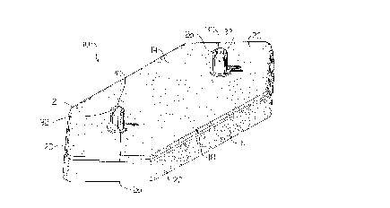
FIGURE 1 is a perspective view of a landscaping block
constructed in accordance with the tP~hinqs of the present
invention.
FIGURE 2 is a side elevation view of the l~n~ rinq block
illustrated in FIGURE 1.
FIGURE 3 is a top plan view of the l~n~ ring block
illustrated in FIG~RE 1.
EIGURE 4 is an end elevation view of the l~n~ r;nq block
illustrated in FIGURE 1.
FIGURE 5 is a bottom plan view side elevation view of the
lAn~c~rinq block illustrated in FIGURE 1.

2 1 849~8
.
side elevation view, in section, of a plurality of landscaping
FIGURE 6 is a side elevation view, in section, of a
plurality of blocks as illustrated in FIGURE 1 interlocked to
form a wall.
.J~ ;nlr ~ l~ OF THE r.~3rrnlu3~ ... _~
The preferred '; ~, a polymer plastic l~n~Rr~r;ng
block g~n~r~11y identified by reference numeral 10, will now
be ~PR~r;h~d with reference to FIGURES 1 through 6.
Referring to FIGUR~ n~R~p;ng block 10 includes a
polymer plastic shell form body 12 having an elongated
hexagonal planar top plate 14 with a peripheral edge 16. Top
plate 14 has an ~ g~t~d trunk portion 18 and opposed
generally converging ends 20 that are smaller than trunk 18.
A skirt 22 depends from p~r;ph~ral edge 16 of top plate 14.
Referring to FIGURE 5, it can be seen that skirt 22 defines
~fin;ng an underlying cavity 24. A pair of tubular bodies 26
extend through top plate 14 in space relation. It is preferred
that tubular bodies 26 be positioned where trunk portion 18
meets converging ends 20. Referring to FIGURES 3 and 5, each
one of tubular bodies 26 has an interior bore 30, a first end
32 as illustrated in FIGURE 3 and a second end 34 a3
illustrated in FIGURE 5. Referring to FIGURE 2, first end 32
extends above top plate 14. Referring to FIGURE 5, second end
34 extends below top plate within ~p~n~;ng skirt 22.
Referring to FIGURE 6, first ends 32 of tubular bodies 26 are
sized to be t~l~Rc~ri~lly received within interior bore 30 at
second end 34 of tubular bodies 26. This allows two or more
of l~n~Rc~ping blocks 10 to be interlocked as will hereinafter
be further described. Referring to FIGURES 1 through 4,
annular bearing surfaces 36 are positioned on top plate 14
encircling each of tubular bodies 26. First end 32 of each of
tubular bodies 26 has an annular interlock collar 38 that is
split into a plurality of segments 40. Referring to FIGURE 6,
interior bore 30 at second end 34 of each of tubular bodies 26
has a circumferential rib 42 which engages annular interlock

~ 1 84~18
.
collar 38. When a plurality of landscaping blockli 10 are
interlocked, interior bores 30 of tubular bodies 26 of each of
1 ~n~ ri ng blocks 10 are in register. This is important as
it enables landscaping blocks 10 to be secured to a ground
5 surface with ground 8pike8 44 after assembly.
The use of 1 ~n~ pi ng blocks 10 will now be described
with reference to FIGURES 1 through 6. Referring to FIGURE 6,
1 ~n~ pi ng blockg 10 are intended for use in construction a
10 wall. The preferred method of constructing a wall of
l~n~ ring blockg 10 involves the following steps. Firstly,
provide a plurality of polymer plastic l~nrl~c~ring blocks, as
described above. Secondly, join each of l~n~l~cAr;ng blocks 10
to two other of the li?nrlf:~r;ng blocks 10' and 10'' in
15 ~taggered fashion by inserting first end 32 of tubular bodies
26 of 1~n~l~cAring block 10 into interior bores 30 at second end
34 of tubular bodies 26 of l~n~c~ring blocks 10' and 10''.
When first end 32 is inserted into interior bore 30 at second
end 34 annular interlock collar 38 engages circumferential rib
20 42. Interlock collar 38 is able to slide past circumferential
rib 42 as 8~_ ~3 40 permit interlock collar 38 to compress.
After interlock collar has moved pa~t circumferential rib 42,
segments 40 resiliently return to their original position. By
interlocking a l3nff;~;~n~ number of l~n~lq~Ar;nq blocks 10 in
25 this fashion, a wall of a desired height and length is formed.
13ven after 1 ~nrl~ r; ng blocks 10 are interlocked, converging
ends 20 allow the wall to be conf; gllred to a desired shape.
Thirdly, once the wall is in a desired c~nf; gllrAtion~ ground
spikes 44 are inserted through interior bores 30 of tubular
30 bodies 26 of the stacked and interlocked l~n~l~c~r;ng blocks to
secure the wall to the ground. The l~ntl~c~ring blocks, being
made of polymer plastic, as light weight. In the absence of
an ability to anchor the wall to the ground using spikes 44,
the wall would change its configuration every time it was
35 bumped. There would also be a danger of straight sections of
wall being blown over by high winds. In order to make the wall
more aesth~f;r!~lly rl ~ing, it can be f;n;f~h~d through the use

2 1 849~8
of interlocking top cap3 46.
It will be apparent to one 3killed in the art that
'if;~nt jnn~ may be made to the illustrated: 1; L without
departing from the 3pirit and 3cope of the invention a~
hereinafter defined in the Claim3.

Dessin représentatif
Une figure unique qui représente un dessin illustrant l'invention.
États administratifs

2024-08-01 : Dans le cadre de la transition vers les Brevets de nouvelle génération (BNG), la base de données sur les brevets canadiens (BDBC) contient désormais un Historique d'événement plus détaillé, qui reproduit le Journal des événements de notre nouvelle solution interne.

Veuillez noter que les événements débutant par « Inactive : » se réfèrent à des événements qui ne sont plus utilisés dans notre nouvelle solution interne.

Pour une meilleure compréhension de l'état de la demande ou brevet qui figure sur cette page, la rubrique Mise en garde , et les descriptions de Brevet , Historique d'événement , Taxes périodiques et Historique des paiements devraient être consultées.

Historique d'événement

Description Date
Inactive : CIB de MCD 2006-03-12
Inactive : Page couverture publiée 2000-12-20
Demande non rétablie avant l'échéance 1999-09-07
Le délai pour l'annulation est expiré 1999-09-07
Réputée abandonnée - omission de répondre à un avis sur les taxes pour le maintien en état 1998-09-08
Demande publiée (accessible au public) 1998-03-07

Historique d'abandonnement

Date d'abandonnement Raison Date de rétablissement
1998-09-08
Titulaires au dossier

Les titulaires actuels et antérieures au dossier sont affichés en ordre alphabétique.

Titulaires actuels au dossier
SNAP BLOCK INC.
Titulaires antérieures au dossier
DAVID BRENT LAMBERT
Les propriétaires antérieurs qui ne figurent pas dans la liste des « Propriétaires au dossier » apparaîtront dans d'autres documents au dossier.
Documents

Pour visionner les fichiers sélectionnés, entrer le code reCAPTCHA :


Pour visualiser une image, cliquer sur un lien dans la colonne description du document (Temporairement non-disponible). Pour télécharger l'image (les images), cliquer l'une ou plusieurs cases à cocher dans la première colonne et ensuite cliquer sur le bouton "Télécharger sélection en format PDF (archive Zip)" ou le bouton "Télécharger sélection (en un fichier PDF fusionné)".

Liste des documents de brevet publiés et non publiés sur la BDBC .

Si vous avez des difficultés à accéder au contenu, veuillez communiquer avec le Centre de services à la clientèle au 1-866-997-1936, ou envoyer un courriel au Centre de service à la clientèle de l'OPIC.

({010=Tous les documents, 020=Au moment du dépôt, 030=Au moment de la mise à la disponibilité du public, 040=À la délivrance, 050=Examen, 060=Correspondance reçue, 070=Divers, 080=Correspondance envoyée, 090=Paiement})


Description du
Document 
Date
(aaaa-mm-jj) 
Nombre de pages   Taille de l'image (Ko) 
Dessin représentatif 1998-03-16 1 12
Abrégé 1996-12-16 1 28
Revendications 1996-12-16 4 147
Description 1996-12-16 5 197
Dessins 1996-12-16 4 102
Dessin représentatif 2000-12-07 1 12
Rappel de taxe de maintien due 1998-05-06 1 111
Courtoisie - Lettre d'abandon (taxe de maintien en état) 1998-10-05 1 184