Note: Descriptions are shown in the official language in which they were submitted.
2 1 85076
TITLE OF THE INVENTION:
heat exchanger for a hydrocarbon fuelled motor vehicle
NAME OF INVENTOR):
Easton Bennett
FIELD OF THE INVENTION
The present invention relates to a heat exchanger for a
hydrocarbon fuelled motor vehicle.
R~ ROUND OF THE INVENTION
Heat is generated when a hydrocarbon fuel is burned in an
engine. This heat is vented to atmosphere, along with other
products of combustion, through exhaust pipes. German Patent
28 29 454 which issued to Klockner-Humbolt-Deutz in 1983,
discloses a heat exchanger which is adapted to fit around an
exhaust pipe. The heat exchanger works in conjunction with a
tank supplying water for a car heater. Controls are provides
to ensure that the water in the tank neither freezes nor boils.
When the temperature approaches freezing, the controls divert
the water through the heat exchanger for heating.
Due to space limitations, the heat exchanger disclosed in
the German patent, cannot be readily be installed in most
modern motor vehicles.
SUMMARY OF THE INVENTION
What is required is a heat exchanger for a hydrocarbon
2 1 85076
fuelled motor vehicle that can be installed on modern
automobiles notwithst~n~;ng space limitations.
According to one aspect of the present invention there is
provided a heat exchanger for a hydrocarbon fuelled motor
vehicle. The heat exchanger includes an exhaust pipe and a
length of conduit formed into a heat exchange coil by wrapping
several times around the exhaust pipe. The conduit has a first
end and a second end, whereby the conduit is connected to a
fluid circulation conduit.
The heat exchanger, as described above, allows the heat
from the exhau~t pipe to be transferred to the heat exchange
coil for use elsewhere on the vehicle where heat is required.
According to another aspect of the present invention,
there is provided a combination which includes an engine, a
heater core, an exhaust pipe, and a closed loop fluid
circulation conduit. The closed loop fluid circulation conduit
is connected to the engine and the heater core, and includes
a length of conduit formed into a heat exchange coil by
wrapping several times around the exhaust pipe.
The combination, as described above, makes use of the heat
captured by the heat exchange coil to enhance the operation of
the vehicle's heater. The heater of a motor vehicle does not
operate properly in cold weather until the engine of the motor
vehicle has had sufficient time to warm up. This combination
reduces the time required to get the heater fully operational.
Although beneficial results may be obtained through the
use of the combination, as described above, once the motor
vehicle warms up there can be excessive heat. It is,
therefore, preferred that the closed loop fluid circulation
conduit include a bypass conduit and valves to control the
relative flow of fluids through the bypass conduit and the heat
exchange coil.
2 1 85076
BRIEF ~ ~RTPTION OF THE DRAWINGS
These and other features of the invention will become more
apparent from the following description in which reference is
made to the appended drawings, wherein:
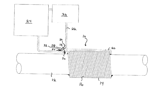
FIGURE 1 is a schematic representation of a heat exchanger
for a hydrocarbon fuelled motor vehicle constructed in
accordance with the teachings of the present invention.
DE~TT-~n nr~CPTPTION OF THE ln~nK~ EMBODI~ENT
The preferred embodiment, a heat exchanger for a
hydrocarbon fuelled motor vehicle generally identified by
reference numeral 10, will now be described with reference to
FIGURE 1.
Heat exchanger 10 includes an exhaust pipe 12 and a length
of conduit 14 formed into a heat exchange coil 16 by wrapping
several times around exhaust pipe 12. Conduit 14 has a first
end 18 and a second end 20, whereby conduit 14 is connected to
a fluid circulation conduit, such as fluid circulation conduit
22.
Heat exchanger 10 is intended for use in combination with
an engine 24 and a heater core 26. First end 18 and second end
20 of conduit 14 are connected to fluid circulation conduit 22.
Fluid circulation conduit is a closed loop fluid circulation
conduit which enables fluid to be circulation from engine 24
through heater core 26 and then back to engine 24. When
combined, as illustrated, excess heat from exhaust pipe 12 is
transferred via heat exchange coil 16 to fluid circulation
conduit 22. This heats the working fluid for heater core 26
more rapidly than would otherwise be possible and, thereby,
enhances the operation of the vehicle's heater. The heater is
21 85076
fully operation in cold weather, in less time.
In order to avoid excessive heat, it is preferred that
fluid circulation conduit 22 include a bypass conduit 28 and
solenoid valves 30 and 32. Bypass conduit 28 has a first end
34 and a second end 36. Solenoid valve 30 is positioned at
first end 18 of conduit 14 to control the flow of fluids
through heat exchange coil 16. Solenoid valve 32 is positioned
at first end 34 of bypass conduit 28 to control the flow of
fluids through bypass conduit 28. When solenoid valve 32 is
closed and solenoid valve 30 is open, all fluid flowing through
fluid circulation conduit 22 passes through heat exchange coil
16. This heats up fluids going to heater core 26 as rapidly
as possible for cold operating conditions. When solenoid valve
30 is closed and solenoid valve 32 is open, all fluid flowing
through fluid circulation conduit 22 goes via bypass conduit
28, bypassing heat exchange coil 16. This mode is used when
extra heat is unnecessary or undesirable. It is technically
possible, with appropriate valving to have a mixed stream with
relative portions of the fluid in fluid circulation conduit
passing through bypass conduit 28 and heat exchange coil 16.
It will be apparent to one skilled in that art that the
heat exchanger will save time and fuel when warming up a motor
vehicle prior to use in cold weather. It will also be apparent
to one skilled in that art that the head exchanger, as
described, can be installed in most motor vehicles
notwithst~n~;ng severe space limitations. It will finally be
apparent to one skilled in the art that modifications may be
made to the illustrated embodiment without departing from the
spirit and scope of the invention as hereinafter defined in the
Claims.