Note: Descriptions are shown in the official language in which they were submitted.
2185282
~ ~;
DUTCH OVEN TYPE COOKING VESSEL WITH COMBINATION COOKING SURFACE
TECHNICAL FIELD OF THE INVENTION
This invention relates to a novel dutch oven type
cooking apparatus. More particularly, it relates to a dutch
oven type cooking apparatus which has a bottom cooking pan
portion and an upper top or lid portion, wherein the upper
portion is convertible from a cooker pan lid to a stand alone
grille.
BACKGROUND
In institutional and commercial kitchens, there is a
continuing need to cook foods using different cooking
methods. For example, at breakfast, the main meals may be
cooked on a grille, but then at lunch or dinner, it may be
desirable to deep fry, roast, or simply heat the foods in
bulk. Normally, it is necessary to have a variety of
different kitchen equipment available, each of which may be
used to prepare foods by only one or two cooking techniques.
Therefore, multiple equipment items, such as separate
grilles, ovens, pans, and kettles are often found in such
kitchens. The requirement for multiple equipment increases
-1-
z~ ~~z~2~;
both the initial capital costs, and the floor space
requirements for food preparation kitchens, thus increasing
the ultimate cost of food preparation in the kitchen. Thus,
particularly in those cooking operations where equipment
costs or space constraints are most sensitive, it would be
desirable to reduce the number of separate equipment items
required. In short, it would be preferable to combine the
function of several types of equipment into a single cooking
apparatus rather than to limit the menu or reduce capital
costs by eliminating certain cooking techniques from the
kitchen altogether.
One attempt at a combination type device of which I am
aware is illustrated in U.S. Patent No. 2,430,582, issued
Nov. 11, 1947 to Reich for HEATING DEVICE. That patent
illustrates, in FIGS. 9--12 and FIGS. 15-17, a cooking device
such as a grille which has an upper frame with a pivoting
electrical heater to provide from one side direct radiant
heat and from the other side conducted heat (through a metal
plate); thus this device can be used as a grille or as a
broiler.
-2-
~~ 2~852~2~:'
Another device is illustrated in U.S. Patent No.
4,957,039, issued September 18, 1990 to Reyes for a FIVE IN
ONE COOKER. Reyes illustrates a swivel top portion which can
be inverted from a dome configuration where the dome is used
as a lid to control the heating of barbecue on grilles below,
or to a pan configuration so that food can be cooked in the
pan. However, in so far as I am aware, no institutional type
dutch oven cookers have been proposed which allow flexibility
to switch between cook and grille configurations.
Therefore, a continuing demand exists for a simple,
space saving, and relatively inexpensive cooking apparatus
which can be used as desired in many different cooking modes.
The need for such devices is commonly seen in institutional
settings, such as hospitals, prisons, nursing homes, or in
commercial restaurant settings, particularly where space is
at a premium.
-3-
CA 02185282 2002-06-21
I have now invented, and disclose herein, a novel, improved
cooking vessel which does not have the above-discussed drawbacks
common to those heretofore used cooking devices of which I am
aware. Unlike cookers heretofore available, my cooking vessel
is compact, relatively inexpensive, easy to install and to
service, and otherwise superior to the heretofore proposed ones.
Most importantly, it is easy to switch between various cooking
modes.
The invention in one broad aspect provides an apparatus for
heating foods, liquids, or slurries, the apparatus comprising a
lower portion, a bottom pan portion, the bottom pan portion
supported by the lower frame portion, and an upper frame,
pivotally supported from the bottom pan portion. A top portion
is pivotally affixed to the upper frame, and the top portion
includes a lid portion and a grille portion. The upper frame
further comprises a left end having a first pivot, and a right
end, the right end having a second pivot, wherein the first and
second pivots cooperate to allow the top portion to be rotated
thereabout when the upper frame is raised, from a closed, fitting
position, wherein the lid portion of the top portion is
interfittingly located at the bottom pan portion, to an extended,
open position, wherein the upper frame is suf f iciently upward so
that the top portion is rotatable so as to interchange positions
of the lid portion and the grille portion. The top portion is
shaped such that the lid portion is nestable in the bottom pan
portion when the upper frame is returned to the closed, fitting
position.
Another aspect of the invention provides a cooking apparatus
having a top portion and a bottom pan portion, the apparatus
configured to supply heating fluid to the top portion or to the
top and bottom portions thereof. The apparatus comprises a top
portion, comprising at least one inlet and at least one outlet,
and a bottom pan portion, comprising at least one inlet and at
least one outlet. A first fluid passageway comprises a conduit
between the inlet and the outlet in the top portion, and a second
fluid passageway, comprises a conduit between the inlet and the
outlet in the bottom pan portion. A regulator regulates the
passage of heating fluid into the lid portion and into the bottom
-4
CA 02185282 2002-06-21
pan portion, in a first, single fluid flow relationship wherein
heating fluid is allowed to flow through the first fluid
passageways, or in a second, multiple fluid flow relationship
wherein heating fluid is allowed to flow through the fluid
passageway in the top portion and in the bottom portion.
More particularly the apparatus of the invention provides
for heating foods, liquids, or slurries and includes a lower
frame portion, and a lower pan portion which is supported by the
lower frame portion. An upper frame portion is pivotally
supported from the lower pan port ion . A top or upper compartment
portion is provided, the top portion being pivotally affixed to
the left and right sides of the upper frame portion.
The top portion includes a lid portion and a grille portion.
In the preferred embodiment, the grille portion of the top
portion is the inner wall surface of the lid portion, and is thus
located in the upper reaches of the top portion when the lid
portion is in a cooking position. When the top is rotated one
hundred eighty (180) degrees, the grille portion provides an
upwardly exposed grille surface for food preparation. Also, the
top portion is shaped such that it may be lowered into and nested
in the bottom portion when the upper frame portion has been
returned to a resting or normal closed cooking position.
When hot oil or other fluid is used to heat the cooking
apparatus, the bottom or lower pan portion further comprises a
double wall portion. The double wall portion includes an inner
and an outer wall which form a passageway therebetween. The
passageway has an inlet and an outlet for the heating fluid to
enter and leave the passageway. Heating fluid heats the inner
wall which thus heats the food being cooked. The top portion
also further includes a double exterior wall portion, where the
double wall portion includes an inner and an outer wall with a
passageway therebetween. The passageway has an inlet and an
outlet, whereby a heating fluid may be passed into the passageway
in the bottom pan portion, or into the passageway in the top
portion, or simultaneously into the bottom pan portion and the
top portion passageways, so as to heat the foods, liquids, or
slurries contained by the cooking apparatus.
-5-
CA 02185282 2002-06-21
Thus it can be seenthat my dutch oven type cook system
cooks from all sides Withhot oil. Alternately, the unit
may
be heated electrically. The tilt type upper frame and the
versatile convertible top portion allow my cooking apparatus
to bake, roast, fry, braise, broil, saute, steam, or kettle
cook. The apparatus may also grille in the short order
style. A bottom draw off is provided to allow pumping of
cooked food into cryovac casings or pouches for ice water
chill of cryovac casings, or for blast chill of the pan
contents.
The various embodiments provide further variations in
the heating configuration and in provision of the heating
means. Aside from the foregoing, my novel cooking apparatus
is simple, durable, and relatively inexpensive to
manufacture.
ADVANTAGES AND FEATURES
The apparatus of the present invention has numerous
significant advantages over the apparatus currently used in
institutional and commercial cooking operations. From the
forgoing, it will be apparent to the reader that one
important and primary object of the present invention is to
provide a single, multipurpose cooking apparatus which allows
foods to be cooked in any one of a variety of selected
techniques, where the list of possible cooking techniques
_6_
21~52~2
which may be selected includes baking, roasting, frying,
braising, broiling, grilling, steaming, or kettle cooking.
Other important but more specific objects and advantages
of the invention reside in the provision of a cooking device
as described in the preceding paragraph which:
may be quickly converted from either a
pressure cooker to a grille, or vice-versa;
may be used as a steamer;
may be used as a stir fry pan;
may be used as a broiler;
is relatively compact and thereby conserves
space;
is relatively simple;
is relatively inexpensive;
allows the foods to be discharged from the
apparatus in a simple, one step manner;
2185282
Other important objects, features, and additional
advantages of my invention will become apparent to the
reader from the foregoing and the appended claims and
as the ensuing detailed description and discussion
proceeds in conjunction with the accompanying drawing.
DRAWINGS
These and other features, aspects and advantages of
the present invention will become better understood
with reference to the following description, appended
claims, and accompanying drawings, wherein:
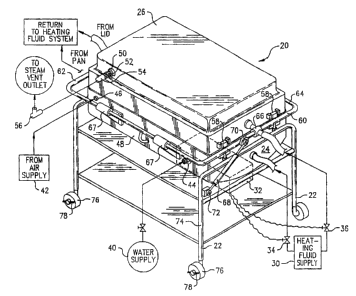
Figure 1 is a perspective view of a cooking
apparatus constructed in accord with the principles of
the present invention, showing the top portion in a
position for baking, roasting, broiling, or the like.
Figure 2 is a perspective view of the lower or pan
portion of a second embodiment of the cooking apparatus
constructed in accord with the principles of the
present invention, showing the use of flat segments in
the lower pan portion, and also illustrating the use of
a remote control device for setting the cook
conditions.
_g_
CA 02185282 2002-06-21
Figure 3 is a side view of a cooking apparatus
similar to that set forth in FIG. 1 above, constructed
in accord with the present invention with the upper or
top portion initially indicated in the cooker or
broiler position, and also showing in hidden lines the
upper compartment at an open position wherein the upper
compartment is being inverted to the grille position.
Figure 4 is a vertical cross sectional view of my
cooking apparatus, shown with the top compartment of
the cooking apparatus positioned in the cooking or
broiling position, and additionally showing the flow
passageways for a~heating fluid.
Figure 5 is a top plan view of the embodiment of
the cooking apparatus shown in FIG. 1 above, now with
the upper compartment opened outward horizontally in an
extended position so as to fully reveal the cooking
surfaces in both the bottom and the top portions.
Figure 6 is a third embodiment of my invention,
showing the use of a gas heating system to heat the
kettle.
_g_
2~ 85282 ~
Figure 7 is a fourth embodiment of my cooking
device, showing the use of electrical heating elements
to heat the upper and lower grilles.
In the drawing, like parts will be noted with like
reference numerals throughout the various figures,
without further comment thereon.
-lo-
2185282
DESCRIPTION
Referring now to the drawing and to the reference
characters therein, FIG. 1 depicts, in its operative
cooking position, a cooking apparatus 20 constructed in
accord with, and embodying, the principles of the
present invention.
Major components of the cooking apparatus 20
include: a lower frame or base portion 22, a bottom
pan portion 24 which is supported from the base portion
22, and a combination grille and lid top portion 26.
The top 26 is supported in a manner so that it can be
opened in order to place the food to be cooked (not
shown) into the pan portion 24, and so that the top 26
can be inverted about one hundred eighty degrees (1800)
and thereafter used as a grille, as will be further
described and illustrated herein below
In one embodiment, the top or lid portion 26 and
the bottom or pan portion 24 are each double-walled
vessels having inner and outer walls with a fluid
receiving passageway therebetween, as can be readily
seen in FIG. 4 below. Returning to FIG. 1. a heating
fluid supply source 30 provides a heating fluid such as
-11-
2~ 85282 ~.
hot oil or steam to heat the bottom pan 24 and the top
lid 26. A control unit 32 controls the supply of
heating fluid to pan 24 and lid 26 via way of
regulation devices such as valves 34 and 36
respectively.
As it may be desirable to add steam or air directly
to the interior formed between the bottom pan 24 and
1 id 2 6 of the cooking apparatus 2 0 , a water supp 1y 4 0
and an air supply 42 are provided to the cooling
apparatus 20. Preferably, connection both the water
supply 40 and air supply 42 is by way of a flexible
hose (not shown) attached to a quick connect type
fitting 44 (for water) and 46 (for air) as indicated at
the rear 48 of pan 24. Vapors resulting from both the
introduction of air or steam, or from the cooking of
foods, are allowed to escape from the interior of the
apparatus 20 and are vented through the top 26 via way
of a steam vent outlet 50. This outlet 50 is also
preferably provided via way of a quick connect fitting
52 attached to a flexible hose 54. Normally, a vent
outlet system also includes pressure regulating means
such as an adjustable pressure relief valve 56, so that
the cooking apparatus 20 may be used as a pressure
cooker. Valve 56 allows the cook to set the internal
-12-
2185282
pressure of the apparatus 20 somewhat above atmospheric
pressure up to a rated pressure such as 8 psig (and
normally not above 15 psig). When used as a pressure
cooker, the cooking apparatus 20 may have the top 26
secured to bottom pan 24 via way of snap levers or
similar fasteners 58.
As illustrated in this FIG. 1, the top 26 is
supported by, and rotates within and between the left
l0 60 and right 62 ends of upper frame 64. A pivot joint
66 at the left end 60 and companion joint 66 on right
end 62 of frame 64 provide the freedom of movement
necessary for rotation of top 26. Movement of top 26
is possible once the top is raised to an open position
as illustrated in FIG. 4 below.
The upper frame 64 is in turn supported from the
rear 48 of pan 24 by hinges 67. A combination spring
lift/shock damper 68 is positioned between a first
pivot pin 70 at upper frame 64 and a second pivot pin
72 affixed to the rear 74 of base 22. The purpose of
the shock damper 68 is primarily to prevent the top 26
from closing at an undesirably rapid rate from an open
position. Damper 68 may also assist in slightly biasing
the frame 64 toward an open position. For ease in
-13-
~ ~ 85282 c'
moving the cooking apparatus 20 between locations in a
kitchen, or to assist with access for cleaning, base 22
is provided with rollers 76, preferably with locking
mechanism 78 to prevent the cooking apparatus 20 from
moving when set at a desired location.
Attention is now directed at the rounded bottom 80
of pan 24 as shown in FIG. 1. This type of
construction may be desirable in many applications,
such as pressure cooker usage, but it generally
increases the cost of apparatus 20. In contrast, in
FIG. 2 is shown a second embodiment of my invention,
cooking apparatus 90, which is similar to apparatus 20
shown in FIG. l, but constructed with a lower pan 92
having a segmented flat bottom 94. The flat bottom 94
construction is somewhat cheaper to fabricate, and also
may be more desirable for some types of cooking such as
stir-fry or other oriental type cooking techniques.
Also in FIG. 2, the lid or top 96 is turned upside
down as compared to top 26 of FIG. 1. Therefore, in
FIG. 2, lid 96 is shown with its interior, grill
forming surface 98 upward. Quick conversion of the top
-14-
3
2185282 r
portion 96 between a lid or cooking position, as
illustrated in FIG. 1, and a grill position, as shown
in FIG. 2, by way of simple rotation of the top portion
96, is a unique and important advantage of my cooking
apparatus 20.
A remote control unit 100 is also shown in this
FIG. 2. The remote control unit 100 can be used to
program or reprogram the control unit 32 on the cooking
l0 apparatus 90. Typical remote control units 100 use an
infrared signal 102 which is broadcast from the remote
control unit 100 and is received at the control unit
32, similar to television or video recorder type remote
control units. The use of a remote control unit 100
may be especially important in some institutional
settings, such as prisons, where it may be desirable to
set or reset the cooking device independently and
without the ability of local personnel to immediately
readjust the control unit 32, so as to prevent the
occurrence of sabotage to the cooking cycle.
Turning now to FIG. 3, a side view of a cooking
apparatus 110 is shown. Apparatus 110 is similar to
the apparatus 20 first shown in FIG. 1 above, although
here a bottom drain line 112 is also shown. This line
-I5-
2185282
112 is preferably supplied in stainless steel of any
desired size to accommodate the cooking apparatus size;
for conventional sized units a nominal three inch (3")
line 112 is satisfactory. Output from the drain line
112 is controlled by a knife type valve 114, and a line
116 to an outlet pump 118 is provided. The discharge
from an outlet pump 118 may be sent to a cryovac pump
and fill type bagging system (not shown) or other
system for receiving the food slurry leaving the
cooking apparatus 110. For example, chili may be
cooked in cooking apparatus 110, and then drained
through line 112 and pumped into cryovac bags to be
cooled down in an ice bath for subsequent storage
and/or freezing. This drain 112 feature is important
since cooking apparatus 110 may be normally of a forty
(40) to eighty (80) gallon size for commercial or
institutional service, with a unit in the sixty (60)
gallon size range expected to be commonly required.
In FIG. 3 the transformation of the top portion 116
from cooking service to grill service is illustrated in
hidden lines. The top portion 116 is shown in cooking
service or a lid position in solid lines. By moving
upper frame 64 upward, in the direction of reference
arrow 115, through the position indicated by reference
-16-
"v 2185282
numeral 64' and on upward to the position indicated by
reference numeral 64 " , clearance is achieved to rotate
the top portion 116 to the grille position indicated by
reference numeral 116'. An interior grill surface 118'
is provided, which is upward when the top portion 116'
is turned upward. When the top portion is moved
downward in the direction of reference arrow 120 and
nested in the pan 122, the top portion 116 provides a
convenient grille surface 118. Note that the top
portion 116 has a lower outer sidewall portion 124
which is sized for the close fitting insertion
necessary to nest the lid 116 against the inner wall
126 (See FIG. 4 below) of the bottom pan 122.
Turning now to FIG. 4, a vertical cross section of
cooling apparatus 110 is shown. In this FIG. 4, the
double wall construction of both the bottom pan portion
122 and the top lid portion 116 are readily apparent.
Heating fluid contained in hose 150 flows enters the
lid portion 116 through inlet 152. Inlet 152 has a
fluid passageway 154 therein which communicates with
passageway 156 in lid 116. Passageway 156 is defined
between the inner 158 and outer 160 walls of lid 116.
The heating fluid circulates in passageway 156 as
indicated by reference arrow 162, so as to heat inner
-17-
2185282
wall 158. The circulating heating fluid then proceeds
through the lid 116 as indicated by reference arrow
164, then leaves lid 116 through passageway 165 in
outlet 166, thence to hose 168. During the period of
heating provided by contact of the heating fluid with
inner wall 158, sufficient heat must be applied to heat
the food on grille portion 118, or as necessary to
provide a portion of the heat required to heat the food
in the bottom pan 122 (when and as it is used).
Similar to the process just described for the lid
portion 116, heating fluid enters the lower pan 122
through hose 170 and inlet 172 having a passageway 174
therein. Heating fluid then proceeds downward in the
direction of reference arrow 176 in the passageway 178
which is defined between inner bottom wall 180 and
outer bottom wall 182. Heating fluid exits in the
direction of reference arrow 184 and proceeds through
passageway 186 in outlet 188, thence on through outlet
hose 190. Just as described with reference to cooking
apparatus 90 in FIG. 2 above, the flow of heating fluid
to either the upper 116 or lower 122 portions of
apparatus 110 may be regulated by control valves or the
like (not shown) to control the cooking temperature to
any desired level as regulated by control unit 32.
Feedback to the control unit 32 may be provided by way
of temperature sensing unit 191.
-18-
~~' 2185?_,82
Attention is now directed to FIG. 5, wherein a top
plan view of the apparatus 110 which was first depicted
in FIG. 3 above is set forth. Here, the upper portion
116 is fully extended outward, and has been rotated
along with the upper frame 64 so that the grille
surface 118 is upwardly exposed. Also, it can be
further seen how the right side 60 and left side 62 of
upper frame 64 support rotary joints 66. The joints 66
allow the upper lid portion 118 to rotate and to
receive heating fluid by way of the inlet 152 and
outlet 166 fittings which pass therethrough.
FIG. 6 illustrates a cooking apparatus 200, which
illustrates a third embodiment of my invention.
Apparatus 200 is different from the first or second
embodiments in that heating is provided by way of gas
burners 202 under the bottom pan portion 122. Gas may
be supplied via hose 206 from natural gas, propane, or
other suitable supply source. In this embodiment, the
upper portion 116 is heated with electricity.
-19-
2185282
In the same manner as set forth in the earlier
embodiments, the top portion of the cooking apparatus
is rotatably secured between left and right sides of
the upper frame portion, so that the top portion can be
readily changed between the cooking and grilling
configurations.
Still another embodiment of my invention is set
forth in FIG. 7. This embodiment is similar to the
designs set forth in the earlier figures, however,
heating is provided to apparatus 220 via way of
electric heating elements (not shown) which are
supplied to lower pan 222 and upper pan 224 via
shielded electrical power cables 226 and 228,
25 respectively.
It is clear from the heretofore described figures
that the present invention as described by cooking
apparatus 20, 90, 110, 200, or 220 above provides a
simple convertible dutch oven type apparatus which may
be easily rotated between operating positions, and
which may be releaseably secured at either position.
-20-
2185282 ~'
It will be readily apparent to the reader that the
present invention may be easily adapted to other
embodiments incorporating the concepts taught herein
and that the present figures are shown by way of
example only and not in any way a limitation. The
invention may be embodied in other specific forms
without departing from the spirit or essential
characteristics thereof. The present embodiments are
therefore to be considered in all respects as
illustrative and not restrictive, the scope of the
invention being indicated by the appended claims rather
than by the foregoing description; and all changes
which come within the meaning and range of equivalences
of the claims are therefore intended to be embraced
therein.
-21-