Note: Descriptions are shown in the official language in which they were submitted.
2~85298
~ , 1
THERMALLY INSULATED DOUBLE-WALLED SYNTHETIC
RESIN CONTAINER AND THERMALLY INSULATED
DOUBLE-WALLED SY~ lC RESIN LID
BACRGROUND OF THE lNV~:N'l'lON
Technical Field of the Invention
The present invention relates to thermally insulated
double-walled synthetic resin containers and their lids, as well
as manufacturing methods therefor, used as heat preserving
containers such as cooler boxes, vacuum flasks, heat preserving
lunchboxes, rice bowls, soup bowls and cups.
Background Art
One type of thermally insulated double-walled synthetic
resin container which has been conventionally proposed is one
wherein a double-walled container formed from a synthetic resin
inner container and outer container are filled with a gas which
has a lower thermal conductivity than air in the space layer.
This thermally insulated double-walled synthetic resin container
has a plated metallic film formed on the surface of the space
layer side of the double-wall for the purposes of increasing the
gas barrier capabilities.
While polycarbonate resins are usually used for the inner
and outer containers for their hot-water-resistance, it is not
possible to form a plating film directly onto the outer surface
of an inner container or the inner surface of an outer container
formed from polycarbonate resins, so that a coating which
includes resins that are capable of being plated are coated
2185298
before applying the plating film.
However, since polycarbonate resins have low chemical
resistance to organic solvents, bleaches, detergents and the
like, even if a coating is applied to the surfaces on which
plating films are to be formed, there is the risk that the
solvent for the coating may cause cracks (solvent cracks) to
form in the molded article, in which case the gas barrier
capabilities of the th~r~l ly insulated double-walled synthetic
resin cont~; ner would be lost. Additionally, when sealing with
a sealing panel by using adhesives during the post-processing
wherein a low thermal conductivity gas is sealed within the
space portion of the double-walled container, there is the risk
of the solvent contained in the adhesive forming cracks near the
sealed portion or in the sealing panel. Furthermore, cracks may
be formed during actual use by the contents such as foods and
beverages, bleaches, or various detergents.
Additionally, the gas barrier capabilities of polycarbonate
resins themselves are not very good, so that a high-precision
plating film must be applied in order to confer gas barrier
capabilities, thereby increasing the manufacturing cost.
Additionally, as for thermally insulated containers such as
cooler boxes, a double-walled container formed from a synthetic
resin inner container and outer container having a gas with a
lower thermal conductivity than air sealed into the thermally
insulating space layer has been proposed. Since the thermally
insulating space layer inside the thermally insulated double-
walled synthetic resin container is exchanged and sealed with
low thermal conductivity gas, a hole portion for exchange and
sealing is formed at a portion of the outer container or the
2185298
_ 3
inner container.
This hole portion is provided at a position which is not
externally visible. Additionally, after joining the inner
container and the outer container, low thermal conductivity gas
is exchanged into the space formed by the inner and outer
containers by means of the hole portion and sealed by means of a
sealing panel; the hole portion is usually provided in the
center of the bottom of the outer container for ease of
performing such procedures.
However, since a metallic mold must be made in order to put
a hole portion in the bottom center of the outer container when
the outer container is molded, the position of the gate on the
outer container for extrusion molding the metallic mold must be
provided at a place aside from the bottom center of the outer
container. For this reason, the flow of synthetic resins into
the molding space of the metallic mold for forming the outer
container so as to be right/left symmetric with respect to the
center becomes non-uniform with respect to the circumferential
wall end portion of the outer container, so that the outer
container molded article often has imperfect welds, thereby
increasing the likelihood of insufficient strength or defects in
appearance such as decentralization, warping and the like, and
further raising the costs due to increased defectiveness.
Additionally, if the gate for mold extrusion is positioned
at the bottom center of the outer container, a hole opening
process for the gate cutting portion is required after molding.
This hole opening process results in cost increases during
molding because precise positioning is required due to the small
hole diameter of approximately 1 mm. As a result, the outer
218S298
container cannot be manufactured cheaply.
Additionally, while a hole portion is formed in the bottom
center of an outer container for the gas filling procedure when
a thermally insulating effect is to be gained by filling the
space between the inner and outer containers of a thermally
insulated double-walled synthetic resin container, there is a
need to protect this hole portion. For this reason, a concave
portion having the hole portion at the center is provided and
the sealing is performed by fitting a sealing panel into this
concave portion, which presents a problem in that the area
around the concave portion is made thinner due to the formation
of the concave portion so as to weaken the strength.
Additionally, as therm-lly insulated food containers which
have been conventionally proposed, double-walled containers
formed by joining a synthetic resin inner container and outer
- container with the thermally insulating space layer being air-
insulated, as well as those provided with insulating materials
such as styrofoam, urethane and the like, are known. These
conventional thermally insulated double-walled synthetic resin
containers do not offer sufficient heat preserving and cold
preserving performance, so that they are not satisfactory for
actual use. Additionally, the thickness of the thermally
insulating space layer can be increased in order to improve the
thermal insulation performance, but in actual practice, the
effective capacity proportion between the internal storage
capacity and the apparent volume of the double-walled container
when turned over onto a flat surface is made worse, so that the
product value is extremely degraded.
Additionally, thermally-insulated metallic vacuum
~18S298
- 5
containers have been proposed as a solution thereto.
However, food containers usually have large mouths, so that
they have significant thermal conductivity loss from their
mouths; especially in the case of metallic containers, the
thermal conductivity loss is large in comparison to those using
synthetic resins, so that they have low thermal insulation
capabilities. There is also the simultaneous danger that the
mouth portion can become hot. Furthermore, metallic thermally
insulated containers are undesirable for various other reasons
such as being heavy and expensive.
Additionally, conventional food containers which allow heat
preservation are formed from a container body for putting in
food and a lid, with the thermal insulator layer inside the
cont~; ner being filled with insulators such as styrofoam and
urethane, or with thermal insulation due to air. Some such
container bodies are leaved with aluminum in the thermal
insulator layer in order to suppress radiative heat emissions.
Additionally, some of the lids attached to the above
containers have a double-layered structure with a handle portion
on the top portion of the lid, but these stress the heat
preservinq properties of the container body; there are no
proposals which take into consideration the storage capabilities
and heat preserving properties of the lid.
The lids of the above-mentioned containers have less heat
preserving capabilities in comparison to the container bodies,
so that the heat from the containers easily escapes through
their lids and the appropriate temperature is lost by the time
the contents are eaten. Additionally, if the container is
stuffed with a lot of food, moisture from the food inside the
218~298
container often evaporates due to the heat, so that the portion
of contact between the lid and the container is sealed by water
and the lid sticks to the container because of reduced pressure
caused when heat escapes through the lid, thereby making it
difficult to remove the lid from the container when the food is
to be eaten. Additionally, conventional lids do not attach very
securely, causing the performance to be further reduced even if
offset only slightly, and risking spillage of the contents
during transport.
Additionally, when lids having double-walled structures are
stacked, the handle portion of the bottom lid supports the
bottom wall of the top lid, so that the stacking height is made
higher by the amount of protrusion of the handle portions,
thereby reducing the storage capabilities and stability.
Additionally, as an example of a conventional manufacturing
method for thermally insulated double-walled synthetic resin
containers, there is a method wherein a resln with a high gas-
barrier function is used to form a double-walled container by
blow-molding with a low thermal conductivity gas, and the low
thermal conductivity gas is sealed inside the double-walled
container. With this method, gas-barrier capabilities are
gained by using only resins, so that it is difficult to form
radiation blocking materials in the thermally-insulating space.
As an example of another manufacturing method, the inner
and outer containers are formed separately by means of extrusion
molding, after which the respective mouth portions are attached
with adhesives or the like to form a double-walled container,
then the air between the inner and outer containers is replaced
with low thermal conductivity gas. The inner container and
2185298
outer container formed by this method allow radiation blocking
materials composed of plating or metallic foil to be formed on
the outer surface of the inner container or the inner surface of
the outer container. After these radiation blocking materials
are formed, the inner container is put into the outer container
and the respective mouth portions are attached to form the space
portion. Then, air is exhausted from the space portion through
a hole formed in either the inner or the outer container, after
which the space portion is filled with low thermal conductivity
gas and sealed with a sealing panel.
The resins with high gas-barrier properties which are
commonly known are highly moisture-absorbent, and their gas-
barrier capabilities, strength, and ~ n~ional stability are
reduced when they absorb moisture. Additionally, under high
temperatures, they tend to have insufficient strength. With
regard to double-walled containers formed by a blow-molding
method, it is extremely difficult to form metallic foil or
plating onto the wall surface facing the insulating layer.
Additionally, when the inner container and the outer
container are formed by means of extrusion molding, the inner
and outer containers are attached to form a double-walled
container, after which the air is removed from the space portion
through a hole formed in either of the inner and outer
containers. Then, low thermal conductivity gas is supplied and
the hole sealed to complete the thermally insulated double-
walled container. Thus, there are a lot of manufacturing steps
and the manufacturing costs are expensive. Furthermore, the
attachment by means of adhesives is often lacking in hot-water-
resistance and chemical-resistance, so that there is the risk of
~18~298
`decreased strength as well.
SUMMARY OF THE lNV~;N'l'ION
The present invention has the object of solving the
following problems in order to offer a thermally insulated
double-walled synthetic resin container and lid as well as
manufacturing methods therefor, which are cheap and have
exceptional thermal insulation capabilities and strength.
The first object of the present invention is to offer a
cheap and highly durable thermally insulated double-walled
synthetic resin container and manufacturing method therefor,
which is capable of preventing the formation of cracks due to
solvents used during manufacture or contents.
The second object of the present invention is to offer a
thermally insulated double-walled synthetic resin container
having an exceptional outward appearance and strength, as well
as a manufacturing method for its outer container, wherein the
production costs are low, defects do not occur due to welding
and the like.
The third object of the present invention is to offer a
container and container lid which has little thermal loss from
the mouth portion, low production costs, is lightweight and has
exceptional thermal insulation capabilities.
The fourth object of the present invention is to offer a
container lid which has exceptional heat preserving
capabilities, is capable of being easily and stably stored, does
not stick to the main body of the container, and is stable when
put on the container and during transport.
The fifth object of the present invention is to offer a
2185298
thermally insulated double-walled synthetic resin container
manufacturing method and a thermally insulated double-walled
synthetic resin lid manufacturing method wherein a radiation
prevention material is easily formed on the wall surfaces facing
the thermal insulator layers of the container and lid having
double-walled structures, and the manufacturing process for the
thermally insulated double-walled synthetic resin container or
the thermally insulated double-walled synthetic resin lid is
simplified by connecting the inner and outer container end
portions or the end portions of the top and bottom walls
immediately after the space between the inner container end
portion and the outer container end portion or the top wall end
portion and the bottom wall end portion of the lid is filled
with low thermal conductivity gas without opening any holes,
while also increasing the airtight property of the connecting
portions and increasing the reliability of the connecting
strength.
The thermally insulated double-walled synthetic resin
container of the present invention comprises an inner container
formed of synthetic resin; and an outer container formed of
synthetic resin; wherein the inner container is connected to the
outer container, the inner container is accomodated within the
outer container with a space therebetween, and a thermal
insulator layer is formed in the space portion between the inner
container and the outer container; a radiation prevention
material composed of metal is provided--on at least a surface of
the inner container among surfaces which face the space portion;
and the space portion is filled with at least one type of low
thermal conductivity gas selected from the group consisting of
~18S298
,
xenon, krypton and argon.
Since a radiation prevention material composed of metal is
provided on at least a surface of the inner container among
surfaces which face the space portion, and the space portion is
S filled with at least one type of low thermal conductivity gas
selected from the group consisting of xenon, krypton and argon,
the thermal insulation of the low thermal conductivity gas in
the space portion and the reduction in radiative thermal
conduction due to the radiation prevention material gives the
container superior thermal insulation capabilities in comparison
to conventional air-insulated or urethane-insulated containers,
and allows the thermal insulator layer to be made thin so as to
result in a lighter and cheaper container.
In order to achieve the above-mentioned first object of the
present invention, the thermally insulated double-walled
synthetic resin container can be made into the first embodiment,
wherein the inner container and the outer container are formed
from a chemically resistant resin, a hole portion is provided at
the center of the bottom wall of the outer container, and the
hole portion is sealed by a sealing panel formed from a
chemically resistant resin.
According to the first embodiment of the thermally
insulated double-walled synthetic resin container of the present
invention, cracks will not form on the inner or outer surfaces
of the container due to the contents, or chemicals such as
solvents, detergents or bleaches used during manufacture or in
practice. As a result, a highly durable thermally insulated
double-walled synthetic resin container is obtained.
Additionally, a mixed resin of polycarbonate and polyester
2185298
11
can be used as the chemical resistant resin, and since this
mixed resin is resistant to organic solvents, cracks will not
form due to solvents in the coating even if the outer surface of
the inner container or the inner surface of the outer container
is coated with an ABS resin type coating in order to form a
plating film. Furthermore, this resin has exceptional gas-
barrier properties, so that if the metallic radiation prevention
material is a plating film, some non-sticking of the plating is
acceptable so as to lower the defect rate in the plating. If
the radiation prevention material is a metallic foil, it is
possible to reduce the radiative thermal conduction with a
simple attachment operation. Furthermore, in the case of
metallic foil, there is no need for any apparatus for applying
the ABS resin type coating and attaching the metallic foil, so
that the thermally insulated double-walled synthetic resin
container can be made cheaply.
Additionally, when the inner and outer containers are
formed from resins which are difficult to plate, the plating
precision can be improved by applying ABS resin type coating to
the surfaces of the inner and outer containers on which to form
the plating films and plating only the coated surfaces, thereby
forming a plating film at portions of the inner and outer
container excluding the connecting portion or the hole portion.
In order to achieve the above-mentioned second object of
the present invention, the thermally insulated double-walled
synthetic resin container can be made into the second
embodiment, wherein the bottom central portion of the outer
container is provided with a step portion comprising a
depression portion on an outside surface and a protrusion
218S298
12
`portion on a thermal insulator layer side surface such that the
thickness of the bottom wall is approximately uniform, a hole
portion which passes through the bottom wall is provided at the
center of the step portion, and the hole portion is sealed by a
sealing panel fitted into the depression portion.
According to the second embodiment of the thermally
insulated double-walled synthetic resin container of the present
invention, a protrusion portion is formed on the thermal
insulator side of the bottom central portion of the outer
container, and a depression portion aligned with the center of
the protrusion portion is formed on the opposite side of the
protrusion portion, so that the thickness at the bottom center
of the outer container is the same as the thickness at other
portions, thereby increasing the strength of the bottom of the
outer container, especially the area around the hole, and
allowing the sealing panel to be fit into the depression portion
for sealing.
Additionally, the sealing panel is fitted and adhered to
the depression portion of the outer container, so that the hole
portion can be protected by the sealing panel after the hole
portion has been sealed by adhesives.
Furthermore, the outer container has a hole portion with a
diameter which decreases from the depression portion side on the
bottom outside surface to the protrusion portion side of the
thermal insulator space and the hole portion is sealed by
adhesive, so that when the thermally insulated double-walled
synthetic resin container is sealed, the double-walled container
is overturned for sealing, but the adhesive is easily received
because the hole portion has a diameter which decreases from the
~18S298
; 13
depression portion side on the bottom outside surface to the
protrusion portion side of the thermal insulator space so that
the diameter of the hole portion widens on the bottom outside
surface side of the outer container and the hole portion is more
easily sealed.
Additionally, by making the adhesive a cyano-acrylate type
adhesive, it is possible to obtain a highly airtight and
immediately strong adhesive force, so as to allow the thermal
insulator gas to be sealed within the space portion of the
double-walled container. Additionally, the radiative thermal
conduction can be further reduced by providing a radiation
prevention material on the inner surface of the outer container.
Additionally, the radiation prevention material can be
attached cheaply and easily by making the radiation prevention
material one type selected form among a plating film aluminum
foil, copper foil and silver foil. By forming the radiation
prevention material from a plating film, the gas-barrier
capabilities can be increased in addition to reducing the
radiative thermal conduction.
In order to achieve the third object of the present
invention, the thermally insulated double-walled synthetic resin
container can be made into the third embodiment, wherein a
metallic thin film layer is formed on the surfaces facing the
thermal insulator layer other than the areas around the mouth
portion.
According to the third embodiment of the thermally
insulated double-walled synthetic resin container of the present
invention, the heat loss due to thermal conduction can be
reduced while also reducing the heat loss due to radiation.
218S298
; 14
Additionally, by forming a 1 - 10 ~m thick copper plating
film which is thinner than the metallic thin film layer in the
area around the mouth portion of the inner container, the gas-
barrier capabilities at these parts can be increased while
reducing the heat loss due to radiative thermal conduction.
Additionally, by using a metallic foil as the metallic thin
film layer, the metallic thin film layer can be formed by a
simple attachment operation, and the heat loss due to radiation
is reduced. The formation of this metallic foil does not
require any special apparatus when compared to the formation of
plating films, so that the work process can be simplified, as a
result of which the production costs of the container can be
reduced. Additionally, when the metallic thin film layer is a
copper plating film, the gas-barrier capabilities of the
container can be increased while reducing the radiative thermal
conduction, so as to allow exceptional thermal insulation
properties to be maintained over long periods of time.
Additionally, by forming the container out of chemical
resistant and hot-water resistant synthetic resins, damage such
as cracks will not form in the container and lid due to the
contents, or chemicals such as solvents, detergents or bleaches
used during manufacture or in practice. As a result, a highly
durable container is obtained.
The lid of the present invention, for tightly closing the
mouth portion of the container, comprises a top wall and bottom
wall composed of synthetic resin, which are arranged with a
space portion therebetween and attached at their peripheral
portions in an airtight double-walled structure; wherein the top
wall has a cylindrical protrusion portion which protrudes upward
2185298
; 15
from a central portion; and the space portion is made into a
thermal insulator layer by filling said space portion with at
least one type of low thermal conductivity gas selected from the
group consisting of xenon, krypton and argon.
Due to the airtight double-walled structure, the space
portion formed between the top wall and the bottom wall of the
lid can be made into a thermal insulator space, so as to
increase the heat preserving capabilities of the lid.
Additionally, since the space portion is filled with at
least one type of low thermal conductivity gas selected from the
group consisting of xenon, krypton and argon, it is possible to
obtain superior thermal insulation performance in comparison to
conventional air-insulated and urethane-insulated containers and
the thermal insulator layer can be made thin so as to result in
a lighter and cheaper container.
In order to achieve the fourth object of the present
invention, the lid of the present invention can be made into the
first embodiment, wherein a cylindrical protrusion portion which
protrudes upward toward the space portion is formed at a central
portion of the bottom wall, and the inner diameter of the
cylindrical protrusion portion on the bottom wall is greater
than the outer diameter of the protrusion portion on the top
wall.
According to the first embodiment of the lid of the present
invention, when the lids are stacked together, the top wall
protrusion portions of the bottom lids can be accomodated within
the cylindrical space of the bottom wall protrusion portions of
the top lids.
Additionally, by forming a notch which connects the inside
~185298
16
and outside of the container in the radial direction of the
circumferential wall portion of the lid, the lid will not stick
to the cont~; n~r even if heat escapes from food piled into the
container.
Additionally, by making the thickness formed by the bottom
wall and the top wall of the lid 10 ~ 15 mm except for the area
around the connecting portion of the lid, the area around the
base of the top wall protrusion portion of the lid and the area
around the upper end of the bottom wall protrusion portion, the
thermal insulation space of the lid can be made large so as to
improve the heat preserving capabilities without degrading the
outward appearance.
Additionally, by making the top wall protrusion portion of
the lid either cylindrical or polygonal column-shaped, the top
wall protrusion portion can be given a canopy portion so that
the thermal insulation space of the lid can be made large, the
shape of the handle portion of the lid can be selected, and the
designability of the heat preserving container can be increased.
Additionally, radiative thermal conduction from the lid can
be suppressed by forming radiation prevention materials composed
of metal on at least the surface of the bottom wall among the
surfaces of the top and bottom walls which face the space
portion. Additionally, if a radiation prevention material
composed of metal is also formed on the top wall, the radiative
thermal conduction can be further reduced.
Furthermore, the radiation prevention material can be
cheaply and easily attached by forming the radiation prevention
material composed of metal from one type chosen from among a
plating film, aluminum foil, copper foil and silver foil.
~185298
~ 17
-
In order to achieve the third object of the present
invention, the lid of the present invention can be made into the
second embodiment, wherein a metallic thin film is provided on
the parts of the surfaces facing the thermal insulator layer
aside from the area around the mouth portion.
According to the second embodiment of the lid of the
present invention, a metallic thin film is provided on the
surfaces formed from synthetic resins which face the thermal
insulator layer except for the areas around the top wall
peripheral portion, so as to reduce the heat loss due to thermal
conduction and to reduce the heat loss due to radiation.
Additionally, by forming a 1 - 10 ~m thick copper plating
film which is thinner than the metallic thin film layer in the
area around the top wall peripheral portion, the gas-barrier
properties can be increased at these parts while reducing the
heat loss due to radiative thermal conduction.
Additionally, by using a metallic foil as the metallic thin
film layer, the metallic thin film layer can be formed by a
simple attachment operation, and the heat loss due to radiation
is reduced. The formation of this metallic foil does not
require any special apparatus when compared to the formation of
plating films, so that the work process can be simplified, as a
result of which the production costs of the lid can be reduced.
Additionally, when the metallic thin film layer is a copper
plating film, the gas-barrier capabilities of the lid can be
increased while reducing the radiative`thermal conduction, so as
to allow exceptional thermal insulation properties to be
maintained over long periods of time.
Additionally, by forming the lid out of chemical resistant
~18S298
18
ànd hot-water resistant synthetic resins, damage such as cracks
will not form in the lid due to the contents, or chemicals such
as solvents, detergents or bleaches used during manufacture or
in practice. As a result, a highly durable lid is obtained.
In order to achieve the fifth object of the present
invention, a method for producing a thermally insulated double-
walled synthetic resin container comprises steps of:
a) molding an inner container and an outer container out
of resin;
b) putting the inner container inside the outer container
within an airtight space and evacuating the space;
c) filling the space with at least one type of low
thermal conductivity gas selected from the group consisting of
xenon, krypton and argon; and
d) attaching the inner container and the outer container
in airtight fashion by heating and welding the end portions
thereof.
Additionally, a method for producing a thermally insulated
double-walled synthetic resin lid comprises steps of:
a) molding a top wall and a bottom wall out of resin;
b) stacking the top wall and the bottom wall at their
respective end portions within an airtight space and evacuating
the space;
c) filling the space with at least one type of low
thermal conductivity gas selected from the group consisting of
xenon, krypton and argon; and
d) attaching the top wall and the bottom wall in airtight
fashion by heating and welding the end portions thereof.
In the above-mentioned thermally insulated double-walled
2185298
19
container manufacturing method, the inner container is put
inside the outer container within an airtight space and the
space is evacuated, then the space is filled with a low thermal
conductivity gas and the end portions of the inner and outer
containers are heated and welded, so that there is no need to
form exhaust holes in either the inner or outer container.
Additionally, in the above-mentioned thermally insulated double-
walled lid manufacturing method, the top wall and the bottom
wall are stacked at their respective end portions within an
airtight space and the space is evacuated, then the space is
filled with a low thermal conductivity gas and the end portions
of the top and bottom walls are heated and welded, so that there
is no need to form exhaust holes in either the top or bottom
wall.
Therefore, the inner container and outer container, or top
wall and bottom wall which do not have exhaust holes can be used
to produce a thermally insulated double-walled synthetic resin
container filled with low thermal conductivity gas between the
inner and outer containers, or a thermally insulated double-
walled synthetic resin lid filled with low thermal conductivity
gas between the top and bottom walls in very few steps, so as to
reduce the cost of producing the thermally insulated double-
walled synthetic resin container and the thermally insulated
double-walled synthetic resin lid. Additionally, containers and
lids with extreme freedom of design can be obtained because no
exhaust holes are formed.
Additionally, the inner and outer containers or the top and
bottom walls are put between a lower jig and an upper jig in an
airtight space, and the space is evacuated, then filled with low
218S298
_ 20
thermal conductivity gas, so that air does not become mixed in
and the low thermal conductivity gas can be reliably filled.
Furthermore, any extra gas can easily be recovered so as to
eliminate any waste of low thermal conductivity gas.
Additionally, by placing the inner and outer containers or
top and bottom walls between an upper and lower jig to heat and
weld the end portions of the inner and outer containers or top
and bottom walls by means of friction, the end portions of the
inner and outer cont~; ners or the top and bottom walls can be
connected together by welding, so as to increase the
airtightness of the inner and outer container end portions or
the top and bottom wall end portions, thereby allowing a
thermally insulated double-walled synthetic resin container and
thermally insulated double-walled synthetic resin lid having
high connective strength between the inner and outer containers
or top and bottom walls to be obtained.
Additionally, by forming the inner container and the outer
container by using chemical resistant resins in the thermally
insulated double-walled synthetic resin container manufacturing
method, the resulting container will not form cracks due to
solvents, detergents or contents. Additionally, after attaching
the inner and outer containers, by forming a radiation
prevention material composed of metal on the surface of at least
the inner container among the surfaces of the inner container
and outer container facing the space portion, then attaching the
inner and outer containers with a space~ portion and filling the
space portion with a low thermal conductivity gas of at least
one type chosen from among xenon, krypton and argon, it is
possible to produce a thermally insulated double-walled
- ~18~2~8
_ 21
synthetic resin container with high thermal insulation
capabilities.
Additionally, since the chemical resistant resin is a mixed
resin of polycarbonate and polyester, solvents in the coating
will not form cracks even if an ABS resin type coating is
applied to the plating film formation surface of the inner and
outer containers, so that the durability of the container is
increased. Additionally, this mixed resin has excellent gas-
barrier capabilities, so that the radiative thermal conduction
can be reduced by metallic foil instead of a plating film,
thereby simplifying the manufacturing process.
Additionally, a method for producing an outer container,
for a thermally insulated double-walled synthetic resin
cont~i ner formed by connecting an outer container and an inner
cont~; ner, by molding due to extrusion of synthetic resin into a
metallic mold; comprises steps of:
a) making a male mold for molding an inner surface of the
outer container;
b) making a female mold for molding an outer surface of
the outer container;
c) combining the male mold and the female mold to form
the metallic mold having an extrusion molding space portion
inside, and making a molded product by extruding synthetic resin
into the extrusion molding space portion; and
d) forming a hole portion at a bottom central portion of
the molded product; wherein in step a, a molding concave portion
is formed at.the center of an extrusion molding surface facing
the extrusion molding surface of the male mold, and an extrusion
molding gate is formed at the center of the molding concave
~185298
portion; in step b, a molding convex portion is formed at the
center of an extrusion molding surface facing the extrusion
molding surface of the female mold, and a hole-opening
protrusion portion having a diameter less than the diameter of
the extrusion molding gate and having a length greater than the
thickness of the extrusion molding space portion is formed at
the center of the molding convex portion; in step c, the male
mold and the female mold are combined by inserting the tip of
the hole-opening protrusion portion into the extrusion molding
gate, then extruding synthetic resin into the extrusion molding
space portion through the extrusion molding gate; and in step d,
a hole portion is formed at a bottom central portion of the
outer con~Ainer by cutting off a gate pin formed by the
extrusion molding gate.
According to the outer container molding method of the
present invention, an extrusion molding gate is provided at a
position corresponding to the center of the bottom of the outer
contA; ner, that is the central portion of the molding concave
portion in the male mold, so that the extrusion molding can be
conducted from the center of the bottom of the outer container
which is left/right symmetric, thereby allowing the flow of
synthetic resin into the molding space of the metallic mold to
be uniform and reducing defects in appearance such as welding
defects, decentralization or worping and markedly reducing the
occurrence of insufficient strength in order to reduce the
defect rate.
Additionally, since the synthetic resin is extruded through
the extrusion molding gate into the extrusion molding space
portion while inserting the tip of the hole-opening protrusion
~185298
_ 23
which has a small diameter into the extrusion molding gate which
has a large diameter, a hole portion can be easily obtained by
cutting the gate pin so that there is no need for any other
hole-opening procedures such as with drills.
Furthermore, since the hole-opening portion of the female
mold has a diameter which decreases from the base portion to the
tip portion, the hole portion of the outer container is molded
into a shape such that the diameter decreases from the
depression portion side of the outer surface to the protrusion
portion side of the inner surface, so that the adhesive is
easily drawn into the hole portion when the double-walled
cont~; ner formed by connecting the outer container and the inner
container is overturned to adhesively seal off the hole portion,
thereby simplifying the procedure for sealing the hole portion.
The thermally insulated double-walled synthetic resin
container and the thermally insulated double-walled synthetic
resin lid of the present invention are especially suitable for
use as a food container in hotels, inns, hospitals, school
lunches or normal households.
BRIEF DESCRIPTION OF THE DR~WINGS
Fig. 1 is a section view showing a first example of a
thermally insulated double-walled synthetic resin container
according to the present invention.
Fig. 2 is a section view showing a second example of a
thermally insulated double-walled synthetic resin container
according to the present invention.
Fig. 3 shows a second example of a thermally insulated
double-walled synthetic resin container according to the present
2185298
_ 24
invention, and is a section view of the bottom center portion of
the outer container.
Fig. 4 is a section view showing an example of a
manufacturing method for the outer container of the second
example of a thermally insulated double-walled synthetic resin
container according to the present invention.
~ Fig. 5 is a section view showing an example of a
manufacturing method for the outer container of the second
example of a thermally insulated double-walled synthetic resin
contAi ner according to the present invention.
Fig. 6 is a front section view showing an example of a
container and a container lid according to a third example of
the present invention.
Fig. 7 is a portional section view showing a first example
for the arrangement of the metallic film layer on the container
shown in Fig. 6.
Fig. 8 is a portional section view showing a second example
for the arrangement of the metallic film layer on the container
shown in Fig. 6.
Fig. 9 is a portional section view showing a first example
for the arrangement of the metallic film layer on the lid shown
in Fig. 6.
Fig. 10 is a portional section view showing a second
example for the arrangement of the metallic film layer on the
lid shown in Fig. 6.
Fig. 11 is a front section view showing a third example for
the arrangement of the metallic film layer on the container and
lid shown in Fig. 6.
Fig. 12 is a portional section view showing a third example
2185298
-~ 25
for the arrangement of the metallic film layer on the container
shown in Fig. 6.
Fig. 13 is a portional section view showing a fourth
example for the arrangement of the metallic film layer on the
cont~; ner shown in Fig. 6.
Fig. 14 is a portional section view showing a third example
for the arrangement of the metallic film layer on the lid shown
in Fig. 6.
Fig. 15 is a portional section view showing a fourth
example for the arrangement of the metallic film layer on the
lid shown in Fig. 6.
Fig. 16 is a section view showing an example of a lid for a
container according to the present invention.
Fig. 17 is a portional enlarged view of the lid of the
cont~; ner shown in Fig. 16.
Fig. 18 is a section view showing a top wall protruding
portion of the lid of the container shown in Fig. 16.
Fig. 19 is a section view showing another example of a top
wall protruding portion of the lid of the container shown in
Fig. 16.
Fig. 20 is a section view showing another example of a lid
for a container according to the present invention.
Fig. 21 is a front section view showing a vibration welder
suitable for carrying out the manufacturing method for a
thermally insulated double-walled synthetic resin container
according to the present invention.
Fig. 22 is a portional section view showing the apparatus
of Fig. 21 during manufacturing.
Fig. 23 is a portional section view of the apparatus of
~185298
_ ~ 26
Fig. 21.
Fig. 24 is a partially cut-away front view showing an
example of an inner container.
Fig. 25 is a partially cut-away front view showing an
example of an outer container.
Fig. 26 is a partially cut-away front view showing another
example of an inner container.
Fig. 27 is a partially cut-away front view showing another
example of an outer container.
Fig. 28 is a portional section view showing a manufacturing
method for a thermally insulated double-walled synthetic resin
lid according to the present invention during manufacture.
Fig. 29 is a portional section view showing the apparatus
of Fig. 28.
Fig. 30 is a partially cut-away front view showing an
example of a top wall.
Fig. 31 is a partially cut-away front view showing an
example of a bottom wall.
Fig. 32 is a partially cut-away front view showing another
example of a top wall.
Fig. 33 is a partially cut-away front view showing another
example of a top wall.
Fig. 34 is a graph showing the results of a test of the
heat preserving capabilities of the embodiments.
PREFERRED EMBODIMENTS OF THE INVENTION
Fig. 1 shows a first example of a thermally insulated
double-walled synthetic resin container according to the present
invention. This thermally insulated double-walled synthetic
218~298
_ 27
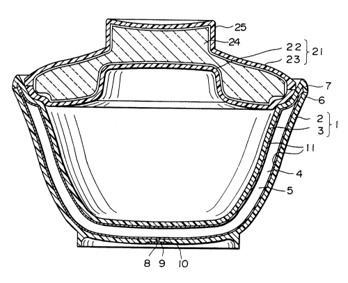
resin container comprises a container 1 and a lid 21 which
covers the mouth at the upper portion thereof.
The container 1 of this first example is formed from an
outer contA;ner 2 and an inner container 3, having a bowl-shaped
double wall structure with a thermal insulator layer 5 sealed
with low thermal conductivity gas in the space portion 4 between
the inner and outer containers. These inner and outer
cont~iners 2, 3 are formed from chemical-resistant and hot-
water-resistant synthetic resins by means of extrusion molding
or blow molding. Since the resin used is chemical-resistant,
there is no concern that cracks could be formed in container 1
after molding, such as by putting things in or by washing with
detergent, so that the strength of the container 1 can be
maintained. As used above, chemical-resistance refers to the
property of not being damaged, such as by forming cracks, even
under contact with chemicals such as organic solvents, bleaches
or detergents.
A depression portion 10 which is depressed in the direction
of the thermal insulator layer 5 is formed in the bottom center
of the outer container 2, and a hole portion 8 is drilled into
the central portion of this depression portion 10. A sealing
panel 9 is inserted and affixed within the depression portion 10
so as to seal off the hole portion 8. Like the inner and outer
cont~;ners 2, 3, this sealing panel 9 is also formed from a
chemical and hot-water resistant synthetic resin, and this
sealing panel 9 is affixed to the depression portion 10 by means
of adhesives in an airtight fashion. Because this sealing panel
9 is formed from a chemical resistant synthetic resin, there is
no concern that cracks could form in this sealing panel 9 due to
218~298
28
solvents contained in the adhesive, even if an adhesive is used
to seal the hole portion 8 with the sealing panel 9 after the
space portion 4 is filled with low thermal conductivity gas
through this hole portion 8. Additionally, cracks will not form
in the sealing panel 9 due to detergents either.
As the adhesive used to seal the sealing panel 9, a cyano-
acrylate adhesive can be used. These adhesives are highly
airtight after hardening, and allows the low thermal
conductivity gas filled into the space portion 4 of the
container 1 to be sealed because they allow a strong adhesive
force to be obtained immediately.
As the low thermal conductivity gas to be sealed into the
space portion 4 of the cont~; ner 1, at least one type of gas
chosen from among xenon, krypton and argon is used. The thermal
conductivities of these gases, xenon (K = O . 52 x 10-2 W m-l K-l; 0
C), krypton (K = 0.87 x 10⁻² W m-l R-l; 0 C) and argon (K = 1.63
x 10-2 W m-l-R-l; 0 C), are lower than that of air (K = 2.41 x
10-2 W-m-l R-l; 0 C), and these gases are sealed at a sealing
pressure of about atmospheric pressure either singly or as a
combined gas of two or more types. The thermally insulating
capabilities of the container 1 can be increased by using these
low thermal conductivity gases. Additionally, these low thermal
conductivity gases are inert, so that their use is favorable for
the environment.
The outer container end portion 6 and the inner container
end portion 7 are connected by a vibration welding method or a
spin welding method, thereby forming the space portion 4. With
a vibration welding method or a spin welding method, the portion
of attachment of the inner and outer containers 2, 3 can easily
218~298
_ ~ 29
and reliably be made into an airtight structure, while also
increasing the strength of attachment.
For the extrusion molding of the outer container 2 and the
inner cont~i ner 3, a mixed resin of polycarbonate and polyester
is used as chemical resistant resins. This mixed resin should
preferably be a blend of polycarbonate and polyester is a
mixture weight ratio of 7:3. This mixed resin has a chemical
resistance property of not changing even when coming into
contact with chemicals such as organic solvents, bleaches and
detergents, so that cracks (solvent cracks) will not be caused
by solvents in the coating material even when an ABS resin-type
coating is applied to the outer surface of the inner container 3
or the inner surface of the outer container 2 in order to allow
for the formation of a plating film. Additionally, there is no
concern of cracks forming on the inner surface of the inner
container 3 or the outer surface of the outer container 2 after
formation of the container 1 due to the contents or washing with
detergents. Additionally, this mixed resin is hot-water
resistant, and has much better gas barrier properties than
polycarbonates. Therefore, the possibility of the above-
mentioned low thermal conductivity gas filled into the space
portion 4 permeating the container wall and escaping is
extremely low. For this reason, there is not need to form a
plating film on the surfaces which face the space portion 4 of
the inner and outer containers 2, 3 in order to increase the gas
barrier capabilities if the product lifetime is allowed to be
short. The polyester contains polyethylene terephthalate or
polybutylene terephthalate.
Among the surfaces which face the space portion 4 formed
2185298
_ ~ 30
between the outer container 2 and the inner container 3, at
least the surface of the inner container 3 has radiation
prevention material 11 formed from metallic foil. As a metallic
foil, it is possible to use aluminum foil, copper foil, silver
foil or the like. These foils are attached by adhesives or
double-sided tape, and serve to suppress radiative heat loss
through the space portion 4.
The radiation prevention material 11 can be formed from a
plating film instead of a metallic foil. A copper plating or a
silver plating can be used as the plating, with the plating film
attached by electroplating on top of a chemical plating. As a
result, the radiative heat loss from the container 1 can be
suppressed, and the gas-barrier properties of the inner and
outer containers is increased. As mentioned above, the
polycarbonate and polyester mixed resin has excellent gas-
barrier properties, so that the partial failure of the plating
film to stick, which has conventionally been regarded as a flaw,
can be allowed to some extent, thereby decreasing the rejection
rate of the plating. Consequently, it is possible to lower the
manufacturing costs.
On the above-mentioned mixed resins wherein plating films
cannot be formed directly on the container walls facing the
space portions of the inner and outer containers 2, 3, an ABS
resin-type coating is applied to only the surface on which the
plating film is to be formed, then a plating film is formed only
on the coated surface. The adherence of the plating film to the
coating surface of ABS resin-type coating material is improved,
so that a precise plating film can be formed by only applying
coatings to the surfaces aside from the hole portion 8 and the
21~298
31
àttachment portion between the inner container end portion 7 and
the outer container end portion 6.
A lid 21 is detachably fitted with the mouth of the
cont~;ner 1 formed in this way. The lid 21 is formed from a
bottom wall 22 and a top wall 23, with a thermal insulator
material 24 formed from styrofoam, urethane or the like provided
in the space formed between the top and bottom walls, and the
end portions of the bottom wall 22 and the top wall 23 being
formed so as to connect. A protrusion which acts as a handle 25
is formed on the top wall 23. The heat preserving effects of
the cont~;ner 1 are able to be increased by covering the
cont~;ner 1 with this type of lid 21.
Instead of the ther~l insulator material 24 of this lid
21, it is also possible to use the same thermally insulating
structure as the thermal insulator layer 5 wherein the low
thermal conductivity gas is sealed into the container 1 as
mentioned above.
Next, the method of manufacturing the thermally insulated
double-walled synthetic resin container of the present invention
shown in Fig. 1 will be explained.
A chemical resistant resin is used to mold the inner
container 3 and the outer container 2 when the container 1 is
manufactured. A mixed resin of polycarbonate and polyester is
suitable for use as a chemical resistant resin.
2~ sy forming the inner and outer containers 2, 3 from
chemical resistant resins, cracks will not form in the inner and
outer container due to the contents of the container 1 or by
washing with detergent, and the strength of the inner and outer
containers can be maintained. Additionally, if the resins used
~18~298
_ ~ 32
to form the inner and outer containers are resins on which it is
difficult to form plating films, then the solvents contained in
the coating when an ABS resin-type coating is applied in order
to form a radiation prevention material by a plating film on
this resin will not cause cracks in the coated surface.
Thereafter, a radiation prevention material 11 composed of
a metal is formed on at least the surface of the inner container
3 among the surfaces of the inner container 3 and the outer
container 2 which face the space portion 4. In order to form
radiation prevention materials 11 on these surfaces, either a
method wherein a metallic foil such as aluminum foil, copper
foil or silver foil is adhesively affixed by means of an
adhesive or double-sided tape, or a method wherein copper or
silver is plated by means of chemical plating or electroplating
is used. When the metallic plating is to be formed by means of
electroplating, an ABS resin-type coating is applied to the
surface portions to be plated; plating layers can be easily and
reliably formed by plating at these coated portions.
Next, the inner container 3 and the outer container 2 are
combined, and the inner container end portion 7 and the outer
container end portion 6 are attached by means of vibration
welding or spin welding, so as to form a double-walled container
having a space portion 4 between the inner and outer containers
2, 3.
Then, this double-walled container is overturned and the
air in the space portion 4 is exhausted from a hole portion 8 in
the outer container 2, after which the space portion 4 is filled
to approximately atmospheric pressure through the hole portion 8
with at least one type of low thermal conductivity gas selected
2185298
_ ~ 33
from among xenon, krypton and argon, then a cyano-acrylate type
adhesive is coated onto the hole portion 8 and the depression
portion 10 and a sealing panel 9 is immediately inserted into
the depression portion 10 so as to completely seal off the hole
portion 8 by adhesively affixing the sealing panel 9.
Consequently, a cont~;ner 1 with a double-walled structure
having high ther~lly insulative properties is produced.
The lid 21 is produced by making a top wall 23 and a bottom
wall 22 having a handle 25 using an appropriate synthetic resin,
filling the space therebetween with a thermal insulator 24 such
as polys~lofoam or urethane, then attaching the end portions of
the top wall 23 and the bottom wall 22. During the manufacture
of the lid 21, the interior may be filled with a low thermal
conductivity gas instead of the thermal insulator 24 by applying
the manufacturing method of container 1; in this case, the
thickness of the thermally insulating space layer can be made
small so as to make the lid 21 more compact.
Figs. 2 and 3 show a second example of the thermally
insulated double-walled synthetic resin container of the present
invention; Fig. 2 shows the entire container, and Fig. 3 shows
the bottom central portion of the outer container. This
thermally insulated synthetic resin container is composed of a
container 31 and a lid 51 covering the mouth portion of the
container 31.
This container 31 is composed of an outer container 32 and
an inner container 33 formed by extrusion molding with a hot-
water resistant polycarbonate resin, polypropylene resin, ABS
resin, polyester resin or the like, and is a bowl-shaped
container having a double-walled structure with a thermal
~~ ~ 1 83542 9 8
insulator layer 35 at the space portion 34 between the inner and
outer containers.
A protrusion portion 41 is formed at the center of the
outer contA;ner bottom portion 38 on the thermal insulator layer
35 side, and a depression portion 40 aligned with the center of
the protrusion portion 41 is formed on the surface by making the
bottom wall of the outer container 32 protrude into the thermal
insulator layer 35 side. The thickness of the outer container
bottom portion 38 with the formation of the protrusion portion
41 and the depression portion 40 is formed so that the thickness
of the bottom wall becomes approximately uniform. By making the
thickness of the central portion of the outer container bottom
portion 38 approximately equal to the thickness at the other
portions, the strength of the central portion of the outer
contAi ner bottom portion 38 can be maintained, especially
effective in the case of a contA;n~r formed from a double-walled
container in which the thickness of the inner and outer
containers must be made small in comparison to cooler boxes and
heat preserving lunchboxes.
The above-mentioned depression portion 40 is for adhesively
fitting the sealing panel 39, and the depth of the depression
portion 40 is made the same as the thickness of the sealing
panel 39, which is formed from the same resin as the inner and
outer containers. Due to this type of structure, the bottom
portion of the container can be made smooth when the container
31 is assembled, giving it an excellent- outward appearance.
At the center of the outer container bottom portion 38,
i.e. at the center of the depression portion 40, a hole portion
42 which connects the interior and exterior of the outer
" , 218~298
-
`container bottom portion 38 is formed. This hole portion 42 is
for replacing and sealing with low thermal conductivity gas
after the inner and outer containers have been connected to form
a double-walled contA;ner during the manufacturing process of
the container 31. The hole portion 42 is sealed off with
adhesives after filling. The diameter of this hole portion 42
should preferably be 0.1 - 3 mm so that the adhesive will not
drip down during the sealing process.
The outer cont~;ner 32 and the inner container 33 are
attached at their respective end portions 36, 37 to form a
double-walled cont~in~r by means of a vibration welding method
or a spin welding method. The degree of sealing and the
strength of attachment at the portions of attachment of the
inner and outer cont~;ners are made high because the inner and
outer cont~;ners are attached by means of vibration~welding or
spin welding.
The thermal insulator layer formed between the inner
container and the outer container is filled with at least one
type of low thermal conductivity gas selected from among xenon,
krypton and argon. These may be used singly or as mixed gases
of two or more types. A cont~iner with exceptional thermal
insulation capabilities is able to be obtained by using these
low thermal conductivity gases.
As shown in Fig. 3, the hole portion 42 of the outer
container bottom portion 38 is formed such that the diameter
becomes smaller from the bottom surface depression portion 40
side of the outer container 32 towards the protrusion portion 41
side of the thermal insulator space. In this case, the hole
diameter on the protrusion portion 41 side is preferably 0.1 - 3
~1852g8
_ 36
~m, and more preferably 0.5 - 2.5 mm; the hole diameter on the
depression portion 40 side is preferably 2 - 5 mm, more
preferably 3 - 4 mm. As will be explained below, the double-
walled container is overturned, filled with low thermal
conductivity gas, and the hole portion is immediately sealed
with adhesives during the manufacturing process for the double-
walled container. At that time, if diameter of the hole portion
decreases in the direction of the thermal insulator layer, the
hole portion 42 acts as a funnel so that even if drops of
adhesive are dripped from above, the diameter of the hole
portion is wide on the depression portion 40 side, thereby
making it easy to catch the drops of adhesive and allowing the
hole portion to be easily sealed with adhesive. Additionally,
the hole diameter on the protrusion portion side is small at 0.1
- 3 mm, so that the surface tension of the adhesive works to
prevent dripping.
The above-mentioned hole portion 42 is sealed by means of
cyano-acrylate type adhesives. These adhesives are highly
impenetrable to gases and are able to confer gas barrier
properties to the adhesive portion 49. They also offer
immediate and powerful adhesive strength, so that they can
effectively seal off the low thermal conductivity gas filled
into the space portion 34 of the double-walled container.
A sealing panel 39 is fitted and adhered to the depression
portion 40 of the outer container 32. That is, after the hole
portion 42 is sealed off by adhesives, the sealing panel 39 is
coated with cyano-acrylate type adhesives and fitted into the
depression portion 40 of the outer container 32, whereby the
adhesive portion 49 is protected from external objects.
218~298
_ 37
Additionally, since the sealing panel 39 is fitted and adhered
to the depression portion 40, the position of the sealing panel
39 is easily decided during manufacture of the double-walled
cont~;ner, so that there are no changes in the position of the
sealing panel 39.
A metallic radiation prevention material 48 is provided on
the surface of at least the inner container 33 among the rear
surfaces of the inner container 33 and the outer container 32
which face the space portion 34; these suppress radiative heat
loss from the thermally insulated double-walled synthetic resin
cont~; ner. The radiative heat loss can be made even smaller by
providing radiation prevention materials on the inner surface of
the outer cont~; ner as well.
As the radiation prevention material 48, one type selected
from among a plating film, aluminum foil, copper foil and silver
foil is used. The foils such as aluminum foil, copper foil and
silver foil may be attached by means of adhesives or double-
sided tape, and are able to be attached cheaply and easily.
Additionally, the plating film is formed by electroplating on
top of a chemical plating. In addition to reducing the
radiative heat loss, the plating film offers the advantage of
increasing the gas barrier properties.
The mouth portion of the container 31 formed in this way is
covered by a lid 51 which is capable of engaging with an
interior portion of the container mouth. The lid 51 is formed
from a top wall 52 and a bottom wall 53, with a thermal
insulator material 54 formed from styrofoam, urethane, or the
like being formed in the space between the top and bottom walls,
which are attached so as to have an airtight structure.
2185298
-_ 38
Additionally, a protrusion portion functioning as a handle 55 is
formed on the top wall 53. The heat preserving effect of the
cont~i ner 31 can be increased by covering the container 31 with
this type of lid 51.
Next, the method for producing the thermally insulated
double-walled synthetic resin container according to the second
example of the present invention will be explained with
reference to Figs. 4 and 5.
Fig. 4 shows a mold for extrusion molding the outer
cont~; ner,
As shown in Fig. 4, a male mold 45 for forming the inner
surface of the outer container 32 and a female mold 43 for
forming the outer surface of the outer container 32 are used to
form a extrusion molding space portion 47 as explained below.
First, a mold depression portion 45a is formed at a
corresponding position on the extrusion molding surface of the
male mold 45 in order to make the protrusion portion 41 of the
outer container 32. Additionally, a mold protrusion portion 43a
is formed at a corresponding position on the extrusion molding
surface of the female mold 43 in order to make the depression
portion 40 of the outer container 32. Also, a hole-opening
protrusion portion 44 is formed at the center of the mold
protrusion portion 43a of the female mold 43 in order to pass
through the bottom wall of the outer container 32 to form a hole
portion 42 at the center of the bottom wall. This hole-opening
protrusion portion 44 is formed so as to be longer than the
thickness of the bottom wall in the vicinity of the hole portion
42 of the outer container 32, and has a diameter which becomes
shorter from the base portion 44a to the tip portion 44b.
218~2g8
_ 39
Additionally, an extrusion molding gate 46 having a
diameter larger than the diameter of the hole-opening protrusion
portion 44 of the female mold 43 is provided at a central
position of the mold depression portion 45a of the male mold 45.
The extrusion molding space portion 47 is formed by inserting
the tip of the hole-opening protrusion portion 44 of the female
mold 43 into this extrusion molding gate 46, and bringing the
contact surfaces (not shown in the drawings) of the male mold 45
and the female ld 43 into contact.
The extrusion molding space portion 47 between the male
mold 45, the mold depression portion 45a and the mold protrusion
portion 43a is for forming the central portion of the outer
container bottom portion 38. In order to make the thickness of
the entire outer cont~; ner bottom portion 38 constant, the
thickness of the space portion is made uniform.
Next, as shown in Fig. 5, the outer container 32 is formed
by supplying synthetic resin through the extrusion molding gate
46 into the extrusion molding space portion 47. Then, the hole
portion 42 is formed on the outer container bottom portion 38 by
gate-cutting the gate pin 50 attached to the molded outer
container 32 due to the extrusion molding gate 46, thereby
completing the outer cont~; ner 32.
In this way, the outer container molding method described
above makes it unnecessary to perform special hole opening
procedures in order to form the hole portion.
Additionally, the extrusion molding gate 46 is provided at
the central position of the male mold 45 side, i.e. at the
central position of the mold depression portion 46 on the
extrusion molding surface of the male mold 45, so that when
2185298
`forming an outer container 32 with right/left symmetry, the flow
of synthetic resin into the extrusion molding space portion 47
is made even, thereby markedly reducing the occurrence of bad
welds, defects in appearance such as decentralization and
warping, and insufficient strength.
Further~ore, the gate cutting position is on the inner
surface side of the outer cont~;ner, so that the gate cutting
portion cannot be seen from outside when the outer container 32
is assembled with the inner container 33, which is favorable in
terms of the outer appearance. Additionally, a protrusion
portion 41 is formed on the thermal insulator layer side, so
that it is raised above other parts of the outer container
bottom portion 38 to allow an easy gate cutting procedure.
On the other hand, there are not especially any problems in
molding the inner cont~;ner 33, as long as the extrusion molding
gate is provided at the center of the bottom portion of the
outer surface of the inner container 33.
As explained above, a radiation prevention material 48
composed of metal is formed on the inner surface of the outer
cont~;ner 32 and the outer surface of the inner container 33
after the outer container 32 and the inner container 33 are
formed. The radiation prevention material 48 is formed either
by electroplating on top of a chemical plating by means of
copper, silver or the like, or adhering one type of foil
selected from among aluminum foil, copper foil and silver foil
by means of adhesives or double-sided tape. Then, the double-
walled container is formed by attaching the outer container 32
and the inner container 33 by vibration welding or spin welding
their respective end portions 36, 37.
" ~18S298
_ 41
Subsequently, this double-walled container is overturned,
and after filling the space portion 34 between the inner and
outer containers with at least one type of gas selected from
among xenon, krypton and argon, the hole portion 42 is sealed
off by a cyano-acrylate type adhesive while the double-walled
container is still overturned.
As explained above, the hole-opening protrusion portion 44
of the female mold 43 for forming the hole portion 42 of the
outer container 32 is shaped so that the diameter becomes
smaller from the base portion 44a in the direction of the tip
portion 44b, and is provided on top of the mold protrusion
portion 43a. Consequently, the hole portion 42 of the outer
container 32 has a structure wherein the diameter shortens from
the depression portion 40 side of the outer surface in the
direction of the protrusion portion 41 side of the inner
surface. Therefore, the hole diameter is wide on the depression
portion 40 side so that adhesives are easily drawn into the hole
portion 42 even if adhesives are dripped into the hole portion
42, and the hole portion sealing procedure is made easy. With
regard to the hole portion, when the hole diameter on the
protrusion 41 side is 0.1 - 3 mm, the hole diameter on the
depression portion 40 side should preferably be 3 ~ 5 mm, and
when the hole diameter on the protrusion portion 40 side is 0.1
- 1 mm, the hole diameter on the depression portion 40 side
should preferably be 3 - 4 mm.
The container 31 obtained in this way has exceptional
thermal insulation properties, as well as being excellent with
regard to strength and outward appearance.
Fig. 6 shows a third example of a container and a lid for
2185298
_ 42
the container according to the present invention, wherein
reference numeral 61 denotes a container and reference numeral
81 denotes a lid for covering this container 61.
This cont~;ner 61 is composed of an outer container 62 and
an inner cont~;ner 63, and is in the shape of a bowl with a
double-walled structure such that a space portion 64 between the
inner and outer cont~;ners is filled with low thermal
conductivity gas to form a thermal insulator layer 65. The
outer cont~;n~r 62 and the inner container 63 are formed by
extrusion molding or blow molding with synthetic resins such as
hot-water resistant polycarbonate resin, polypropylene resin,
ABS resin, polyester resin, and mixed resins of polycarbonate
and polyester as the raw material.
As shown in Figs. 6 and 7, this third example has metallic
foil 72 as a metallic film layer formed on the surfaces which
face the thermal insulator layer 65, except for the parts a and
b near the mouth of the inner container 63. Parts a and b are
not provided with metallic foil 72, so that the synthetic resin
of the inner and outer containers is exposed. This metallic
foil 72 is adhered to the outer surface of the inner container
63 and the inner surface of the outer container 62 by means of
adhesives or double-sided tape. The heat loss due to thermal
conductivity near the mouth portion 75 is largely reduced
because part a, which is the portion contacting the peripheral
portion 90 of the lid 81, and part b, which is the area around
the inner cont~;ner end portion 67, do not have metallic foil so
that the metallic foil 72 does not come into contact near the
mouth portion 75 of the container 61. Additionally, the
metallic foil 72 which is formed on most of the surface which
21852~8
~_ 43
faces the thermal insulator layer 65 allows the heat loss due to
radiation to be reduced when the container 61 is filled. Since
this metallic foil 72 does not require the use of any special
apparatus when compared to the formation of a plating film as
the metallic film layer, the manufacturing costs of the
container 61 can be markedly lowered. The length of part a is
approximately 20 mm, and the length of part b is approximately 5
mm.
Additionally, when a metallic foil 72 is provided on the
outer surface of the inner container 63, the metallic foil on
the area around the mouth portion 75 near part a can be made so -
as not to maintain complete contact with the surface of the
inner cont~;ner 63, so as to have a slight space between the
inner container 63 and the metallic foil 72. This type of
structure is able to reduce the heat loss around the mouth
portion 75 of the inner container 72.
The outer container end portion 66 and the inner container
end portion 67 are connected by means of vibration welding or
spin welding to form a space portion 64. When the outer
container end portion 66 and the inner container end portion 67
are connected by means of vibration welding or spin welding,
these connecting portions can easily and reliably be connected
in an airtight fashion, so that the space portion 64 between the
inner and outer containers is given an airtight structure and
the connective strength is increased.
The low thermal conductivity gas to be filled into the
space portion 64 of the container 61 can be selected from the
group consisting of xenon, krypton and argon. These gases can
be used singly or as a mixture of two or more types, which are
~18S298
_ ~ 44
filled into the space portion 64 at a pressure of approximately
atmospheric pressure. The thermal insulation capabilities of
the container 61 can be increased by using these low thermal
conductivity gases. Additionally, these low thermal
conductivity gases are inert, so that they are preferable for
use because they do not present a problem with regard to
protection of the environment.
Copper foil or aluminum foil can be used as the metallic
foil 72. These metallic foils are able to be obtained cheaply,
and are easily attached.
A depression portion 70 which is depressed toward the
thermal insulator layer 65 is formed in the bottom center of the
outer cont~i ner 62, and a hole portion 68 is drilled into the
central portion of this depression portion 70. This hole
portion 68 is sealed by inserting and affixing a sealing panel
69 into this depression portion 70. This sealing panel 69 is
affixed to the depression portion 70 in an airtight fashion by
means of adhesives. A cyano-acrylate type adhesive is used as
the adhesive for sealing the sealing panel 69. This adhesive is
extremely airtight after solidification and immediately applies
a strong adhesive force, so that the low thermal conductivity
gas can be sealed off after filling the space portion of the
container 61.
Fig. 8 shows a second example for the arrangement of the
metallic film layer on the container 61 illustrated in Fig. 6.
As shown in Fig. 8, this example has a structure such that a 1 ~
10 ~m thick copper plating film 73 which is thinner than the
metallic foil 72 is formed at parts a and b near the mouth
portion of the container 61. The thickness of this copper
2185298
_ ~ 45
plating film 73 is not thick enough the influence the heat loss
due to thermal conduction through the area around the mouth
portion of the inner container 63. This copper plating film 73
provides a gas-barrier property to parts a and b near the mouth
portion, and is able to reduce radiative heat loss. This copper
plating film 73 is formed by applying a glossy electroplating
film onto a foundation which is a chemical plating film. A
copper plating film is able to be formed cheaply in comparison
to a silver plating film, but is able to obtain the same
properties as a silver plating film.
Figs. 11 and 12 show a third example of the arrangement of
a metallic film layer on the container 61 illustrated in Fig. 6.
As shown in Figs. 11 and 12, this example is such that the
surfaces which face the thermal insulator layer 65 of the
cont~; ner 61 aside from the parts a and b near the mouth portion
are covered with a metallic coating 71 of copper plating film or
silver plating film as a metallic film layer for providing gas-
barrier properties. Forming this metallic coating 71 allows the
gas-barrier properties of the container 61 to be increased, as
well as to reduce the heat loss due to radiation. In this case,
the heat loss due to thermal conduction from the area around the
mouth portion can be reduced because the metallic film 71 is not
formed near the mouth portion 75.
Fig. 13 shows a fourth example of the arrangement of a
metallic film layer on the container 61 illustrated in Fig. 6.
As shown in Fig. 13, this example has à structure such that a 1
~ 10 ~m thick copper plating film 71a which is thinner than the
metallic coating 71 formed at parts other than the areas near
the mouth portion 75 is formed at parts a and b near the mouth
~185298
_ ~ 46
portion of the surfaces which face the thermal insulator layer
65 of the container 61 in order to provide gas-barrier
capabilities, and a 10 - 50 ~m thick metallic coating 71 is
formed on the other surfaces which face the thermal insulator
layer 65. The lower limit value for the thickness of the copper
plating film 71a formed at the surface of parts a and b is made
1 ~m because if the film is less than 1 ~m thick, then the
plating can crack under the influence of the heat of the
contents during use, as a result of which the gas-barrier
property is not able to be obtained. The upper limit value is
10 ~m because if the copper plating film 71a is made thicker
than 10 ~m, then there is a large loss due to thermal conduction
from the area around the mouth portion. While a metallic
coating 71 and a copper plating film 7la are formed so as to
cover the entire surface of the container which faces the
therm~l insulator layer 65, the thickness of the copper plating
film 71a near the mouth portion is made thin, so that the heat
loss due to thermal conduction from the area around the mouth
portion 75 is reduced. This is because the heat loss due to
thermal conduction of the metallic film which has a higher
thermal conductivity than the synthetic resin depends on the
thickness of the copper plating film 71a around the mouth
portion 75 of the inner container 63 when the contents are put
into the container 61. By making the thickness of the film at
parts a and b of the inner container 63 among the surfaces which
face the thermal insulator layer 65 thinner than the film at
other parts, the heat loss due to thermal conduction from the
container 61 is reduced when the contents are put in.
When a copper plating film is used as the metallic coating
2185238
_ 47
71, the portions of the outer surface of the inner container 63
and the inner surface of the outer container 62 aside from the
area around the mouth portion 75 of the inner container 63 have
a thickness of 10 - 50 ~m. The lower limit value for the film
thickness at parts of the inner container 63 other than the area
around the mouth portion 75 is 10 ~m because the plating can be
coated uniformly if the film thickness is 10 ~m or more, so as
to allow a completely gas-impenetrable plating film to be formed
on almost the entire surface of the container 61 facing the
thermal insulator layer 65. The upper limit value is 50 ~m
because a film thickness of 50 ~m is the limit with regard to
the production costs for plating formation even when considering
the unevenness of the plating film.
The above-mentioned inner and outer containers 62, 63
should preferably be formed by extrusion molding or blow molding
using chemical resistant and hot-water resistant synthetic
resins. In this case, chemical resistance refers to the
property of being stable with respect to solvent, bleaches and
detergents. By forming the inner and outer containers 62, 63 by
using chemical resistant and hot-water resistant synthetic
resins, damage such as by cracks does not occur to the container
61 even if the container 61 is filled or the container 61 is
washed with detergent, so as to allow the strength of the
container 61 to be maintained.
The sealing panel 69 which is inserted into the depression
portion 70 formed in the bottom center of the outer container 62
of the container 61 and affixed in an airtight fashion by means
of adhesives should preferably be formed from a chemical
resistant and hot-water resistant synthetic resin as with the
- '~185298
_ 48
inner and outer containers 62, 63. If the sealing panel 69 is
formed from a chemical resistant synthetic resin, then even if
the hole portion 68 is sealed with the sealing panel 69 using an
adhesive after the space portion 64 is filled with low thermal
conductivity gas through the hole portion 68, the solvents
contained in the adhesives will not cause damage such as cracks
to the sealing panel 69. Additionally, bleaches and detergents
will also not cause cracks to occur in the sealing panel 69.
For the extrusion molding of the inner container 62 and the
outer container 63, a mixed resin of polycarbonate and polyester
should preferably be used as the chemical resistant resin.
Specifically, a blend of polycarbonate and polyester in a mixing
weight ratio of approximately 7:3 is especially desirable. Even
if an ABS resin-type coating is applied for plating, the
solvents in the coating will not cause cracks (solvent cracks)
to occur, since this mixed resin is chemical resistant.
Additionally, cracks will almost never form on the inner surface
of the inner container 63 or the outer surface of the outer
container 62 after the container 61 has been formed, even if it
is filled with contents or washed with bleach or detergent.
Additionally, this mixed resin is hot-water resistant, and its
gas-barrier characteristics are several levels better than
polycarbonate resin, polypropylene resin or ABS resin.
Consequently, the probability of the low thermal conductivity
gas filled into the space portion 64 escaping outside of the
container through the container walls is extremely low. For
this reason, the gas-barrier capabilities can be made to
approach perfection by applying the metallic coating 71 to the
inner surface of the outer container 62 and the outer surface of
2185298
_ 49
the inner cont~;ner 63 facing the thermal insulator layer 65.
Additionally, if the product lifetime is allowed to be short,
then there is no need to form a metallic coating 71 on the
surfaces of the inner and outer containers 62, 63 which face the
space portion 64 in order to increase the gas-barrier
properties, and a container 61 with high thermal insulator
capabilities can be obtained by attaching metallic foil 72 to
the surfaces of the inner and outer containers 62, 63 which face
the thermal insulator layer 65 other than the areas near the
mouth portion 75 of the inner container 63. The polyester resin
in the mixed resin contains polyethylene terephthalate and
polybutylene terephthalate.
The thickness of the space portion 64 between the outer
container 62 and the inner container 63 of the cont~iner 61 is
set to within the range of 1 ~ 10 mm. If the thickness is
greater than 10 mm, then the heat loss due to thermal convection
of the low thermal conductivity gas filling the space portion 64
becomes large, so that the total amount of heat transferred in
the thickness direction of the space portion 64 increases,
thereby degrading the thermal insulation efficiency, and the
effective capacity of the container 61 is lessened due to the
space portion 64 becoming thicker. Additionally, if the
thickness is less than 1 mm, then it becomes difficult to form
the container 61 in a double-walled structure without accidental
contact between the outer container 62 and the inner container
63, so that a lot of care is required in production and the
production costs rise. The thickness of the space portion 64
can be made thin within the range of 1 - 10 mm, because the low
thermal conductivity gas is sealed into the space portion 64.
2185298
~ 50
,
Next, the lid of the container according to the present
invention shown in Fig. 6 will be explained.
As shown in Fig. 6, the lid 81 for covering the container
61 is formed from a bottom wall 82 and a top wall 83, and has a
double-wall structured cap shape having a thermal insulator
layer 85 wherein low thermal conductivity gas is sealed into the
space portion 84 between these top and bottom walls. Then, a
protrusion portion 91 on the top wall 83 becomes the handle of
the lid 81. These top and bottom walls 82, 83 are formed by
extrusion molding or blow molding synthetic resins such as hot-
water resistant polycarbonate resin, polypropylene resin, ABS
resin, polyester resin, and mixed resins of polycarbonate and
polyester.
As shown in Figs. 6 and 9, a metallic foil 91 is formed as
a metallic film layer on the portions of the surfaces which face
the thermal insulator layer 85 of the lid 81 except for the
parts c near the peripheral portion 90. ThiS metallic foil 91
is adhered to the inner surface of the top wall 83 and the outer
surface of the bottom wall 82 by means of adhesives or double-
sided tape. As a result, no metallic foil 91 is formed on thepart c which contacts the container 1, so that there is no
contact between the metallic foil 91 near the peripheral portion
90 of the lid 81, thereby markedly reducing the heat loss due to
thermal conduction from the bottom surface peripheral portion 90
of the lid 81. Additionally, since metallic foil 91 is formed
on most of the surfaces which face the`thermal insulator layer
85, the heat loss due to radiation leaks can be reduced.
The bottom wall end portion 88 and the top wall end portion
89 are attached by means of vibration welding or spin welding,
~18S298
51
.~
~hereby forming the space portion 84.
As a low thermal conductivity gas for filling the space
portion 84 of the lid 81, at least one type of gas is selected
from the group consisting of xenon, krypton and argon, similar
to the low thermal conductivity gas in the container 61.
Fig. 10 shows a second example for the arrangement of the
metallic film layer in the lid 81 illustrated in Fig. 6. As
shown in Fig. 10, this example has a 1 - 10 ~m thick copper
plating film 92 thinner than the metallic foil 91 formed in the
area around the peripheral portion 90 of the lid 80. The
thickness of this copper plating film 92 is not enough to
influence the heat loss due to thermal conduction from the area
around the peripheral portion 90 of the bottom wall 82, so that
part c in the area around the peripheral portion 90 of the
copper plating film 92 is given a gas-barrier property while
also reducing the heat loss due to radiation.
As this metallic film 91, a copper foil or an aluminum foil
is used. These metallic foils are cheaply available, and are
easily attached.
Figs. 11 and 14 show a third example for the arrangement of
the metallic film layer on the lid 81 illustrated in Fig. 6. As
shown in Figs. 11 and 14, this example has a metallic film 86
such as a copper plating film or a silver plating film as a
metallic film layer formed on the surfaces which face the
thermal insulator layer 85 of the lid 81 except for part c
around the peripheral portion 90 in order to give a gas-barrier
property, while the synthetic resin at part c is exposed. By
forming this metallic film 86, the gas-barrier property of the
lid 81 can be increased while reducing the heat loss due to
~1852~8
52
,
radiation. In this case, no metallic film layer is formed on
part c around the peripheral portion 90, so that the heat loss
due to thermal conduction from the peripheral portion 90 can be
reduced.
Fig. 15 shows a fourth example for the arrangement of the
metallic film layer on the lid 81 illustrated in Fig. 6. As
shown in Fig. 15, this example has a 1 - 10 ~m thick copper
plating film 86a thinner than the metallic foil 86, the metallic
film layer in the area around the peripheral portion 90 of the
surfaces which face the thermal insulator layer 85, formed on
part c in the area around the peripheral portion 90 of the
surfaces which face the thermal insulator layer 85 of the lid 81
in order to provide gas-barrier properties. The lower limit
value for the thickness of this copper plating film 86a is 1 ~m
because if the thickness is less than 1 ~m, then cracks can form
in the plating under the influence of heat from the contents
during use, as a result of which the gas-barrier property will
be lost. The upper limit value is 10 ~m because if the
thickness of the copper plating film 86a is greater than 10 ~m,
then the heat loss due to thermal conduction from the area
around the peripheral portion 90 becomes large. While the
structure shown in Fig. 15 has a metallic film 86 and a copper
plating film 86a covering the entire surface which faces the
thermal insulator layer 85 of the lid 81, the heat loss due
thermal conduction from the area around the peripheral portion
90 is held low because the film is thin around the peripheral
portion 90. This is because the heat loss due to thermal
conduction from the metallic film 86, which has a higher thermal
conductivity than the synthetic resin, depends upon the
2185298
~ 53
. ~
thickness of the copper plating film 86a around the peripheral
portion 90 of the lid 81, so that the heat loss due to thermal
conduction from the lid 81 can be made smaller by forming the
film at part c around the peripheral portion 90 of the surfaces
facing the therr-l insulator layer 85 thinner than the thickness
at other parts.
A hole portion, not shown in the drawings, which connects
to the space portion 84 is provided on the lid 81, and this hole
portion is sealed in airtight fashion by means of a sealing
panel which is not shown in the drawings. This sealing panel is
attached and affixed after low thermal conductivity gas has been
introduced into the space portion 84 through the hole portion,
by adhering the sealing panel by means of a cyano-acrylate type
adhesive to seal off the hole portion. Additionally, the bottom
wall 82 and the top wall 83 of this lid 81 can be formed from a
chemical resistant and hot-water resistant synthetic resin as
with cont~;ner 61, such as a mixed resin of polycarbonate and
polyester. By forming the lid 81 from a chemical resistant
synthetic resin material, cracks (solvent cracks) due to
solvents in the coating will not form even if an ABS resin type
coating is applied for plating. Additionally, after the lid 81
is formed, contents can be put in and bleaches or detergents can
be used for washing without causing cracks to form on the inner
surface of the bottom wall 82 or the outer surface of the top
wall 83. Furthermore, this mixed resin is hot-water resistant,
and offers gas-barrier capabilities which are superior to
polycarbonate resin, polypropylene resin and ABS resin.
Therefore, the probability of the low thermal conductivity gas
filled into the space portion 84 escaping by means of permeation
218S298
54
~hrough the container walls is extremely slight. Consequently,
the gas-barrier property can be made almost perfect by applying
a metallic film 86 on the outer surface of the bottom wall 82 or
the inner surface of the top wall 83 which face the thermal
insulator layer 85. Additionally, if the product lifetime is
allowed to be short, then there is no need to form a plating
film on the surfaces which face the space portion 84 between the
top and bottom walls 82, 83 in order to increase the gas-barrier
capabilities, so that a lid 81 with excellent thermal insulation
performance can be obtained by adhering a metallic foil 91 to
the surfaces which face the thermal insulator layer 85 of the
top and bottom walls 82, 83 aside from the peripheral portion 90
of the bottom wall 82.
The thickness of the space portion 84 between the top wall
82 and the bottom wall 83 of the lid 81 is set to within the
range of 1 - 10 mm. If this thickness is greater than 10 mm,
then when the lid 81 is formed, the heat loss due to-convective
thermal conduction of the low thermal conductivity gas inside
the space portion 84 becomes large, so that the total thermal
conduction in the thickness direction of the space portion 84
increases and the thermal insulation efficiency becomes worse.
Additionally, the space portion 84 becomes so thick that the lid
81 is made undesirably bulky. If this thickness is less than 1
mm, then it becomes difficult to form the lid 81 into a double-
walled structure while avoiding contact between the top wall 82and the bottom wall 83, so that undue care is required during
manufacture and the manufacturing costs rise. The thickness of
the space portion 84 can be made as thin as 1 ~ 10 mm largely
because the space portion 84 is filled with a low thermal
2185298
_ 55
conductivity gas.
Hereinbelow, other embodiments of the lid for the container
of the present invention will be explained with reference to
Figs. 16 through 20. As shown in Fig. 16, reference numeral 101
denotes a container having a lid, which is composed of a
contA;ner 103 and a lid 102.
The container 103 is composed of a inner container 103a and
an outer container 103b molded from hot-water resistant
polycarbonate resin, polypropylene resin, ABS resin or polyester
resin. After the inner container end portion 111 and the outer
container end portion 112 are attached by means of vibration
welding or spin welding, the space portion 119 formed between
the inner and outer containers is filled with at least one type
of gas chosen from among xenon, krypton and argon through a hole
portion (not shown in the drawings) formed in the outer
cont~; n~r 103b, then the hole portion is sealed off by means of
a sealing panel to which a cyano-acrylate type adhesive has been
applied. The container 103 is bowl-shaped, and a mouth
circumferential wall portion 108 which engages with the
peripheral portion 107 of the lid 102 is formed in the area
around the mouth portion 120 of the container 103.
The lid 102 of this container 101 has a bottom wall 102a
and a top wall 102b, and the top and bottom walls are formed
from hot-water resistant polycarbonate resin, polypropylene
resin, ABS resin or polyester resin, similar to that used for
the container 103. The top wall 102b has a cylindrical top wall
protrusion portion 105 which protrudes upwards formed at the
central portion, while the bottom wall 102a has a cylindrical
bottom wall protrusion portion 104 which protrudes upwards
2185298
_ 56
formed at the central portion so as to be supported in the space
portion 115. Additionally, the inner diameter of the bottom
wall protrusion portion 104 is slightly larger than the outer
diameter of the top wall protrusion portion 105. Furthermore,
the height of the bottom wall protrusion portion 104, without
considering the thickness of the bottom wall, is made
approximately equal to the height of the top wall protrusion
portion 105.
The lid 102 is obt~;ne~ by attaching the bottom wall end
portion 109 and the top wall end portion 110 by means of
vibration welding or spin welding in an airtight structure. As
a result, when lids 102 of this type are stacked on top of each
other, the top wall protrusion portion 104 of the bottom lids
can be inserted into the cylindrical space formed by the bottom
surface protrusion portions on the lids thereabove.
In this case, a top wall abdominal portion 117 having a
gradual downward slope from the base of the top wall protrusion
portion 110 is formed on the top wall 102b. Additionally, a
bottom wall abdo~;n~l portion 117 having a gradual downward
slope from the base of the bottom wall protrusion portion 104 is
formed on the bottom wall 102a. The downward slope of this
bottom wall abdominal portion 118 is formed so as to
approximately match the downward slope of the top wall abdominal
portion 117.
Consequently, the bottom wall abdominal portions 118 of the
upper lids easily fit with the top wall- abdominal portions 117
of the bottom lids when the lids are stacked.
Alternatively, the bottom wall abdominal portion 118 can be
made to bulge downward without matching the downward slopes of
~185298
_ 57
the bottom wall abdominal portion 118 and the top wall abdominal
portion 117. In this case, the bottom wall abdominal portion
118 is made to bulge uniformly over the circumferential
direction, so that the lids 102 sit well when they are stacked.
On the other hand, the circumferential wall portion 107 of
the bottom wall 102a is shaped with an upward curve, so that the
bottom wall end portion 109 of the circumferential portion 107
is able to connect with the top wall end portion 110 of the top
wall 102b. As a result, a space portion 115 is formed when the
bottom wall 102a and the top wall 102b are connected at their
respective end portion 109, 110. In this case, the space
portion 115 is filled with air, so as to obtain an air-insulated
lid 102.
The circumferential wall portion 107 of the bottom wall
102a is shaped so as to contact the surface of the mouth inner
circumference wall portion 108 of the container 103. As a
result, the circumferential wall portion 107 and the mouth inner
circumference wall portion 108 achieve contact at their
surfaces, so that the conductive distance between the exterior
and interior of the container 101 becomes large, thereby
allowing the thermal insulation effect of the lid 102 to be
increased and making it difficult for the heat from food to
escape from the container 103. Additionally, they are engaged
by contact at their surfaces, so that the setting of the lid
onto the container body is improved, thereby producing a
clicking sensation during application and improving the
stability for transport.
The width of the contact surface, that is, the width d
shown in Fig. 16, is at least 5 mm. This is because the effect
218S298
~ 58
of increasing the thermal insulation capabilities is not
sufficient when the width d is less than 5 mm.
Fig. 17 is an enlarged view of part A in Fig. 16. As shown
in Fig. 17, a notch 113 is formed in the radial direction of the
circumferential wall portion 107 of the lid 102. This notch 113
is formed so as to allow communication between the interior and
exterior of the cont~;ner 101 from the top wall end portion 110
to the circumferential wall portion 107. It is sufficient that
this notch be a semi-circle wherein the cross-sectional diameter
which orthogonally intersects the longitudinal direction of the
notch is approximately 3 mm, and the heat from food put into the
container 101 will not easily escape due to the formation of
this notch 113. Consequently, the lid 102 can always be removed
from the container 103 without the lid 102 sticking and becoming
difficult to remove, even if hot food is put into the container
103 and covered with the lid 102, then left until the
temperature of the food drops.
Additionally, the cross-sectional shape of the notch 113 is
arbitrary.
The thickness of the lid formed by the bottom wall 102a and
the top wall 102b, that is, the thicknesses e and f shown in
Fig. 16 are 10 - 15 mm. In this case, the area around the
circumferential wall portion 107 and the space portion between
the portions at which the top wall protrusion portion 105 and
the bottom wall protrusion portion 104 rise are made thinner
than other portions. However, since the thickness of almost all
of the portions of the lid 102 can be made 10 ~ 15 mm, the
thermal insulation space of the lid 102 can be made large so as
to improve the thermal insulation capabilities without degrading
~ ~185298
_ ~ 59
the outward appearance.
If these thicknesses e and f are less than 10 mm, then the
effect of increasing the thermal insulation capabilities is not
sufficient. Additionally, if these thicknesses e and f are made
greater than 15 mm, then the storage capacity of the container
101 becomes smaller than is preferable.
The shape of the top wall protrusion portion 105 as the
handle portion 106 of the lid 102 is made into a cylinder or a
polygonal cyl ;n~er. By making the top wall protrusion portion
105 of the lid 102 into a cylindrical shape as shown in Fig. 18,
the thickness of the lid 102 can be made larger by forming a
canopy portion 102c on the top wall protrusion portion 105. If
the top wall protrusion portion 105 of the lid 102 is formed
into a cylindrical shape, then the inner diameter of the bottom
wall protrusion portion 104 must be made slightly greater than
the outer diameter of the top wall protrusion portion 105. As
shown in Fig. 19, the thickness of the lid can be made greater
by forming a canopy portion in the case wherein the top wall
protrusion portion of the lid 102 is a polygonal cylinder as
well. In this case, the shape of the bottom wall protrusion
portion can be formed slightly larger with the same shape as the
top wall protrusion portion so as to allow the bottom wall
protrusion portions to be stored in the top wall protrusion
portions when the lids are to be stacked; however, the bottom
wall protrusion portion 104 should preferably have a cylindrical
shape with an inner diameter larger than the diameter of a
circle circumscribing the top wall protrusion portion so that
the top wall protrusion portion can be stored in the cylindrical
space of the bottom wall protrusion portion at any position
21~S298
., .
along the circumferential direction of the lids.
The designability of the lid can be increased by giving the
top wall protrusion portion a cylindrical or polygonal
cylindrical shape in this way.
The space portion 115 of the lid 102 can be made into a
thermal insulation layer 114 by filling with a thermal insulator
material selected from among styrofoam, urethane and pearlite
powder. Their respective thermal conductivities are styrofoam
(K = 3.50 x 10⁻² W m-1 R-1; 0 C), urethane (K = 1.75 x 10⁻² W-m-
1-R-1; 0 C) and pearlite powder ( K = 1 0 . 3 x 1 o-2 W m-1-R-1; 0
C), they are lightweight, and the thermal insulation
capabilities can be increased by suppressing thermal conductance
due to convection currents in the space portion 115 by filling
with these filler materials. The styrofoam and urethane are
filled by molding into a shape somewhat smaller than the space
portion 115. When styrofoam or urethane is used, the lid 102 is
obtained by placing the thermal insulator material onto the
bottom wall 102a or the top wall 102b, then stacking the top
wall 102b or bottom wall 102a thereon, and connecting the end
portions of the top and bottom walls by means of a vibration
welding method or a spin welding method in an airtight fashion.
The pearlite powder is filled into the lid 102 after the end
portions of the top and bottom walls have been connected by
means of a vibration welding method or a spin welding method in
an airtight fashion, by filling through a filling hole (not
shown in the drawings) and sealing with a sealing panel (not
shown in the drawings). Since styrofoam, urethane and pearlite
powder are cheap, the lid 102 can be cheaply made.
The space portion 115 of the lid 102 can also be filled
21~238
61
~ith at least one type of low thermal conductivity gas selected
from among xenon, krypton and argon. These can be used either
singly or as mixed gases of two or more. The lid 102 can be
given high thermal insulation capabilities by using these low
thermal conductivity gases, so as to approach the thermal
insulation capabilities of the container 103. Furthermore,
since they are inert, their use is not a problem in terms of
environmental protection and are highly suitable for use. These
gases are filled through a hole portion 121 as shown in Fig. 20,
then sealed by means of a sealing panel 122 of the same material
as the inner and outer walls of the lid using a cyano-acrylate
type adhesive.
When the space portion 115 is filled with a low thermal
conductivity gas such as xenon, krypton or argon, the thickness
of the lid e and f can be made 5 - 10 mm.
If the space portion 115 is filled with a low thermal
conductivity gas, it becomes lighter than thermal insulator
materials such as styrofoam, urethane and pearlite powder, and
the resulting lid 102 will not feel heavier. Additionally, in
this case, the gas-barrier capabilities of the top and bottom
wall of the lid will not be degraded to allow leaks of the
filled gas, since the top wall 102b and the bottom wall 102a of
the lid 102 are molded from chemical resistant and hot-water
resistant mixed resins wherein polycarbonate and polyester are
blended at a ratio of 7 : 3.
Additionally, a radiation prevention material 123 composed
of a metal is formed on at least the surface of the bottom wall
among the surfaces of the top and bottom wall forming the lid
which face the space portion 115. This allows radiative thermal
2185298
62
leakage from the lid 102 to be suppressed. Additionally, the
radiative thermal leakage can be markedly reduced by forming
radiation prevention materials 123 composed of metals on the top
wall 102b as well as the bottom wall 102a.
Furthermore, as the metal composing the radiation
prevention material 123, it is possible to select one from among
plating film, aluminum foil, copper foil and silver foil. A
plating film can be applied by electroplating on top of a
chemical plating. If the radiation prevention material 123 is
made a plating film, then the gas-barrier property can be
improved in addition to reducing the radiative thermal loss.
Foils such as aluminum foil can be attached to the surfaces of
the top and bottom walls forming the lid which face the space
portion by means of adhesives or double-sided tape. As a
result, the radiation prevention materials 123 can be attached
cheaply and easily.
Fig. 21 illustrates a vibration welder as an example of a
manufacturing apparatus suitable for carrying out the
manufacturing method for the thermally insulated double-walled
synthetic resin cont~;ner of the present invention. This
vibration welder 131 has a lower support stand 134 and an upper
support stand 132; the lower support stand 134 is anchored to a
base 136. The upper support stand 132 moves up and down by
means of the driving force of an air cylinder 138. This upper
support stand 132 is made so as not to be able to rotate
horizontally due to two guide rods 140, 140 connected to the
upper support stand 132 which move up and down along guides 139.
When the upper support stand 132 is lowered, convex portions of
upper positioning blocks 132a, 132a at both ends of the upper
~185298
_ ~ 63
support stand 132 engage with concave portions of lower
positioning blocks 134a, 134a on the lower support stand so as
to allow the upper support stand 132 to be positioned onto the
lower support stand 134.
A lower jig 135 is affixed to the lower support stand 134,
and an upper jig 133 is affixed to the upper support stand 132.
The lower jig 135 and the upper jig 133 should preferably be
unitarily molded from metals such as aluminum. A concave
portion 135c is formed in the lower jig 135, and a lower work
member 135b which supports almost the entire outer surface of
the outer container 151 of the double-walled container is
attached to this concave portion 135c. On the other hand, a
convex portion 133c is formed on the upper jig 133, and an upper
work member 133b which supports almost the entire inner surface
of the inner cont~; ner 152 of the double-walled container is
formed on this convex portion 133c. The lower work member 135b
and the upper work member 133b are formed from flexible urethane
rubber or the like, and are respectively affixed to the lower
jig 135 and the upper jig 133 by means of adhesives or the like.
Therefore, the lower work member 135b and the upper work member
133b are exchanged along with the lower jig 135 and the upper
jig 133. The center of the convex portion 133c of the upper jig
133 affixed to the upper support stand 132 moves vertically
along the axis connecting it with the center of the concave
portion 135c of the lower jib 135 by means of the driving force
of the air cylinder 138.
Figs. 22 and 23 illustrate the state wherein the lower jig
135 and the upper jig 133 have been attached to the vibration
welder 131, and the synthetic resin inner container 152 has been
2185298
` 64
put into the outer cont~;ner 151 and arranged on the vibration
welder 131, prior to welding.
As shown in these drawings, a ring-shaped groove 135a
concentric with the center of the concave portion 135c is formed
around the concave portion 135c on the lower jig 135 which
supports the outer container 151 through the lower work member
135b. Additionally, a ring-shaped groove 133a facing the groove
135a in the lower jig 135 is formed in the upper jig 133 which
opposes the lower jig 13S in the vertical direction. A
cylindrical rubber ring 137 having parallel and smooth ends to
fit with this groove 135a is affixed to this groove 135a.
Flexible silicone rubber is suited to use for this rubber ring
137. Additionally, this rubber ring 137 is adhesively attached
by means of a cyano-acrylate type adhesive such that the axial
direction of the rubber ring 137 is aligned with the drive
direction of the air cylin~er 138. Since cyano-acrylate type
adhesives are airtight and are strongly adhesive, they allow the
rubber ring 137 and the lower jig 135 to be held sufficiently
airtight. The rubber ring 137 can also be attached to the
groove 135a by means of mechanical fixation means such as
chucks.
When the upper jig 133 is lowered, the upper surface of the
rubber ring 137 contacts the groove 133a and the rubber ring 137
is compressed. The amount of compression is set to
approximately 0.1 - 2 mm, so that the downward movement of the
air cylinder 138 is controlled when the rubber ring 137 is
compressed. Since the lower surface of this rubber ring 137 is
attached, the rubber ring 137 will not come free from the groove
135a even if it is vibrated or bent due to compression when the
21658~298
ùpper jig 133 is lowered. As the upper jig 133 is lowered to
compress the rubber ring 137, a space 148 is able to be formed
between the outer cont~i ner 151 and the inner container 152 held
be~wecn the lower jig 135 and the upper jig 133. Instead of
using the cylindrical shape of the above example for this rubber
ring, it is possible to use an O-ring shape as well.
When the lowering of the upper jig 133 is stopped, a gap is
formed between the lower jig 135 and the upper jig 133, and a
gap 146 is formed between the lower work member 135b and the
upper work member 133b.
At least one of the upper jig 133 and the lower jig 135 is
made so as to be capable of vibrating by means of vibration
generating means not shown in the drawings. This vibration
generating means is provided on the upper support stand 132 or
the upper jig 133, and/or the lower support stand 134 or the
lower jig 135. As shown in Fig. 22, the upper jig 133 is
lowered so as to achieve contact between the outer container end
portion 151a and the inner container end portion 152a through
the projection 151b, and by vibrating the upper jig 133 and/or
the lower jig 135 by driving the vibration generating means, the
end portions are welded together by generating frictional heat
between the inner container end portion 152a and the outer
container end portion 151a. The vibrations applied to the upper
jig 133 can have a frequency of tens of Hz to tens of thousands
of Hz, preferably 50 - 150 Hz, and the amplitude should be a few
mm. The vibration generating means is not especially
restricted, so that a vibration generating cylinder or motor can
be used.
A gas filler/exhaust route 134b for filling and exhausting
`. . ~1852g8
66
the space 148 is formed in the lower jig 135 and the lower
support stand 134. This gas filler/exhaust route 134b is
connected to a gas filler/exhaust pipe 141, and to the end 141a
of this gas filler/exhaust pipe 141, a vacuum pump 142 is
connected via a valve 144, and a low thermal conductivity gas
filled container 143 is connected via the valve 145. These
allow the space 148 to be filled and exhausted through the gas
filler/exhaust route 134b and the gap 146. This gas
filler/exhaust route 134b is formed so as to pass through the
lower jig 135 and the lower support stand 134, and the boundary
portion between the lower jig 135 and the lower support stand
134 in the gas filer/exhaust route 134b is held airtight by
means of an O-ring or the like.
The shape and size of the synthetic resin inner container
152 and outer container 151 used for the thermally insulated
double-walled synthetic resin container manufacturing method of
the present invention are not especially restricted, and they
may be selected as is appropriate to the various shapes and uses
of the thermally insulated double-walled synthetic resin
containers to be produced. Additionally, the resin material for
forming the inner container 152 and the outer container 151 can
be chosen from appropriate materials under consideration of heat
resistance, weather resistance, cold resistance, chemical
resistance, shock resistance and price, depending upon the use
of the thermally insulated double-walled synthetic resin
container to be produced. The inner and outer containers can
also be formed from an adhesive resistant resin such as
polypropylene.
The example of a thermally insulated double-walled
218S298
_ 67
synthetic resin container manufacturing method explained below
is for the case wherein the inner container 152 and the outer
container 151 are bowl-shaped. The inner container 152 and the
outer cont~;ner 151 are extrusion molded from a resin mixed from
polycarbonate resin and polyester resin, preferably a mixed
resin wherein polycarbonate resin and polyester resin are mixed
at a weight ratio of 7 : 3. This mixed resin has exceptional
gas-barrier properties, and cracks will almost never form in the
molded resin surface even if washed with detergents or bleaches.
When the outer cont~iner 151 is extrusion molded, at least
one protrusion 151b is formed in the outer container end portion
151a of the mouth portion with a height of approximately 0.1
mm. When a plurality of protrusions 151b are formed, the
protrusions 151b should preferably be formed along the
circumferential direction spaced at uniform intervals. These
protrusions 151b can be provided on the inner container 152
instead of the outer container 151, or can be provided on both
the inner and outer containers 151, 152. The present example
takes the case wherein three protrusions are formed in the outer
container 151.
With the inner container 152 placed inside the outer
container 151, the inner container end portion 152a is lifted up
by the protrusions 151b provided at the outer container end
portion of the mouth portion of the outer container 151, thereby
forming a gap 147 between the inner and outer containers. As
shown in Fig. 21, the outer container 151 is set on the lower
work member 135b of the lower jig 135 with the upper jig 133 in
an uplifted state. Since the lower work member 135b is formed
so as to be able to support almost the entire outer surface of
~18S2S8
68
the outer contA;ner 151, the outer container 151 will not shake
after the outer contA; ner has been set down. Then, the inner
contA; ner 152 is placed inside the outer container 151 while
leaving a gap 147, and the centers of the inner and outer
contA;ners are aligned. The inner container end portion 152a is
held horizontally by being supported by the three protrusions
151b in the outer contA; ner end portion 151a.
Then, the air cylinder 138 is driven to lower the upper jig
133, and almost the entire inner surface of the inner container
152 is pressed by the upper work member 133b. The amount of
compression of the rubber ring 137 between the upper jig 133 and
the lower jig 135 is preferably set at 0.1 ~ 2 mm. When the
rubber ring 137 is compressed, the outer container end portion
151a of the outer contA;ner 151 supported on the lower work
member 135b of the lower jig 135 and the inner container end
portion 152a of the inner container 152 pressed by means of the
upper work member 133b of the upper jig 133 oppose each other
horizontally across the protrusions 151b while maintaining a gap
147 of approximately 0.1 - 1 mm between the outer container end
portion 151a and the inner container end portion 152a by means
of the protrusions 151b formed in the outer container end
portion 151a. In this way, a space 148 for cont~ining the inner
and outer containers is formed in the space between the lower
jig 135, the upper jig 133 and the rubber ring 137. This space
148 is connected to the gas filler/exhaust route 134b via the
gap 147 between the outer container end portion 151a and the
inner container end portion 152a, the gap 146 between the lower
work member 135b and the upper work member 133b, and the gap 149
between the upper jig 133 and the lower jig 135.
218~2~8
69
After closing valve 145 and opening valve 144, this space
148 is evacuated to a pressure of less than 10 mmHg by the
vacuum pump 142. Then, valve 144 is closed and valve 145 is
opened so as to allow low thermal conductivity gas to pass from
the cont~;ner 143 through the gas filler/exhaust pipe 141 and
through the gas filler/exhaust route 134b so as to fill the
space 148 at a pressure of approximately atmospheric pressure at
room temperature. The influence of residual air can be almost
completely eliminated by evacuating the space 148 to less than
10 mm~g.
As a low thermal conductivity gas, at least one type
selected from the group consisting of xenon, krypton and argon
is used. These can be used either singly or as mixed gases of
two or more types. By using these low thermal conductivity
gases, the gap between the inner and outer containers can be
made as thin as 1 - 10 mm, while producing a container with
excellent thermal insulating capabilities. Additionally, these
gases are inert, so that they are preferable for use in
consideration of environmental protection. Additionally, these
gases have larger atomic radii than oxygen and nitrogen with are
included in air, so that they cannot easily permeate through the
walls of the inner and outer containers formed by a mixed resin
of polycarbonate and polyester, thus allowing the thermal
insulation property of the thermally insulated double-walled
synthetic resin container to be maintained for a long period of
time.
After filling with low thermal conductivity gas, vibrations
for vibration welding are applied to the lower jig 135 and the
upper jig 133, so that the outer container end portion 151a and
21852g8
the inner container end portion 152a are welded together due to
the frictional heat caused by the vibrations. When the
vibrations are applied, the protrusions lSlb are the first to
melt due to the vibrational friction, then the outer container
end portion 151a and the inner container end portion 152a are
welded (fused) by means of the vibrational friction. According
to this type of welding by vibrational friction, it is possible
to seal the end portions of the inner and outer containers in
airtight fashion by welding the end surface of the outer
cont~;ner end portion 151a and the end surface of the inner
cont~;n~r end portion 152a, so as to result in a thermally
insulated double-walled synthetic resin container which is
highly airtight and is firmly attached.
Then, the valve 145 should be closed and the residual low
thermal conductivity gas remaining in the gas filler/exhaust
pipe 141, the gas filler/exhaust route 134b, and the spaces
formed between the lower jig 135, the upper jig 133 and the
rubber ring 137, should preferably be recovered by a recovery
means which is not shown in the drawings.
After the welding of the inner and outer container end
portions has been completed, the air cylinder 138 is driven
upwards to lift up the upper jig 133, so as to allow the
thermally insulated double-walled synthetic resin container to
be withdrawn.
Of the outer surface of the inner container 152 and the
inner surface of the outer container 151, a radiation prevention
material is formed on at least the outer surface of the inner
container. By providing this radiation prevention material, the
thermal loss due to radiative thermal conduction from the
218S238
71
thermally insulated double-walled synthetic resin container can
be suppressed. When a radiation prevention material is provided
on both the outer surface of the inner container 152 and the
inner surface of the outer container 151, the heat loss due to
radiative thermal conduction can be held even lower, so as to
form a thermally insulated double-walled synthetic resin
container with exceptional thermal insulation capabilities.
A metallic film layer to compose the radiation prevention
material can be formed either by applying metallic foils 151c,
152c such as aluminum foil, copper foil or silver foil on the
outer surface of the inner container 152 and the inner surface
of the outer container 151 as shown in Figs. 24 and 25, or by
forming a metallic plating 151d, 152d such as copper plating on
the outer surface of the inner container 152 or the inner
surface of the outer container 151 as shown in Figs. 26 and 27.
The metallic foils 151c, 152c such as aluminum foil, copper
foil or silver foil can be attached to the outer surface of the
inner container 152 or the inner surface of the outer container
151 by means of adhesives or double-sided tape. Additionally,
when forming a metallic plating, a 1 - 50 ym thick copper
plating layer can be electroplated on top of a chemically plated
nickel film layer. If a plating film is formed, the gas-barrier
capabilities can be improved in addition to reducing the
radiative thermal conduction.
Next, a manufacturing method for the thermally insulated
double-walled synthetic resin lid of the present invention
(hereinafter abbreviated as the thermally insulated lid) will be
explained with reference to Figs. 21, 28 and 29.
In order to make this lid for a double-walled container, a
~18~298
_ ~ 72
vibration welder 131 as shown in Fig. 21 can be used by
replacing the lower jig 135 and the upper jig 133 used to make
the thermally insulated double-walled synthetiç resin container.
An upper jig 173 for the thermally insulated lid is attached to
the upper support stand 132, and a lower jig 175 is attached to
lower support stand 134.
A concave portion 175c is formed in the lower jig 175, and
a lower work member 175b which supports almost the entire outer
surface of the top wall 161 of the th~r~lly insulated lid is
attached to this concave portion 175c. Additionally, a convex
portion 173c is formed on the upper jig 173, and an upper work
member 173b which supports almost the entire inner surface of
the bottom wall 162 of lid for the double-walled container is
attached to this convex portion 173c.
Figs. 28 and 29 show the state wherein the bottom wall 162
and the top wall 161 are arranged in the vibration welder 131
and are pinched between the lower jig 175 and the upper jig 173
with their end portions in mutual contact, prior to welding.
As shown in these drawings, a ring-shaped groove 175a
concentric with the center of the concave portion 175c is formed
around the concave portion 175c of the lower jig 175, and a
groove 173a opposing the groove 175a is formed in the upper jig
173. Then a rubber ring 137 is affixed to the groove 175a.
When the upper jig 173 is lowered, this rubber ring 137
contacts the groove 173a to compress the rubber ring 137, and
the amount of compression is set to approximately 0.1 - 2 mm as
with the formation of the double-walled container.
When the rubber ring 137 has been compressed and the upper
jig 173 has stopped lowering, a gap 179 is formed between the
_ ~ ~ 1 87s32 g 8
lower jig 175 and the upper jig 173, and a gap 176 is formed
between the lower work member 175b and the upper work member
173b. Additionally, a gap 177 is also formed between the
respective end portions 161a, 162a of the top wall 161 supported
by the lower work member 175b and the bottom wall 162 supported
by the upper work member 173b due to the protrusions 161b.
At least one of the upper jig 173 and the lower jig 175 is
made capable of vibrating by means of the vibration generating
means which is not shown in the drawings. With this vibration
generating means, the upper jig 173 can be lowered as shown in
Fig. 28 so that the top wall end portion 161a and the bottom
wall end portion 162a achieve contact through the protrusions
16lb, then by vibrating the vibration generating means to
vibrate the upper jig 173 and/or the lower jig 175, frictional
heat can be generated between the top wall end portion 161a and
the bottom wall end portion 162a so as to weld their end
portions together.
A gas filler/exhaust route connected to the gas
filler/exhaust route 134b of the lower support stand 134 is
formed in the lower jig 175, and one end thereof is connected to
the space 178 formed between the lower jig 175 and the upper jig
173 when the rubber ring 137 is compressed.
The shape and size of the synthetic resin top wall 161 and
bottom wall 162 used in the thermally insulated lid
manufacturing method of the present invention is set so as to be
just right for covering the mouth portion of the container to be
used by covering with the thermally insulated lid, such as the
thermally insulated double-walled synthetic resin container.
Additionally, as the resin material for forming the top wall 161
218S2g8
74
ànd the bottom wall 152, any suitable material can be used in
consideration of heat resistance, weather resistance, cold
resistance, chemical resistance, shock resistance and price
depending upon the use of the thermally insulated lid to be
produced.
The example of a thermally insulated lid manufacturing
method explained below takes the case wherein the top wall 161
and the bottom wall 162 are hat-shaped. The top wall 161 and
the bottom wall 162 are extrusion molded from the resin
indicated in the description of the manufacturing method for the
thermally insulated double-walled synthetic resin container,
that is, a mixed resin of polycarbonate resin and polyester
resin .
When the top wall 161 is extrusion molded, at least one
protrusion 161b having a height of approximately 0.1 - 1 mm is
formed on the top wall end portion 161a. These protrusions 161b
can be provided in the bottom wall end portion 162a instead of
the top wall end portion 161a, or can be provided on both the
top and bottom wall end portions 161a, 162a. In this example,
three protrusions 161b are formed which are uniformly spaced
around the periphery of the top wall end portion 161a.
As shown in Fig. 21, the top wall 161 is placed on the
lower work member 175b of the lower jig 175 with the outer
surface (top surface) facing downward, while the upper jig 173
is in an uplifted state. Next, the bottom wall 162 is placed on
the top wall 161 with the inner surface (bottom surface) facing
upward, with the centers of the top and bottom walls 161, 162 in
alignment. The bottom wall end portion 162a is supported
horizontally by the three protrusions in the top wall end
21852g8
_ 75
portion 161a.
Then, the upper jig 173 is lowered by driving the air
cyl;n~er 138, so that almost the entire inner surface of the
bottom wall 172 is pressed by means of the upper work member
173b. The amount of compression of the rubber ring 137 between
the upper jig 173 and the lower jig 175 is preferably set at
approximately 0.1 - 2 mm. When the rubber ring 137 is
compressed, the top wall end portion 161a of the outer container
161 supported on the lower work member 175b of the lower jig 175 -
and the bottom wall end portion 162a of the inner container 162
pressed by means of the upper work member 173b of the upper jig
173 oppose each other horizontally across the protrusions 161b
while maint~;n;ng a gap of approximately 0.1 ~ 1 mm between the
top wall end portion 161a and the bottom wall end portion 162a
by means of the protrusions 161b formed in the top wall end
portion 161a. In this way, a space 178 for cont~;n;ng the top
and bottom walls 161, 162 is formed in the space between the
- lower jig 175, the upper jig 173 and the rubber ring 137. This
space 178 is connected to the gas filler/exhaust route 134b via
the gap 177 between the top wall end portion 161a and the bottom
wall end portion 162a, the gap 176 between the lower work member
175b and the upper work member 173b, and the gap 179 between the
upper jig 175 and the lower jig 173.
After closing valve 145 and opening valve 144, this space
178 is evacuated to a pressure of less than 10 mmHg by the
vacuum pump 142. Then, valve 144 is c-losed and valve 145 is
opened so as to allow low thermal conductivity gas to pass from
the container 143 through the gas filler/exhaust pipe 141 and
through the gas filler/exhaust route 134b so as to fill the
~185258
_ 76
space 178 at a pressure of approximately atmospheric pressure at
room temperature.
As a low thermal conductivity gas, at least one type
selected from the group consisting of xenon, krypton and argon
is used. By using these low thermal conductivity gases, the gap
between the inner and outer containers can be made as thin as 1
- 10 mm, while producing a cont~; ner with excellent thermal
insulating capabilities.
After filling with low thermal conductivity gas, vibrations
for vibration welding are applied to the lower jig 175 and the
upper jig 173, so that the top wall end portion 161a and the
bottom wall end portion 162a are welded together due to the
frictional heat caused by the vibrations. According to this
type of welding by vibrational friction, it is possible to seal
the end portions of the top and bottom walls 161, 162 in
airtight fashion by welding together the surfaces of the top
wall portion 161a and the bottom wall end portion 162a, as well
as to form a connecting section which is firmly attached.
Then, the valve 145 can be closed and the upper jig 173 can
be lifted up by driving the air cylinder 138 upward, so as to
allow the thermally insulated lid to be withdrawn.
Of the inner surface (bottom surface) of the top wall 161
and the outer surface (top surface) of the bottom wall 162, a
radiation prevention material composed of a metallic film is
formed on at least the outer surface of the bottom wall. By
providing this radiation prevention material, the thermal loss
due to radiative thermal conduction from the thermally insulated
double-walled synthetic resin container can be suppressed, so as
to increase the thermal insulation and heat preserving
218S298
~ 77
,
capabilities.
A metallic film layer to compose the radiation prevention
material can be formed either by applying metallic foils 161c,
162c such as aluminum foil, copper foil or silver foil on the
inner surface of the top wall 161 and the outer surface of the
bottom wall 162 as shown in Figs. 30 and 31, or by forming a
metallic plating 161d, 162d such as copper plating on the inner
surface of the top wall 161 or the outer surface of the bottom
wall 162.
The thermally insulated double-walled synthetic resin
~cont~iner manufacturing method and the thermally insulated
double-walled synthetic resin lid manufacturing method of the
present invention are not necessarily restricted to the above
examples, and various changes are possible. For example, while
the inner cont~;ner end portion and the outer container end
portion were welded (fused) together in the thermally insulated
double-walled synthetio resin container manufacturing method,
and the top wall end portion and the bottom wall end portion
were welded (fused) together in the thermally insulated double-
walled synthetic resin lid manufacturing method, by means ofvibration welding, the inner container end portion can be welded
to the outer container end portion and the top wall end portion
can be welded to the bottom wall end portion by means of
ultrasonic welding, spin welding or hot plate welding, or the
inner container end portion can be welded to the outer container
end portion and the top wall end portion can be welded to the
bottom wall end portion, by means of fusion due to localized
heating in a short time by infrared heating, laser beam heating
or ultrasonic heating.
2185238
_- ~ 78
While a plurality of protrusions were provided on the outer
cont~i ner end portion in the example for the thermally insulated
double-walled synthetic resin container manufacturing method,
and a plurality of protrusions were provided on the top wall end
portion in the example for the thermally insulated double-walled
synthetic resin lid manufacturing method, the structure may be
such as to omit the protrusions.
EMBODIMENTS
Embodiment 1
The container 1 shown in Fig. 1 was made and its thermal
insulation performance was evaluated.
The outer cont~i ner 2 and the inner container 3 were each
made by extrusion molding with a mixed resin of polycarbonate
and polyethylene terephthalate at a weight ratio of 7 : 3.
Then, with the exception of the connection portion between the
inner and outer containers and the hole portion 8, the inner
surface of the outer container 2 and the outer surface of the
inner cont~; ner 3 were coated with ABS coating, put through a
plating procedure to apply a chemical copper plating, then
electrically copper plated to form a plating film.
Next, a double-walled container was made by attaching the
outer container 2 and the inner container 3 at their respective
end portions 6, 7 by means of vibration welding. Then, the
double-walled container was overturned, and a gas exchange
sealing apparatus having a connecting pipe, with packing at the
tip, switchably connecting an exhaust pipe communicating with a
vacuum pump and a krypton gas supply pipe. With the packing at
~185298
. 79
the tip of the connecting pipe pushed against the area around
the hole portion 8 of the double-walled container, the air was
vacuum exhausted from the space portion 4 through the hole
portion 8, then the space portion 4 was filled with krypton gas
at a pressure of approximately atmospheric pressure.
Immediately after the gas was filled, the packing was removed
and a cyano-acrylate adhesive was dripped into the hole portion
8, after which a sealing panel 9 coated with the same adhesive
on one side was inserted into the concave portion 10 around the
hole portion 8 to be adhesively affixed, so as to completely
seal the hole portion 8 and protect the hole portion 8.
The container 1 made in the above manner has a low cost of
production, and offered excellent thermal insulation performance
and durability over a long period of time.
(Evaluation of Thermal Insulation Performance)
Hot water of 95 C was put into the resulting container 1,
then covered by a lid 21 filled with thermal insulator material
composed of polystyrene foam. When the water temperature was
measured after one hour, the temperature was 75 C.
Embodiment 2
An outer container 32 and inner container 33 forming a
container 31 with the structure shown in Figs. 2 and 3 were made
by extrusion molding with hot-water resistant polycarbonates.
When forming the outer container 32, a protrusion portion
41 and a depression portion 40 were formed in the center of the
outer container bottom portion 38. The diameter of the
depression portion 40 was 10 mm, and the thickness of the outer
container bottom portion 38 was held approximately uniform.
~18S298
_ ~ 80
Additionally, the diameter of the hole portion 42 on the
protrusion portion 41 side of the center of the outer container
bottom portion 38 was made 1 mm, and the diameter on the
depression portion 40 side was made 3 mm, so that the hole
portion 42 was formed so as to decrease in diameter from the
depression portion 40 side to the protrusion portion 41 side.
When this hole portion 42 was formed, the end portion 44b
of the hole-opening protrusion portion 44 of the female mold 43
was inserted 2 - 3 mm into the extrusion molding gate 46 of the
male mold 45. Then, an extrusion molding gate 46 having a gate
diameter of 4 mm was provided on the male mold 45. Then, the
tip of the hole-opening protrusion portion 44 of the female mold
43 was inserted into the extrusion molding gate 46 of the male
mold 45, the connecting surfaces of the male mold 45 and the
female mold 43 were brought together, and mixed resin was
extruded into the extrusion molding space portion 47 to form the
outer cont~;ner 32. Since a gate pin remains at the center of
the inner surface of the outer container 32 after molding, this
gate pin is cut to form the hole portion 42.
Next, the inner cont~;ner 33 was formed by using a male
mold for forming the inner surface and a female mold for forming
the outer surface of the inner container, and providing an
extrusion molding gate at a position corresponding to the center
of the bottom portion of the inner container 33 on the female
mold side.
Subsequently, a copper plating was applied to the inner
surface of the outer container 32 and the outer surface of the
inner container 33 for the purposes of reducing the radiative
thermal conduction and providing gas-barrier properties.
~185298
81
Thereafter, the outer container 32 and the inner container
33 were attached at their respective mouth portions 36, 37 by
means of a vibration welding method to obtain a container 31.
Then, this container 31 was overturned, and a gas exchange
sealing apparatus having a connecting pipe, with packing at the
tip, switchably connecting an exhaust pipe communicating with a
vacuum pump and a krypton gas supply pipe. With the packing at
the tip of the connecting pipe pushed against the area around
the hole portion 42 of the double-walled container, the air was
vacuum exhausted from the space portion 34 through the hole
portion 42, then the space portion 34 was filled with krypton
gas at a pressure of approximately atmospheric pressure.
Immediately thereafter, a cyano-acrylate adhesive was dripped
into the hole portion 42, the depression portion 40 was coated
with adhesive, and the sealing panel 39 was fitted and adhered
to complete the seal.
The cont~i ner 31 produced in the above m~nner almost never
has production defects, has low manufacturing costs, excels in
terms of strength and appearance, and allows a highly durable
and exceptionally thermally insulative container 31 to be
obtained.
(Evaluation of Thermal Insulation Performance)
Hot water of 95 C was put into the resulting container 1,
then covered by a lid filled with thermal insulator material
composed of polystyrene foam. When the water temperature was
measured after one hour, the temperature was 75 C.
Embodiment 3
The container 61 and lid 81 shown in Fig. 6 were made.
C~185298
First, in order to make the cont~;n~r 61, the outer container 62
and the inner container 63 were respectively made by extrusion
molding with a mixed resin of polycarbonate and polyethylene
terephthalate. After forming a nickel plating on the inner
surface of the outer cont~;ner 62 and the outer surface of the
inner cont~;n~r 63 by means of chemical plating, a glossy copper
electroplating having a thickness of approximately 15 ~m was
formed. At that time, the thickness of the glossy copper
electroplating at parts a and b in the area around the mouth
portion 75 of the outer surface of the inner container 63 was
made approximately 5 ~m.
Next, a double-walled cont~;ner was made by attaching the
outer container end portion 66 and the inner container end
portion 67 by means of a vibration welding method. The space
portion 64 of the resulting double-walled container 64 was
approximately 5 mm.
Then, the double-walled container was overturned, and a gas
exchange sealing apparatus having a connecting pipe, with
packing at the tip, switchably connecting an exhaust pipe
communicating with a vacuum pump and a krypton gas supply pipe.
With the packing at the tip of the connecting pipe pushed
against the area around the hole portion 68 of the double-walled
container, the air was vacuum exhausted from the space portion
64 through the hole portion 68, then the space portion 64 was
filled with krypton gas at a pressure of approximately
atmospheric pressure. Immediately afte`r the gas was filled, the
packing was removed and a cyano-acrylate adhesive was dripped
into the hole portion 68, after which a sealing panel 69 coated
with the same adhesive on one side was inserted into the concave
~18S298
_ 83
portion 70 around the hole portion 68 to be adhesively affixed,
so as to completely seal the hole portion 68 and protect the
hole portion 68.
Additionally, in order to make the lid 81, a bottom wall 82
and a top wall 83 were respectively made by extrusion molding
with a mixed resin of polycarbonate and polyethylene
terephthalate. After forming a nickel plating on the inner
surface of the bottom wall 82 and the outer surface of the top
wall 83 by means of chemical plating, a glossy copper
electroplating having a thickness of approximately 15 ~m was
formed. At that time, the thickness of the glossy copper
electroplating at part c in the area around the peripheral
portion 90 of the outer surface of the bottom wall 82 was made
approximately 5 ~m. Next, a lid having a double-walled
structure was made by attaching the bottom wall end portion 88
and the top wall end portion 89 by means of vibration welding.
The thickness of the space portion 84 of the resulting lid was 5
mm.
Then, this lid was placed on the gas exchange sealing
apparatus and the air was evacuated from the space portion 84
through the hole portion in the central portion of the top wall,
after which the space portion 84 was filled with krypton gas at
approximately atmospheric pressure at room temperature, a cyano-
acrylate type adhesive was dripped into the hole portion 68, the
same adhesive was coated onto one surface of a sealing panel
which was then adhesively affixed to the area around the hole
portion, and the hole portion was completely sealed in order to
protect the hole portion.
The container 61 and the lid 81 produced in the above
2185~98
~ 84
manner exhibited remarkable thermal insulation performance in
comparison to conventional heat preserving containers. The heat
preserving capabilities of the container combining the container
61 and the lid 81 thus produced was measured in comparison tO a
commercially available air-insulated container, a commercially
available urethane-insulated container, and a container
identical to the present invention except with a plating
thickness of 25 ~m at the mouth (mouth plating 25 ~m).
The test conditions were such as to put 300 cc of hot water
at 95 C into each container under room temperature (20 C)
conditions, and to measure the water temperature over time. The
results are shown in Fig. 34.
As is clear from Fig. 34, the container of the present
invention exhibited superior heat preserving capabilities in
comparison to the conventional air-insulated container and
urethane-insulated container. Additionally, the container
having a mouth plating thickness of 25 ~m had inferior heat
preserving capabilities in comparison to the product of the
present invention (mouth plating thickness 5 ~m).
Embodiment 4
Using the vibration welder 131 shown in Fig. 21, a
th~rr-lly insulated double-walled synthetic resin container was
made using the inner container 152 and the outer container 151
shown in Figs. 26 and 27.
The inner container 152 and the outer container 151 were
extrusion molded with a mixed resin mixed from polycarbonate
resin and polyester resin at a weight ratio of 7 : 3. After
forming a Ni substrate layer on the outer surface of the inner
~185238
_ 85
cont~;ner 152 and the inner surface of the outer container 151
by means of chemical plating, a 10 ~m thick Cu plating was
formed by means of electroplating. The outer container 151 had
a mouth portion outer diameter of 140 mm and a height of 70 mm,
while the inner container had a mouth portion outer diameter of
135 mm (the maximum outer diameter of the end portions was 140
mm) and a height of 60 mm. Three uniformly spaced protrusions
having a height of 0.5 mm were formed on the outer container 151
end portion. The inner cont~;ner 152 and the outer container
151 were designed so that the gap between the inner and outer
cont~;ners was 3 ~ 5 mm after their respective end portions were
welded together.
The inner container 152 and the outer container 151 were
placed within the vibration welder 131, the upper jig 133 was
lowered so that almost the entire inner surface of the inner
cont~;ner 152 was pressed by means of the upper work member 133b
of the upper jig 133, and the lowering of the upper jig 133 was
stopped when the upper end of the rubber ring 137 was inserted
into the groove 133a in the upper jig 133 and the rubber ring
137 was compressed to approximately 1 mm.
Next, the space 148 was vacuum exhausted to approximately 1
Torr by means of the vacuum pump 142, then the space 148 was
filled with krypton (Rr) gas from the container 143 to
approximately atmospheric pressure. Subsequently, vibrations
having a frequency of approximately 100 Hz and an amplitude of
approximately 2 mm were applied to the upper jig 133 by means of
a vibration generating means (not shown in the drawings) so as
to generate frictional heat between the inner container end
portion 152a and the outer container end portion 151a to weld
` 86 218~298
~he end portions together. After the welding was completed, the
upper support stand 132 was raised and the thermally insulated
double-walled synthetic resin container was withdrawn.
Next, the vibration welder shown in Fig. 21 was used to
make a thermally insulated double-walled synthetic resin lid
from the top wall 161 and the bottom wall 162 shown in Figs. 32
and 33.
The top wall 161 and the bottom wall 162 were extrusion
lded with a mixed resin mixed from polycarbonate resin and
polyester resin at a weight ratio of 7 : 3. After forming a Ni
substrate layer on the inner surface of the top wall 161 and the
outer surface of the bottom wall 162 by means of chemical
plating, a 10 ~m thick Cu plating was formed by means of
electroplating. The top wall 161 had an end portion outer
diameter of 130 mm and a height of 23 mm, while the bottom wall
162 had an end portion outer diameter of 130 mm and a height of
20 mm. Three uniformly spaced protrusions having a height of
0.5 mm were formed on the top wall 161 end portion. The top
wall 161 and the bottom wall 162 were designed so that the gap
between the top and bottom walls was 3 ~ 5 mm after their
respective end portions were welded together.
On the vibration welder 131, an upper jig 173 was attached
to the upper support stand 132 and a lower jig 175 was attached
to the lower support stand 135. The top wall 161 and the bottom
wall 162 were placed within the vibration welder 131, the upper
jig 173 was lowered so that almost the entire inner surface of
the bottom wall 162 was pressed by means of the upper work
member 173b of the upper jig 173, and the lowering of the upper
jig 173 was stopped when the upper end of the rubber ring 137
2185238
87
was inserted into the groove 173a in the upper jig 173 and the
rubber ring 137 was compressed to approximately 1 mm. Next, the
space 178 was vacuum exhausted to approximately 1 Torr by means
of the vacuum pump 142, then the space 178 was filled with
krypton (Rr) gas from the container 143 to approximately
atmospheric pressure. Subsequently, vibrations having a
frequency of approximately 100 Hz and an amplitude of
approximately 2 mm were applied to the upper jig 173 by means of
a vibration generating means (not shown in the drawings) so as
to generate frictional heat between the top wall end portion
161a and the bottom wall end portion 162a to weld the end
portions together. After the welding was completed, the upper
support stand 132 was raised and the thermally insulated double-
walled synthetic resin lid was withdrawn.
The thermally insulated double-walled synthetic resin
container and the thermally insulated double-walled synthetic
resin lid produced in this way have completely unified inner and
outer cont~iners and top and bottom walls, with connecting
portions which are perfectly attached so as to have an
exceptional outward appearance. Additionally, 300 cc of hot
water at a temperature of 95 C was put into the produced
thermally insulated double-walled container and covered by the
produced thermally insulated double-walled lid in order to
evaluate their heat preserving capabilities. As a result, the
water temperature was measured to be 72 C after the passage of
one hour, thus confirming that they ha~e excellent heat
preserving capabilities.