Note: Descriptions are shown in the official language in which they were submitted.
~ wo g~,26320 ~ 3 ~ o
-- 1 --
GLASS COMPOSITIONS
BT PATE~T r~.q~: A24791 (SrlBS)
This invention relates to halide glass compositions.
Halide glasses have been known since 1978 and, among
other things, they have been recognised as potentially useful
for specialised optical waveguides, e.g. optical fibres. In
particular some halide glasses have ~been found to display
10 favourable propertie~s as hosts for lasing dopants, e.g. rare
earth metals such as Er3+, Nd3+ and Pr3+. The lasing dopant
is usually incorporated into the path region of a waveguide,
e.g. the core o, an optical fibre. An impor~ant end-use for
the lasing glasses is as photonic amplifiers for
15 tel~ i cations .
A wide range of halide glas~es compositions has been
reported and the properties have been studied. It has been
recognised that these glasses form good hosts for the rare
earth elements as lasing species but the identif ication and
20 selection of compositions having favourable properties
remains difficult. :In particular, the prior art has failed
to identify glass compositions capable of lasIng at 1300nm
with sufficien~ efficiency for use in tel~ lcations
networks. This invention relates to compositions which have
25 good properties.
It is now convenient to discuss the properties of the
glass re~uired in a lasing device such as a fibre amplifier.
These properties will be considered under three different
headings .
3 0 r.~F~T. rT.~qq PRo~;K~
It is im~ortant that all glasses shall remain in the
glass state, ie. they shall not devitrify under condition of
use. It is also important that the glasses shall not be
subjec~ to crystallisation which might be considered as
35 incipient devitrlfication. In addition it is also necessary
that the compositions shall be suitable for use in glass
forming and f.urther processing. In particular it is
WO 95/26320 2 ~ ~ 5 3 ~ 2 r~
-- 2
nf~C-~f3q~ry that a composition be stable in the melt, that it
shall be capable of withstanding practical cooling rates and
the conditions necessary for fibre forming, eg. duriny the
pulling of a fibre preform int~o a fibre. It will also be
5 apparent that chemical sta~iiity of the various glass
~n.n~nn~nt q is important, eg it is desirable to avoid water
soluble ingredients and, = even more important, to avoid
hygroscopic ingredients.
ATl~NUATION
~asing devices usually include waveyuiding structures
and it is clearly important to avoid llnn~c~qq~y attenuation
of either the signal wavelength or the pump wavelength. The
requirement for low attenuation means that it is desirable to
avoid components which have unnecessarily high absorptions at
wavelengths of interest. It is also n,ocf~qq~ry to avoid
scatter which emphasises some of the fllnrl~ nt~l glass
properties, ie. that the glass shall not form crystals even
on a small scale.
HOST PR~ ;Kl l~;S
It also appears that there is interaction between the
host glass and the lasing species. For example, the lasing
species may undergo what is often called "non-radiative
decay~'. This implies that~the lasing species looses energy
other than by the ;ntF~nrl~.d lasing transitions. Non-radiative
25 decay represents a loss of= energy and it is, therefore, an
undesirable effect. It appears that the host glass may
participate in non-radiative aecay either in the sense that
it may as6ist this undesired effect or help to inhibit it.
Nevertheless, whatever the reason, it is established that the
30 host glass can affect the efficiency of the lasing process
and it is desirable to select the host so as to achieve good
lasing efficiencies.
The hosting properties of the glass appear to have
substantial effects upon the efficiency of a laser, eg. the
35 ratio of signal power output to pump power input. This
efficiency is of substantial importance in t~le~ 'cations
because :Lt may define the available gain of an amplifier. In
-
wo g5/26320 ~ 1 8 ~ 3 4 2 . ~ c o -~o
-- 3
expP~imPnt~l work, it is often convenient to utilise the
lifetime of the excited state as a measure of the efficiency;
the two quantities can be regarded as proportional to one
another. In some theoretical papers it is considered that
5 the multi-phonon absorption of the host affects the lifetime
of the excited state ~and hence the efficiency of lasers based
thereon .
It is important to recognise that the selection of a
lasing composit~on, and especially the host glass, must take
10 lnto account all of these features. Thus it is not
necessarily appropriate to select ingredients solely on the
basis of thPir effect upon the lasing performance if these
rr~mnr~nPn~q are 1 iable to give rise to glass instability and
high attenuations (which high attenuations may be the result
15 of glass insta~ility). In other words, selecting on the
basis of one desirable feature is unlikely to produce
acceptable results if this selection is ~ ~ni P~ by
advers e ef f ects .
European patent specification 535798 A2 is concerned
20 with a fluoride fibre for use in an optical amplifier
operable at wavelengths at 1300nm. The lasing dopant is
Pr3+ either alone or in combination with Yb3+, Nd3+ or E~r3+.
All of the examples relate to all-fluoride com~osition6 but
it is stated t~at some of the fluoride may be replaced by
25 other halides. This publication emphasises that a higher
refractive index is nPc-Pqq~ry in the core and that
substantial amounts of PbF2 are nP.-Pcq~ry to achieve this.
Japanese patent disclosure 63-1073~1 relates to halide
glass fibres wnich have good tr~nqm;qsl~n at wavelengths
30 above 2 micrometres. There is no discussion of lasing or
optical amplif ~rs and there is no mention of lasing dopants.
It is stated t~.at the halide content comprises fluorine with
O.l-109~ molar of at least one element selected from chlorine,
bromine and iodine. The glasses were obtained by adding
35 N~4Cl and/or ~4Br and/or NE~4Cl to a mixture of metal
fluorlde powders used to prepare a glass.
Wo 9S/26320 ~18 ~ 3 ~ % F~ , r C
It has been mentioned that the prior art has disclosed
and evaluated a very ~w~de range of diferent halide
(fluoride) gla6ses. This range includes a well recognised
sub-group usually known as fluorozirconates. This sub-group
5 of fluoride glasses has been recognised because they perform
well in respect of all of the above features. The chemical
composition of the fluorozirconate glasses will now be
described .
The major ~ompl~nPnt is ZrF4 which~usually co~stitutes
10 about 40-65 mole ~ of the total composition. In some
variants the content of ZrF4 is reduced in order to ad~ust
the refractive index, eg. by incorporating PbF2 or E~$F2.
(Refractive inde~ adjustment is important in the design of
waveguiding structures). A fluorozirconate composition
15 usually contains about 10 -39, eg. 15-25, mole ~ of an alkali
metal fluoride, usually NaF. In addition, the co~position
often contains a substantial amount, eg. 10-25 mole 9~ of ~3aF2
with smaller amounts, eg. 2-6 mole ~, of LaF3 and AlF3. It
is emphasised that the halide content of a fluorozirconate
20 glass is entirely fluoride. In the case of a lasing
composition, the fluorozirconate host will also contain up to
4 wt9; of the cation of a rare earth metal, eg 0.001 to 0.1
wt9~ ~ie 10-1000 ppm. wt) of Pr3+.
This invention, which is more fully defined in the
25 claims, is based on the unexpected recognition that the
halide content of a halide glass can have substantial
beneficial effects on the properties relevant to its use as
a host for lasing. More specifically, it has been recognised
that good performance is associated with gIasses in which a
30 major proportion (over S5 mole9c) of the halide is provided as
fluoride with minor amounts of bromide and/or iodide and,
optionally, chloride. More quantitative information about
the halide content will be given below.
In conventional halide glasses, the presence of the
35 bromide, iodide and chloride tends to have an adverse effect
on the glass forming properties of the composition,
especially the stability. This adverse effect is
~I Wo 95/26320 ~ 3 4 2 , ~ o
-- 5
subst~nti~17y reduced by selection of the metal content of
the glass and it is n,~r~qS~ry to avoid high concentrations of
aluminium and lead. Thus the aluminium and lead rnnt~nt~
should each be below 0.2 mole96; preferably there is no
5 aluminium and no lead present. While the presence of alkali
metals, e.g. at concentrations of 10-39 mole96, is desirable,
it is preferable that all the alkali metal content be
provided as sodium.
Thus the invention is based upon the unexpected
lO discovery that t~e combination of fluoride with iodide and/or
bromide with low aluminium and lead contents gives stable
glasses which have ~ good properties as hosts for lasing
dopants. The good properties include not only glass
stability but beneficial interac~ions with the lasing dopant,
15 e . g . Pr3 + . In addition, the presence of bromide or iodide
tends to increase the refractive index which is desirable for
forming the path regions of waveguides.
In defining the r~uantitative composition of the
glasses according to the invention it is convenient to
20 specify the lasing dopant content, the metal content and the
halide content separately.
The concentration of lasing dopants is conveniently
specif ied as a :percentage by weight based on the host glass .
The concentration of individual metals is conveniently
25 expressed as a molar percentage based on the total metal
content whereas the r~nr,-n~ration of individual halides is
conveniently exTpressed as a molar percentage based on the
total halide content. It will be appreciated that the
relative amounts of the metals and the halides is determined
30 by the valances of the various metals (since the halides are
all monovalent). In other words, the metals and the halides
are present in stoichiometric proportions.
The r~uantitative composition of the halide content of
host glasses according to the invention is as follows:-
3 5 W mole~ of F-
X mole9,~ of Br-
Y mole~ of I-, and
218~342
W0 95/26320
-- 6
Z mole~ of Cl-;
wherein ~
w + x + Y + z = lDo,
X + Y + Z = 0.05 - 15,
S X + Y = 0.05 - 6, preferably 2.5 - 5;
Z = 0 - 10, preferably 3 - 6.
The requirement that W + X + Y + Z = 100 i8 equivalent
to the requirement that the molar % of each halide is
specified on the total molar content of halides.
It has been found that compositions in which one of ~X
or Y is 0 are pa~ticularly~suitable. Two examples of such
compositions are given, namely
(A) Y = 0; X = 0 5 - 0 7 and Z = 2 0 - 2 5
(B) X = o; Y = 0 05 - 4 5 and Z = 2.0 - 2 5
Having specified the halide content of the host
glasses it is now convenient to consider the metal content
It has already been pointed out that the aluminium content is
below 0.2 mole 96 and preferably zero and that the alkali
metal content is desirably 10-39 mole 9~, preferably all as
2 o sodium .
The absence of aluminium tends to destabilise the
glass but Y and/or In give better stability than Al in the
presence of Br-, I - and Cl - It is, theref ore, pref erred
that at least one of Y and In is present ~ref erably the
25 total amount of Y + In is 1 - 10 mole ~ and the preferred
molar ratio of Y and In is in the range 4:1 to 1:4, e.g
equimo lar .
Other metals which may be present are as follows:-
Zr 45 mole 9~ - 65 mole %
Ba 17 mole 96 - 25 mole 96, and
La 3 . 5 mole % - 5 mole 96 .
It is preferred that the total amount of Zr + Ba + La
is less than 90 mole ~.
The invention also includes lasing compositions which
consist o a host glass ~as defined above and 0 001 - 4 wt~6,
preferabl~ 0 . 001 - 0 .1 wt%, based on the host glass
composition of an active dopant capable of supporting
Wo sst26320 ~ 1 8 ~ 3 ~ 2 r~ o
fluorescence or lasing activity. Lasing dopants include the
trivalent ions o~ a rare earth, e.g. Er3+, Nd3+ and,
especially Pr3+. The lasir~g dopant may also take the form of
a plurality of speci~es which interact to provide the rerluired
5 f luorescence .
In addition t~o the glasses defined above the invention
also i nr~ ~c _ '
( i ) waveguides
(ii) optical amplifiers based on (i), and
(iii) method of amplifying.
The waveguides comprise a confining region and a path region,
eg. the r1A~l~inr and core of a fibre. The path region is a
(host + lasing dopant) glass as defined above whereas the
cladding is a compatible glass. The, ~-At;hle glass is most
15 suitably an all fluoride glass having a metal content
selected f~om Zr, Hf, Ba, Al, Li, Na, Cs and La. Substantial
proportions, eg. 40 to 50 mole ~, of Zr + Hf and alkali
metals, eg . 2 0 to 3 0 mole 9~ based on the total metal content
aæ particularly suitable.
The amplifier comprises a waveguide (fibre) having a
lasing dopant located in its path region and a pump for
supplying pump radiation into the path region. There are
also input and output ports for connecting the path region to
transmission systems.
Amplifying requires the simultaneous insertion of
attenuated signals and pump radiation into a host glass which
contains a lasing dopant . For t~ i cations, the
transition (1G4 - 3H5) of Pr3+ is particularly suitable.
This transition has a fluorescence maximum close to 1300nm
30 but it has a finite lasing bandwidth for signals with a
nominal wavelength of 1300nm. The inversion n~r~c~SAry for
lasing can be produced by pumping at wavelengths within the
range 1000-1030nm, ~pre~erably 1010-1025nm eg 1020nm.
Nineteen compositions in accordance with the invention
35 will now be described hy way of example. In addition, two
comparative compositions will also be described. The
comparative compositions are not in accordance with the
invention because they contain no iodide and no bromide.
Wo 95/26320 2 ~ ~ ~ 3 4 ~ o
-- 8
The nineteen examples and the two comparisons were
prepared by melting initial compositions in platinum
crucibles. After melting, the giasses were cast e.g. as
fibre preforms using centrifugal casting. All these
5 operations were carried out under "clean" rnnt~;~;nn~::, i.e.
under a dust-free, pure, dry atmosphere. During the later
stages of the melting the atmosphere preferably comprises
oxygen but otherwise the=atmosphere should be inert, e.g.
nitrogen or helium.
The ingredien~s used to prepare the initial
compositions of the nineteen examples and the two comparisons
are given in table 1. The initial compositions were prepared
by mixing togetller, e.g. in the crucible used for melting,
the specified metal halides~in the quantities specified. The
15 metal halides were utilised in powder form to facilitate
mixing. After mixing the crucibles were transferred to a
furnace for the melting. The storage of the ingredients, the
mixing and the transfer to the furnace were all carried out
under "clean" conditions as specified above.
In addition to the ingredients specified in.table 1,
each of the initial compositions included PrF3 to provide
Pr3+ as a lasing dopant. In each case the amount of PrF3 was
O . 05 9~ by weight based on the total amount of the other
ingredients .
~ WO95/26320 ~1X~;342 1~l.. c-~o
9 _
TA~3LE 1
POSTTION.~ OF T~T~ IMITI~T, COMPO.~ITIONS Uc~n TO p~T~P~
HO~T 6~r,~..c.~.c
CODE ZrF" BaF2 BaCl2 I-aF3 ¦ YF3 ¦ InF3 NaF NaCl NaBr NaI
E01 52 20 0 4 2 2 15 0 5 0
E02 52 20 0 4 2 2 10 0 10 0
E03 52 20 0 4 2 2 5 0 15 0
E04 52 20 0 4 2 2 0 0 20 o
E05 52 15 5 4 2 2 13 5 2 0
E06 52 15 5 4 2 2 11 5 4 0
E07 52 15 5 4 2 2 9 5 6 0
E08 52 15 5 4 2 2 7 5 8 0
E09 52 15 5 4 2 2 5 5 10 o
E10 52 15 5 4 2 2 3 5 12 0
Ell 52 20 0 4 2 2 15 0 0 5
E12 52 20 0 4 2 2 10 0 0 10
E13 52 20 0 4 2 2 5 0 0 15
E14 52 15 5 4 2 2 13 5 0 2
E15 52 15 5 4 2 2 11 5 0 4
E16 5Z 15 5 4 2 2 9 5 0 6
E17 52 15 5 4 2 2 7 5 0 8
E18 . 52 15 5 4 2 2 5 5 0 10
SUBSTITUTE SHEET (RUL . 261
. .
Wo95/26320 ~ 3~2 ~" " ~
- 9a -
El9 52 15 5 4 2' 2 3 5 0 1
CO~P 52 20 0 ~ 2 2 20 0 0 0
COD~P 52 15 5 4 2 2 15 5 0 0
SUBSTITUTE SHEET (RULE~26)
~ W0 95/26320 ~ i 8 ~ ~ ~ 2 r~ o
-- 10 --
Table 1 specif ies the amount of each ingredient used
to prepare each of the initial compositions. The figures in
the table represent molar percentages based on the total
initial composition. It is emphasised that table 1 defines
5 the amount of each ingredient used to pre~are the glasses.
It is possible that the composition of: the resulting glasses
may differ from the ingredient proportions. This is because
some of the ingredients, eg. zirconium and indium halides,
are Yolatile Furthermore, it appears that the halides, for
lo metals in general, display differential volatility in the
following order, iodide (most volatile), bromide, chloride
and fluoride (least volatile). The effect is that the
compositions of - the glasses are different from the
compositions of the initial compositions as specif ied in
15 Table 1 above. In particular the glasses tend to contain
less zirconium, indium, iodide, bromide and chloride than is
indicated in Table 1.
It should be noted that all the initial compositions
as specif ied in Table 1 have the same metal content . This
20 metal content is conveniently expressed as molar percentages
based on the total metal content and it is given in table 2.
TABLE 2
Zr Ba La Y In Na
552 20 4 2 2 20
25 The total metal content of the initial compositions
as specified in Table~ 2 is 100 because Table 2 is calculated
to give the molar ~ercentage of each metal. The total
SUBSTITUTE SHEET (RULE 261
W0 95/26320 ~ r~
- 10a -
. ~
amount of halide associated with these metals works out at
292 moles because of the valencies of the various metals.
Table 3 gives the molar content of the initial
composition ~or each individual halide. Ta~le 3 has two
5 regions each comprising ore column for each of the halides
F-, Br-, I- ana Cl-. The first region, headed "TOTAB MO~E"
shows how the total of 292 moles is divided amongst the
various halides. - The right hand zone of table 3 converts
these f igures into molar percentages based on the total
SUBSTITUTE SHEET (RULE 261
~853~2
WO g5/26320 1 ~. 1, . .
halide content. This conversion is achieved by dividing each
individual tigure by 2 . 92 (ie. dividing by- 292 as the total
mole and ~nultiplying by 100 to convert to percentage) .
Wo 95/26320 ~ 1 8 ~ 3 4 2 . ~ o
-- 12 --
TABLE 3
TQTAI MOLE~ E ~ Q~ EE;
F- Br- I- Cl-' F- Br- I- Cl-
EOl 287 5 0 0 98. 3 1. 7 0 0
E02 282 10 0 0 96. 6 3. 4 0 0
E03 277 15 0 0 94. 9 5. 1 0 0
S E04 272 20 0 0 93. 2 6. 8 0 0
E05 275 2 0 15 94. 2 O. 7 0 5. 1
E06 273 4 0 15 93. 5 1. 4 0 5. 1
E07 271 6 0 15 92. 8 2. 1 0 5. 1
E08 269 8 0 15 91. 2 2. 7 0 5. 1
10 EO9 267 10 0 15 91. 5 3. 4 0 5. 1
E10 265 12 0 15 90. 8 4. 1 0 5. 1
Ell 287 0 5 0 98. 3 0 1. 7 0
E12 282 0 10 0 96. 6 0 3. 4 0
E13 277 0 15 0 94. 9 0 5. 1 0
15 E14 275 0 2 15 94. 2 0 O. 7 5. 1
E15 273 0 4 15 93. 5 0 1. 4 5. 1
E16 271 0 6 15 92. 8 0 2. 1 5. 1
E17 269 0 8 15 91. 2 0 2. 7 5. 1
E18 267 0 10 15 91. 5 0 3. 4 5. 1
20 El9 265 0 12 15 90. 8 0 4. 1 5. 1
~8~42
'Vo 95/26320 ~ ~ 0
-- 13 --
Important properties of the nineteen examples and two
~omparisons were measured and these results are given in
Tabl e 4 .
TA 3LE 4
5ACROlIYM ~I FE RI T~ - T~ ~XPANSI ON
Ll~ d~greeG R lo-6R'
CO~P A 126 1. 504 83 20. 6
COMP 3 163 1. 517 76 20. 5
E01 120 1. 502 88 20. 5
E02 121 1. 515 92 20. 3
10E03 139 1. 520 113 20. 3
E04 139 1. 528 82 20. 3
E05 144 1. 517 88 20. 5
E06 142 1. 518 93 20. 5
E07 154 1. 523 93 20. 3
15E08 165 1. 526 91 20. 1
E09 165 1. 528 104 20. 1
E10 165 1. 534 25 20. 1
Ell 118 1. 500 90 20. 3
E12 131 1. 502 55 20. 1
20E13 123 1. 512 92 19. 5
E14 149 1. 517 88 20. 5
ElS 147 1. 520 92 20. 5
E16 152 1. 521 63 20. 3
E17 160 1. 523 103 20. 0
25E18 160 1. 524 97 20. 0
Elg 160 1. 526 105 20. 0
w09~20 2~53~ ~
-- 14 -
The performance parameters 3pecified in Table 4 were
measured on the glasses which resulted from the initial
compositions specif ied in Table '1. It has already been
mentioned that the composition of the glasses is not
5 identical to the compositions of initial ingredients.
Nevertheless, the perf ormance parameters r~uoted in Table
relate, in each case, to the glass which resulted from the
specified initial ingredients.
The column headed "LIFE" in table 4 gives the
10 fluorescent lifetime of the Pr3+ in the specified host. The
fluorescence was stimulated by pump radiation at 1020 nm
provided from an Ar+ pumped Ti:saphire laser. The lifetime
specifies the decay of fluorescence after the pump has been
switched off. The fluorescence is at 1300 nm and it
15 corresponds to the lasing transition (1G4 - 3H5) which would
be needed in a tPlP, lrationS amplifier operating at this
wavelength . The ef f iciency of the laser is proportional to
the lif etime .
The c~lumn headed "Tx ~ Tg" gives the difference
20 between the two significant temperatures. Tx is the
temperature of the onset of crystallisation and Tg is the
glass transition temperature. Both of these are read off
from differential scanning calorimetry curves obtained using
an isochronal heating rate of 20C/minute. The difference
25 [Tx - Tg) represents the stability of the glass during fibre
drawing and it is desirable that this dif f erence be as high
as possible. As stated this important difference is r~uoted
in table 4.
The column headed "EXPANSIO~" in table 4 gives the co-
30 efficient of linear expansion of the relevant glass. This~arameter has little signif icance by itself but it is
desirable that the core and the cladding of the fibre should
have similar co-efficients of expansion to avoid separation
during the large changes of ~temperature which occur during
3 5 f ibre drawing .
The column headed "RI" gives the refractive index of
the glass. This parameter is clearly important in waveguides
Wo gs/26320 ~ 1 8 ~ 3 ~ 2 p~ . C
-- 15 --
and, since the lasing:glass is used as the core of ~ibres, it
is desirable that the refractive index be as high as
possible .
The refractiYe index and the life have been copied
5 from Table 4 into ~Table 5 but the results have been
rearranged to facilitate comparison. Table 5 contains two
major zones in which the left hand zone relates to
compositions which ar-e chloride-free and the right-hand zone
relates to glas6es which were derived from initial
10 ingredients which rrnt-il;n,~rl 5.19~ mole of chloride in their
reactants. Each zone is divided into two regions one of
which refers to bromides and the other to iodides in the
initial ingredients compositions. The left hand column of
Table 5 indicates the percerltage of ~ bromide or iodide as
indicated in Table 3. The line specified as zero at the left
relates to comparative compositions in which there is no
bromine or iodine.
~1~53d~2
WO 9!i/26320 r r ~ ~ o
`: `
- 16 --
TABLE 5
NO Cl- 5.1 MOLE% Cl-
MOLE~ Br- I- Br- I-
or
I-
RI LIFE RI LIFE RI LIFE RI LIF
E
0 1.504 126 1.504 126 1.517 163 1.517 163
0.7 1.517 144 1.517 149
1.4 1.518 142 1.520 147
1.7 1.502 120 1.500 118
2.1 1.523 154 1.521 152
2.7 1.526 165 1.523 160
3.4 1.515 121 1.502 131 1.528 165 1.524 160
4.1 1.534 165 1.526 160
5.1 1_520 139 1.512 123
6.8 1.528 139
As 6tated above, parameters quoted in Table~5 should
be as high as possible. For the retractive ~ndex it
appears that high ~ n~-~ntr~tions of bromide and iodide are
appropriate but glass stability also needs to be taken into
account .
SUBSTITUTE SHEET ~RULE 26)
Wo 9~l26320 2 1 8 ~
- 16a -
The difference ~ (TX~Tg) has been copied from Table 4
into Table 6 which is organised like Table 5.
SUBSTITUTE SHEET (RULE 26)
21~4~
W0 95/26320 - 1 7 ~ 0
~ . . .
TABLE 6
MOI.ES NO Cl- 5. 1 MOLE~ C-
Br- or I
Br- I- Br- I-
O a3 83 76 76
5 O. 7 88 88
1. 4 93 92
1. 7 88 90
2. 1 93 63
2. 7 93 103
103. 4 92 55 104 97
4. 1 25 105
5. 1 113 92
6. 8 82
It can be seen that even small amounts of bromide or
15 iodide enhance the glass stability in that (Tx ~ T~) is
increased. However, very large amounts of bromide or iodide,
eg. above about 5% tend to degrade the glass stability. It
i5, therefore, desirable to use the highes~ amounts of
bromide or iodide compatible with glass stability.
One of the difficulties with halide glasses is the
high rates of cooling with are necessary to convert a liquid
into the glass state. If the rate of cooling is too slow the
composition tends to crystallise and avoiding this
crystallisation can be difficult because of the high coolin~
rate involved. We have noted that even small quantities of
bromide or iodide assist in achieving a glass state at
relatively low rates of cooling.
The results given in table 4 show that even small
quantities of bromide or iodide improve the stability of the
30 ylass. However, if excessive amounts, eg over 6 mole % of
bromide plus iodide, is incorporated the beneficial effects
_ _ _ _ _ _ . . . .. ... _ .. .. .. , . . ,: _ _ _ _ _ _ _ _ _ ~ : . .
Wo 95l26320 ~ I 8 i 3 A ~ P~
of these two halide appears to be reversed. The i, ~,v t'
are; n~i r~ted by an increase in the parameter ~Tx ~ Tg) .
The presence of bromide or iodide also Pnh~nrf~R the
optical performance ~of the glass, eg the lasing performance
5 and the ref ractive index . In these cases it appears
desirable to have rnnr~ntrations of at least about 2 . 5 mole
9~ of bromide or iodide before benefits are achieved. To
achieve maximum optical effects it appears desirable to use
as much bromide or iodide as is compatible with acceptable
10 glass stability. It is rnn~ red that compositions E09 and
E~l9, as specified in Tables 1 and 2, show particularly good
combination of glass and optical properties.
It must be ~mrh~i aed that the beneficial effects
described above were~obtained on compositions which cnnt~;n~d
15 no lead and aluminum. It is an important feature of this
invention that lead and All~minl~m cnnt,ont~ be low, preferably
zero. The desirable properties described above have not
been obtained where glasses crnt~in~ substantial amounts of
lead and aluminum as~ well as the halide chloride, bromide or
20 iodide. ~llrnpl.~n patent application 535798 A2 (mentioned
above) rer~uires the~ presence of large proportions of lead
fluoride but it only exemplifies all-fluoride glasses.
The glasses described above are intended f or use as
the path regions of optical fibres and the Pr3+ which is
25 contained in the glasses is capable of lasing at 1300nm and
the fibre is suitable for making optical amplifiers.
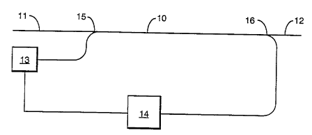
A suitable optical amplifier configuration is
illustrated, diagrammatically, in the ar , ying drawing.
The actual amplification is carried out in a fibre waveguide
30 10 which has a path region formed of a glass in accordance
with the invention. Thus the path region is a mixed halide
glass rnnt~;n;ng Pr3+ as the lasing dopant. The cladding of
the fibre is, conveniently, a compatible fluoride glass. At
its input end the fibre 10 is optically connected to an input
35 port 11 and at its other end to an output port 12. Both the
input port 11 and output port 12 are conveniently f ormed of
a silica fibre so~ that the amplifier is conveniently
.
342
Wo 95/26320 ~ o
- 19 -
rrnn~ct.~ into a t~l ,o, i cationg gystem wherein silica
fibre is, convPnt;~n~llyl used for tr~n~m;a~;r~n~ A pump 13
is connected to the fibre 10 via a wavelength multiplexer 15.
Pump 13 provides the power to d~ rlve the lasing of dopant
5 Pr3+. It is convenient to 'provide a splitter 12 which
removes a small proportion, e.g. 1-5~ of the amplified
signals for monitoring. The splitter 12 is connected to
control equipment 14 which monitors the strength of amplified
signal. Control equipment 14 is optically crnn~rt~rl to the
lû pump 13 80 as to increase or~ decrease the pump power in order
to keep the output of the amplif ier at a constant level . The
contr~l equipment 14 may also provide alarms when the output
of the amplifier falls below a threshold level.