Note: Descriptions are shown in the official language in which they were submitted.
2185~54
~d~nbf;cation and Control System for Prooessed and/or T~ansported Goods
The invention relates to a process for monitoring and/or controlling a predetermined series
of transport and/or processing operations by recognizing and registering the transported
andJor processed goods or the transport means (objects) at different stations.
Processing, distribution and storage facilities usually have many dif~erent processing stations
and transport paths. Depending on the tasks to be carried out and the final products, different
objects must pass through different stations and the transport paths between them. As this
happens, it is vital for the course of processing and transport steps to bç followed.
A typical example of an operation in which this problem is particularly important is a modern
slaughterhouse. There are many different processing stations, e.g., entry scales, flaying
stations, workplaces for removal of innards, washing and cleaning stations, meat inspection
stations, stations for cutting the animalc into large and fine cuts, etc. In large part, the
transport means on which the delivered slaughtered ~nirn~l~ pass through
, ., . ~ ~, . - - - .
Original Document
~8~354
these stations and ehe transport paths between them are meat hooks. In the cutting zones,
transport is frequently carried out on moving belts. It is necessa~y here to ensure not only
that the delivered slaughtered animal, e.g., an ox or a hog, undergoes all of the correct
processing steps, but also that the products obtained from a particular animal are
unambiguously matched to that animal at all times.
A typical example of a distribution plant where correct transport paths within the plant are
of crucial importance is a ~ook and periodical wholesaler. Each day, thousands of incoming
returned items must be sorled and delivered to the appropriate warehouses. Markings that
were originally found on the books or periodicals, such as bar codes and~ the like, have often
been removed in the meantime or are no longer legible because o~ damage to the article.
Tke automatic monitoring and control of such a series of processing and transport operations
is ~requently carried out by determining the respective locations within the plant of the
different transport means.
One way to monitor the transport means is to equip these means with transmitters. A
method of this type is described in the German Document Laid Open to Public Inspection
37 11237 A1. In this instance, each transport container is equipped with a transponder. The
transponder, which can be coded by a coding unit as often as desired, is electromagnetically
excited in the vicinity of a transmitting antenna controlled by an inquiry system and thus
emits a particular code, which in turn is received by the inquiry system.
Original Document
-, 2185~5g
Another common method is tO apply m~rkings or identific~tion means, e.g., bar codes, labels
~ith plain text symbols, etc., to the transport means or the transported or processed goods
th~rnselves. These markings or id~rltifiers are read by suitable reading devices at the different
stations.
~or exarnple, OS-l~E 32 05 189 A1 relates to a system for recognizing an orientation symbol,
which serves as an aid in automatic code reading during the sorting of packages.
In all of these methods, the transport means or the transported or processed goods themselves
must be specially equipped with identification means. When these ide~tification means are
active means, such as transrnitters or transponders, they are subject to wear and tear. In the
case of passive identification means, such as applied labels, the identification means frequently
become impossible to read clearly after a certain period of time, because of dirt or partial
damage; under some circumstances, they may even be read incorrectly.
The obje~ of the invention is to create a process for monitoring and/or controlling a
predetermined series of transport and/or processing operations of transported and/or processed
goods which does not require identification means or markings to be specially applied to the
transport means or the processed or transported goods and which operates reliably and safely
and can be easily installed.
This obiect is attained according to the invention in that at least a section of the object to be
identified is photographed by an electronic camera. The
Origin~l Document
~853'~
cha, a~ ;stic traits of the original surface and/or form of the o~ject are unambiguously derived
from the digitalized photograph by an image pr~cessing prograrn and then are summed up in
a characteristic code and stored and/or compared to previously stored characteristic codes for
the purpose of iclentifi~tion.
The subci~im~ that follow the first claim contain advantageous embodiments and further
developments of the invention.
The process on which the invention is based allows a wide variety of transported or processed
goo~ or transport means, e.g., transport hooks, crates that move on conveyor belts, bottles,
etc., to be identified.
Because the process accord;ng to the invention does not require markings of any sort to be
applied to the objects to be identified, it is especially advantageous when there is an open
circuit of objects, for example, when a plant uses no discrete tr~nsport means, such as crates,
hooks or the like, that could be assigned to particular goods, or when external transport means
enter the plant and subsequently leavç it again.
The characteristic codes of objects that enter the processing and transport sequence can be
determined anew and stored by the system in each case, and then deleted when these objects
leave the processing and transport sequence.
When changes occur in an object during processing, ~or example, when an object is divided
up into multiple pieces or multiple pieces are combined to form one new piece,
()riginal Document
- ~18~-~5l
these changes can be determined and stored in the same ~ay.
It is also possible to sort types of objects on the basis of their characteristic traits.
Advanta~eously, the picture taken by the electronic camera is first stored in an electronic
image memory of a computer in a pixel matrix.
All types of image processing routines and operations can be used on the picture stored in the
pixel matrix. For example, a Laplace operation results in harder edges and greater image
definition; mean value operations leads to smoothing at the expense of i~nage definition; and
medi~ operations lead to smoothing while edges are maintained. Zoom operations allow
particular details to be enlarged.
The pictllre of each object has characteristic traits that serve tO unarnbiguously identify the
object. These traits can be determined by an image processing program and summed up in a
characteristic code. Such traits include, for example, the shape and external dimensions of the
object, edges, depressions, elevations, holes, scratches, labels, etc. On the basis of these traits,
the unambiguous identification and recognition of objects, similar to the identification of
persons on the basis of fingerprints, is possible. The position and size of the traits relatiYe to
one another can be determined in the grid of the pixel matrix.
To allow different objects to be compared, the image processing program ad.~antageously
standardizes ~he position of each particular picture by resorting or readdressing the pixels in
the pixel
Original Doc~lment
~18~35~
matrix according to predeterm;ned criteria. It is also advantageous to select an area in the
position-standardized picture to be standardized by height and width, or to transform a section
of the picture that includes the object to be identified or ~ predetermined part thereof to a
predetermined size.
Preferably, a gray scale analysis is carried out with the standardized picture area. ~irst, the
gray scale values of the individual pixels are determined and stored in a gray scale value matrix.
In addition, a gray scale histogram (c~. Fig. ~) can be created.
The gray scale values of individual pixels can be standardized relative to a pre-established value.
In this way, different light conditions can be taken into account.
The characteristic code of each particular object consists of different trait sets. Which trait sets
are found and used for identification depends on the particular type of object, on the
particular task (sorting known types of objects, identifying objects changed in the course of
operations, etc.), on time-related information, e.g., identification speed, and on the degree of
difficulty of the objects.
~;or example, the positional coordinates and dimensions of the primary picture components,
i.e., object traits such as shape and size, edges, depressions, etc., can be included in a trait set
(A1, A2, ...). Furthermore, it is possible to determine gray scale value distribution parameters,
such as arithmetic mean v~lue, quadratic mean value, variance, half-value width, curtosis, etc.,
from the gray scaJe value histogram and to include these in another trait set (B1, B2, ... ).
Original Oocument
- ~8 j354
In addition, a Fourier analys;s can be carried OUt with the gray scale value distribution, and
the Fourier coefficients obtained from this can be included in another trait set ~C1, C2, ... ).
In a further advalltag~ous method, the picture is first transformed into a g~adient display, i
which each pixel is replaced by the gradient occurring at that point. In this display, the
characteristic traits of the pictured object with the strongest gradients are then determined, up
to a predetermined number of traits. After this, the gradient display is converted into a
display that discrimin~tes in reference tO a threshold value and stored The threshold value
lies below the lowest gradient value of the previously deterrnined traits The result is a "black-
white" image that constitutes the trait set in a matrix representation, wherein only the most
strongly characterizing traits are present In this way, the memory required for an image can
be reduced significantly. The image obtained contains only the important information, i.e,
the "fingerprint" of the object in question
So that it is possible for an object tO be recognized despite any slight changes that might have
occurred in its "fingerprint," it is advantageous to blur the black-white images that are to be
compared, i e, to make them less sharp This is ideally done by replacing, prior to producing
the gradient display, the gray scale value of each pixel by the median of the gray scale values
of the pixel itself and the pixels located in a given environment surrounding of the pixel.
Another option is to process the image, prior to producing the gradient display, with a
blurring filter that replaces the discrete gray scale values at the individual pixels by a Gaussian
distribution at a given width and
Original Document
~8~354 `
from this generates a new, less sharp gray scale value image. This process step can also be
carried out with the gradient display prior to discrimination relative to a threshold va~ue.
Another simple method-which, however, produces no defined blurring-is to merely set the
lens somewhat out o~ focus while the pictures are being taken by the camera.
Different minimum agreement conditions (WA, WB, WC, ...), which must be ~.ceede~l during
a comparison for the purpose of identification, can be established for different types of trait
sets.
Advantageously, prior to entering the processing or transport sequence, the objects are first
photographed by an electronic camera at an entry station; the data are stored in a central data
base. All other computers at the individual observation stations, as well as a central computer,
are networked with this central data base.
A processing or transport plan, which indicates what object is to pass through what station
at what time, can be stored in the central computer, for exarnple.
When types of obiects are to be sorted on the basis of their (known) characteristic traits, it
is also possible to place a library of object traits or even entire object pictures in the central
data base of the central computer.
If new objects are created during the course of processing, the characteristic codes of these
objects or the expected values ~or such characteristic codes can be s~ored in the central data
base or in
Original I~ocument
- 218~354
the cells of a neural networl~ simulated by the central computer. The expected values for the~e
new objects can include, for example, the external contours and the area encolllpassed therein
from various points of view. This takes into account the fact that objects pass by the control
station at di~l~ent orientations. Along ~ith data on the expected contours of a particular
ob~ect, expected values related to color composition or brightness variations on the surface can
also be provided.
It is also advantageous for the characteristic code of each object to include the time of
registration at the entry station. Based on the stored operational plan and the times at which
particular objects entered the processing or transport sequence, it is then 'possible, taking into
account the transport and processing times, to calculate in advance which objects can be
expected at a given control station and given time intervals with a particular probab;lity.
Then, in order to identify an obje~ at the gi~en control station, only the characteristic codes
of these particular groups of objects are used initially for agreement comparison. In this way,
recognition time can be significantly reduced.
The control stations signal to the central computer which of the objects has reached or passed
through a certain processing station or transport path. These data can be checked in the
central computer on the basis of the stored operational plan; in addition, the correct routes
c~n be set for conveying the object from this point to the next processing station or transport
path.
Onginal I~ocument
~1~5354
Prior to leaving the transport or processing area, tbe objects are advantageously photographed
again by an electronic camera at an exit station. The camera signals the exiting objects to the
central computer for control purposes. A job completion message can then be issued and the
characteristic code of the object removed from the central data base. If needed, a device that
provides each outgoing object with proof of identification and origin can be activated. For
example, this can ~e a label printer activated by the central computer that prints an
identification and origin label for each object destined for forwarding or delivery, which is
then stuck onto the object.
For optimal lltili7~tion of computer capacities, it is advantageous ~or object-sign~lling
in;tiators, such as light barriers or mech~nical or inductivç contact switches, to be arranged at
the individual stations. When an object is located in the precise image area of the camera in
question, these initiators send a release signal to the carnera, so that only in these instances are
digital pictures taken and stored. In th;s way, the unnecessary analysis of pictures that contain
no objects is avoided.
When a series of operations, for example, on an assembly line, must be controlled, complete
control areas can be formed by combining the directly adjacent or overlapping image areas of
different cameras. These areas can in turn be divided into directly adjacent or overlapping
control fields. If desired, one control field can correspond to the image area of one carnera;
however, this is not absolutely necessary. As a result, it is also possible to follow the objects
and their processing in a larger area.
Original Document
~18~35~
Of course, it is also possible, if desired, to divide an image area that can be seen by ~ single
camera into several control fields during analysis.
Original Doc-~m~nt
11
~185~-5g
The invention is described below in greater detail in reference to Figures 1 to 8 using the
example of use in a slaughterhouse. The drawings show:
Fig. 1 Schçm~tic overview of a slaughterhouse;
Fig. lA A control station with a meat hook, in side view, and a camera directed at this
with a light barrier as the release initiator for the camera;
Fig. 2 A rear view of a meat hook as seen from the camera;
Fig. 3 A pixel matrix with a sectional image of a meat hook; resolution into individual
pixels is not shown;
Fig. 4 A pixel matrix with a standardized image area of the mea~ hook;
Fig. 5 A gray value scale histogram of the standardized image area;
Fig. 6 A side view of a transport path, with a suspended slaughtered animal, and a
cutting belt with cameras arranged above it;
Fig. 7 A top view of the cutting belt with slaughtered anim~ls and animal parts
distributed thereon;
Fig. 8 A side view of the cutting belt with a camera arranged above it and the adjacent
cutti~g workplace.
Original Document
8~3~4
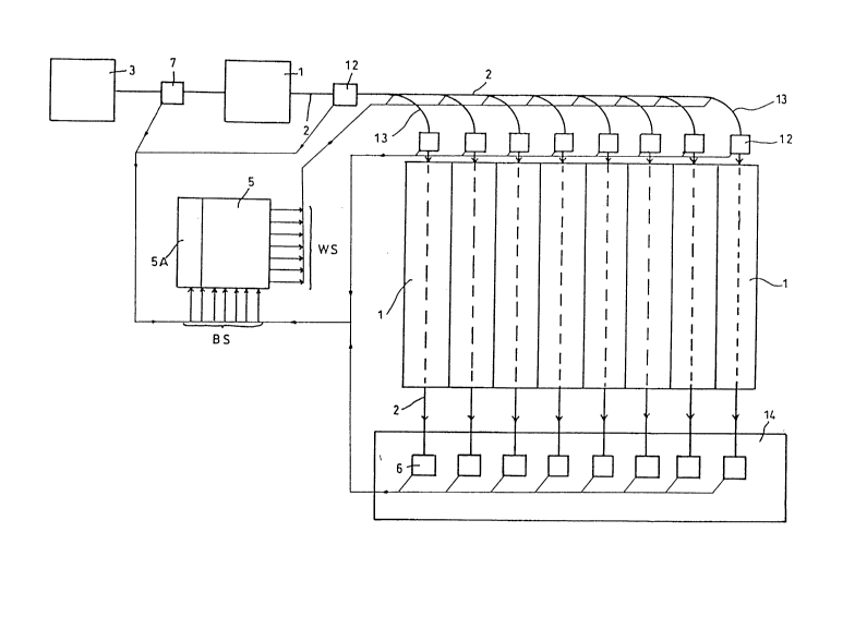
Figure 1 shows a schematic overview of a slaughterhouse. In the s3aughterhouse, there are a
large number of different processing stations (1) and transport paths (2). The anim~ls delivered
for slaughter are killed at a first station (3), suspended on a meat hook (4a) that serves as the
transport means, transported to an entry scale, and then transported further to the individual
processing stations (1), e.g., flaying stations, workplaces for removal of innards, washing and
cleaning stations, meat inspection points, large and fine cutting stations, etc.
Prior to entering the processing sequence, e.g., a~ter the killing station (3), each meat hook (4a)
with a slaughtered anim~l suspended on it is registered and assigned a job number or meat
hook number A processing plan stored in a central computer registers the correct entry time
and establishes which processing stations must be passed through by the meat hook with the
slaughtered ~nimal suspended thereon and through which exit station the meat hook is to
leave the slaughterhouse.
The following diagr~m shows an excerpt from such a processing plan:
Job No./ Entry Processing Stations Exit Stations
Meat Time
Hook No. V1 V2 V3 ... A1 A2 A3 ...
9:53 1 2 3 2 4 8
2 9:56 3 6 4 5 7 24
3 9:59 20 5 8 52 27 30
4 10:03 14 9 19 54 34 37
... ... ... ... ... ... ... ...
71 11:20 34 40 20 60 37 40
72 11:27 41 47 23 67 38 45
. . .
Replacement Page (Rule 26)
2~8~54
A meat hook (4a) that has entered the sl~ughterhouse is registered at an entry station (7). At
the entry station, a digital sectional picture (9~ is taken (cf. Figs. lA and 3) by a first electronic
camera (8) and stored in a pixel mat~ix (11) in an electronic image memory of a computer (10).
Figure 4 shows a pixel matrix (11) con~isting of 512 x 512 pixels.
However, the photographic matrix ~11) may also include more or fewer pixels, e.g., 256 x 256
or 1024 x 1024. The sectional picture (9) of each meat hook ~4a) has ~1n~nbiguous
characteristic traits identi~ying the meat hook (4a), which can be determined by means of an
image processing program and summed up in a characteristic code. The characteristic code of
each meat hook (4a) is stored in a central data base (5A). Characteristic traits in~lude, for
example, edges, depressions, elevations, scratches, holes and the like. An unambiguous
identification is possi~le on the ~asis of these characteristics.
In order to identify and recognize the particular meat hook (4a), its edges, depressions,
elevations and/or holes are found in the sectional picture (9), and their position and
dimensions in the grid of the pixel matrix (11) and relative to one another are determined by
means of an image processlng program.
.
Positional standardization of the particular sectional picture (9) is carried out by resorting or
readdressing the pixels in the grid of the pixel matrix (11) on t~le basis of predetermined
criteria using an image processing prograrn. A piclure area (~A) standardized by height and
width is then selected in the position-standardized sectional picture (9).
Original ~ocument
5 ~
Using the standardized pictllre area (9A), a gray scale value analysis is carried out. The gray
scale values of the individual pixels are found and stored in a gray scale value matrix.
An image of this type enconlpa~es 4096 bytes. 'rhe gray scale value of eæh pixel is then
replaced by the median of the gray scale values of the pixel and the pixels located in a
predetermined environment surrounding the pixel. After this, the picture is transformed into
a gradient image, i.e., the individual pixel value is replaced by a value corresponding to the
gradient at this location. In this gradient display, the traits most strongly characteristic of the
pictured object, i.e., the traits with the strongest gradients, are found, up to a predetermined
number of traits. A number of c. 800 traits has proved sufficient here. ~Next, the p;cture in
the gradient display is prc~essed with a (mathematic~l) blurring filter, blurring the contours
of the characteristic traits. Finally, the gradient display is converted into a display that
discrimin~tes in reference to a threshold value and then stored. The threshold value is lower
than the lowest gradient value of the previously determined traits.
The result is ~ black-white image in which only the characterizing traits appear. The picture
still has a memory requirement of 512 bytes. This "fingerprint" of the object is then stored
as the trait set.
Blurring contours by ~orming the median or applying the blurring filter is done so that even
if the "fingerprin~s" have changed slightly, the passing objects can still be classified.
Original l:)ocument
~85~5g
Irlstead of the rather complex mathematical contour blurring, the camera lens can be set
somewhat out of focus before the picture is taken. The process takes on some ~e~el of
uncertainty as a result, on the other hand, however, considerable time is gained. After this,
as described above in reference to the exarnple of meat hook recognition, a "black-white
fingerprint" of the picture is produced as the essential trait set of the object. This picture ;s
then compared bit-by-bit to stored pictures that are possible candidates for agreement, and the
picture with the greatest ~greement is sought. The time needed to identify a book by this
method can be less than 100 ms.
After the book has been identified, the computer issues appropriate ins~ructions, so that the
book makes it way to the desired warehouse area. At the same time, the pertinentinformation is passed along to the bookkeeping department of the warehouse, etc,
Before and/or after each of the processing stations (I) or transport paths (2), a digital sectional
picture (9) of a particular meat hook (4a) is taken by a further electronic camera (8) at the
control stations (12) and stored in a pi~zel matrix (11) in a digital image memory of a computer
(10). To recognize the particular meat hook (4a), the sectional picture (9) is analyzed by an
image processing program, as described above, and compared to the characteristic codes stored
in the central data base (SA).
Identification is carried out essentially by means of the bit-by-bit comparison of the "black-
~hite fingerprints" stored as the matrix-form trait sets. The
Orig~nal Document
16
- 21~5~
picture of the hook (4a) to be identified is compared to all other pictures of hooks ~4a) in
circulation that are possible candidates, and the hook (4a) with the greatest agreçment ~s
sought. A certain minimum agreement must be achieved, however. The minimurn agreement
threshold can be selected depending on the requirements of the particular plant. An
advantageous value is found at agreement of 60%.
Other trait sets ~e.g., time of previous or entry-side registration) are used for comparison, as
needed, in order to limit the number of "black-white images" to be compared. For example,
based on the processing plan and the entry times of the meat hooks (4a) into the prc~cessing
sequence, and taking into account the transport and processing times, it is possible to calculate
in advance which meat hooks (4a) will, with a particular probability, be at certain control or
exit stations (6, 12) at particular time intervals. In order to identify a meat hook (4a) at a
particular control or exit station (6, 12), only the characteristic code of this group of transport
means (4) is initially used for agreement compa~ison. In this way, recognition time is
significantly reduced.
After this, the centra~ computer (5) is signalled which of the meat hooks (4a) has reached or
passed through the particular processing station (1) or transport path (2). On the basis of the
processing pian stored in the central computer (5), a check is made to determine whether it
is correct for the identified meat hook (4a) to be at the control station in question. As needed,
a router (13) is set for conveying the meat hoo~ (4a) to the next processing station (1) or
transport path (2).
Original I)ocument
218~54
Exit stations (6) are located at the slaughterhouse delivery ramps (14), at each of which another
electronic camera (8) takes a digital sectional picture (9) of the respective meat hooks (4a). The
picture is stored in an electronic image memory of a computer (10). In order to recognize the
meat hook (4a), the sectional picture ~9) is analyzed by an image p,ocess;ng program and
compared to the characteristic codes stored in the central data base (SA). The central
computer (5) is signalled which of the meat hooks ~4a) has reached the exit station (6) in
question. A check is made, in reference to the proçessing plan, to determine whether it is
correct for the identified meat hook (4a) to be at the exit station (6) in question. As needed,
a job connpletion message or the like is issued and the characteristic code of this meat hook
(4a) is removed from the central data base (5A).
At the respective entry stations (7), control stations (12) and exit stations (6), there is an
initiator, preferably a light barrier (1~, 15'), which signalizes the meat hooks (4a) and emits a
release signal (AS) for the appropriate camera (8), so that a digital sectional picture (9) of the
sign~li7ed meat hook (4a) is taken by the camera (8) and stored. In addition, the time of
registration is signalled to the central computer (5) and can be included in the job protocol.
Instead of a light barrier (15, 15'), the initiator may also be a mechanical or inductive contact
switch.
In an alternative embodiment, pictures are taken by the particular camera (3) at periodic
sequential time intervals that are substantially shorter than the passage times of the meat hooks
(4a) through the
Ori~inal Document
-
control stations (12). In each case, a rough linear or columnar grid is established in order to
determine whether a meat hook (4a) is contained in the picture or not. If there is a meat
hook (4a) in the picture, the picture is stored for further analysis.
The central computer (~), the central data base (~A) and all of the other computers (10) are
networked ~vith one another.
The picture signals Q3S) ~rom the entry, control and exit stations are sent to the central
computer (5~. The routing instruction signals (WS) are established by the central computer
(5).
Until re~ching the cutting zone (16), the individual slaughtered anim~ls (4b) are transported
suspended on meat hooks (4a) and via transport rails (2). The process according to the
invention makes it possible to know which slaughtered ~nimal~ (4b) are suspended on which
meat hooks (4a).
When the cutting zone (16) is reached, the exit station (6) for meat-hook monitoring turns
over the appropriate identification start address to the analysis computer (5); advantageously,
the arrival or start time is stored at the same time.
The cutting zone (16) consists of a cutting belt (19) and multiple cutting workplaces (lB). The
slaughtered animals (4b) are moved from the transport path (2) onto the cutting belt (193. On
both sides of the belt (19), several people stand. These people cut up the animal (4a) into
partial pieces either directly on the cutting ~elt (19) or at adjacent cutting workplaces (18).
Original Document
19
21~3~4
Partial pieces (4c) that do not need to be cut up~ further are packed in crates at forwarding or
delivery stations (20) or attached to so called partial piece "pine trees."
In order to recognize and identify the slaughtered anim~ls (4b) and their partial pieces (4c),
there are multipIe electronic cameras (8) located above the cutting zone and directed at the
cutting belt (19), the cutting workplaces (18) and the forwarding or delivery stations (20).
Taken together, the cameras (8), with their adjustable picture areas, encompacs the entire
cutting zone. The cutt;ng ~one is divided into individual control fields directly adjacent to
or overlapping one another; a camera is assigned to each control feld of the picture area. All
cameras (8) are conn~ed to a central computer (5). At all of the forwarding or del;very
stations (20), there are label printers (17) controllable by the central computer (5), which print
an identification and origin label ~r each partial piece ~4c) destined for forwarding or delivery.
Preferably, these labels are collagen labels, which have no deleterious effect on the meat in the
area of adhesion.
On an ongoing basis, the cameras (8) above the cutting zone take digital pictures of the control
fields with the slaughtered ~nim~l.c (4b) and/or partial pieces (4c) located therein. These
pictures are stored in an electronic image memory of the central computer (5~ in pixel
matrices. Each slaughtered animal (4b) and each partial piece (4c) has traits that are
unambiguously characteristic for its identification, which can be determined using an image
processing program and are summed up in a characteristic code.
Original I)ocument
21~5354
A neural network is simulated in the analysis computer. In the cells of the neural ne~work,
expected values can be defined for each slaughtered animal (4b) and each partial piece created
in the cutting process. The traits of a partial piece (4c~ determined by the image processing
p~G~alll are then compared to the expected values for the purpose of identification. A
suitable identification address is then ~csi~necl to each partial piece (4c).
In the case of each successive partial piece (4c) created in the cutting process, several expected
values are defined for external contours and the are~ enclosed therein from different points
of view. In addition, expected values for the color composition of the partial piece surfaces
are provided. The cutting order is also taken into account in the expected values. To identify
and check a partial piece (4c~, a correlation is carried out between the traits determined using
the image processing prograrn from the pictures taken and the expected values of the neural
network.
The identification and control system according to the invention closes the gaps in the cutting
zone in the l'chain of proof" that reaches from the agricultural producer operation to the
supermarket. There is no interference with normal cutting operations.
In another example, the use of the process according to the invention is explained below in
reference to sorting returned items at a book wholesaler. This appl;cation is not shown in the
drawmgs.
Wholesalers often receive up to several thousand books per day that have been sent back by
book dealers because of erroneous orders or damages
Original Document
3~
or the like. Before being stored again, the books must first be sorted and brought to the
correct warehouse locations.
For this purpose, the books are first placed upon a moving belt. A camera is mounted above
the moving belt and takes a picture of each book. The picture is then ~ligit~ e(~ and
ànalyzed. To this end, the characteristic traits of all possible books are stored in a central data
base, as in a library.
In order to save time, the books in the present case are placed on the transport belt in a
certain position. However, this is by no means absolutely necessary, because reorientation is
also possible during analysis.
First, the height and width of the pictured book are determined on the basis of the picture
information. This makes it possible to considerably reduce the search steps needed in the
library to identify the book. Given a total of 6Q,000 possible books, for example, the number
of data sets to be searched per book can be reduced to below 2000.
The picture section that contains the book is then transformed to a predetermined size. The
image of the object is stored in a pixel matrix in the form of a gray scale value display.
Original ~ocl-m~ont