Note: Descriptions are shown in the official language in which they were submitted.
21 85360
wo 9!5127210 ' . . 5,1 .38
-- 1 --
.
AnalYsis method and analvsis a~oaratus
The invention relates to an analysis method, in
which several samples are passed in succession through
a reaction channel to a detector, and at least one
reagent is introduced into the reaction channel for
reaction with the samples. The invention relates
furthermore to an analysis apparatus having a sample
feed duct, at least one reagent feed duct, a pumping
device for sample and reagent, and a reaction channel
and a detector.
There is a constantly growing need for chemical
analysis in many areas. The area of environmental
protection can be quoted as an example. Here, for
example, when bodies of water are being monitored,
water samples have to be removed continuously from the
body of water and examined for contaminants. The
operation of sewage treatment plants, for example, the
injection of air, is effected in d~rF-n~ ce on specific
substances contained in the water to be purif ied.
Such analyses have to be performed at frequent
intervals, with the result that not only is the number
of analyses large, but these analyses also have to be
carried out as quickly as possible. The same applies
to the disciplines of medicine and environmental
analysis. In large laboratories, as a rule very many
samples have to be PYAmi nPd. This can no longer be
carried out using conventional manual methods, in which
the sample to be PYArn~nP~ is mixed with reagents, for
example, in a beaker, and a resulting reaction product
is recorded and evaluated f or type and quantity . An
additional complicating factor is that normally it is
not just a single reaction step that has to be carri~d
SU~3STITUTE SHEEr
21 853~0
WO 95/27210 . ~ a~ O
-- 2 --
out but a number of reaction steps. This not only
requires manpower, but also the provision of
cuLL~ n~ly large laboratory areas in which the
samples to which reagents have been added can be stored
in the interim until they have reacted and/or until tr-e~
reaction product has been evaluated. Il~euveL,
relatively large amounts of samples and reagents are
n~ct~Ccs~ry for the manual methods, which renders waste
r-n~j -r~ difficult.
For those reasons, a start was made some decades
ago on the development of continuous or semi-continuous
methods which could function with smaller sample sizes
and with fewer reagents. Because these methods have
been " -n1 ~ed" it is also possible to examine a
larger number o~ samples in the same time. The
methodology has been retained here, that is to say, the
sample is mixed with one or more reagents and the
resulting reaction product is detected using a
detector .
US 2 797 149 and US 2 879 141 describe a so-called
"Segmented Flow Analysis" (SFA), that is to say, an
analysis method in which successive sample segments are
separated by air bubbles in the sample duct. After
mixing each sample segment with one or more reagents,
the reaction product can be evaluated separately in
each segment. By choosing the length of the reaction
channel, the time available for the reaction can be
adjusted. The use of air bubbles in the reaction
channel to separate the individual samples produces a
compressible fluid column, however, so that the flow
speed, and thus the reaction time, cannot be accurately
monitored .
US 4 022 575 and DE 28 06 157 C2 disclose a more
recent method, which is known as "Flow Injection
Analysis" ~FIA). Here, the individual samples are
introduced at specific distances apart into a carrier
f luid so that successive samples are always separated
.
21 85360
wo s~r272l0 1
-- 3 --
by a segment of pure carrier f luid. This carrier
f luid partly charged with samples is then mixed with
the reagent or reagents. Evaluation of the reaction
product is effected in a similar manner by a detector,
which records the reaction produc;: according to type
and/or quantity. Because the samples are diluted by
the carrier f luid within a sample segment on the one
hand, and because of the transition between a segment
comprisiltg a sample-carrier fluid mixture and a segment
of pure carrier fluid on the other hand, which leads to
further distortion of the sample concentration at the
start and the end of each sample segment, in this
method there is only very limited scope for waiting
until a steady state obtains. The detector
accordingly no longer evaluates a signal at which a
constant reaction product signal is present, but a
transient signal, normally in the form of a peaked
signal pulse. The --_ --L~ of pure carrier fluid
between the individual s~ c of sample and carrier
fluid, referred to hereinafter as "sample ~ tc~ or
"sample blocks" for short, can be used to define a
starting point for each measurement. However, t~.te
dilution factor, also called the "dispersion
coef f icient" has to be determined in a separate test .
only from comparison of the dispersion coefficient with
the mea~uL~ L signal obtained is it possible to
determine the analysis result quantitatively.
Both known methods require only small volumes for
sample and reagents, compared with the conventional
manually performed analysis methods. Nevertheless, in
some cases considerable amounts of reagents are
required .
The invention is therefore based on the problem of
reducing the requirement for ~ hf-m;CAl c in such analysis
methods .
In an analysis method of the kind mentioned in the
il~LLodu~iLion~ this problem is solved in that s~tcc~cs;ve
.
21 85360
Wo 95/27210 r~ -
-- 4 --
samples are introduced adjoining one another into the
reaction channel.
Compared with the known methods, s~ c~scive
samples are therefore separated from one another
neither by ai r bubbles nor by segments of pure c2lrrier
fluid. The invention therefore departs from the
previously widely-held opinion according to which it
has always been regarded as necessary to wa6h out the
individual 6amples first before the next sample is
introduced. The invention i6 ba6ed on the realisation
that separation of the individual samples creates the
problem that the washing f luid or carrier f luid has
first to be wa6hed out with the next sample before a
mea,.~L~ L signal for this sample can be read out.
According to the invention, the preceding sample is
washed out with the next 6ample. The CCl~a~ _ ~ion of
time and f luid is drastically reduced by this 6tep,
becau6e the particular 6amples are not diluted by the
surrounding carrier fluid. In particular in
applications in which the E-~-c~Ccive samples are very
similar to one another, for example, in the repeated
removal of fluid6 from settling basins of sewage
purif ication plants, the measuring times and the
aon_ Lion of t-h~-rlic~l~ can be drastically reduced,
because the periods of time taken to achieve a stable
state in the following sample become substantially
shorter .
In a preferred i L, provision is made ~or
each sample, together with its associated reagent, to
form a block in the reaction channel, which block moves
with a laminar f low through the reaction channel, the
flow rate being selected in ~ _-.- e on the
dimensions of the analysis apparatus to be so low that
each block comprises a reaction 6egment which i6 ~ree
from 6ample and reagent of the preceding and subsequent
block. In thi6 reaction segment, the signal
determined in the detector is not disrupted by parts of
21 85360
~WO 95/27210 r~
-- 5 --
the samples of the adjacent samples. The distribution
of the reaction product in this reaction segment is
collse~uently substantially constant, so that the
detector output signal is likewise constant, that is,
has the shape of a plateau, which can be easily
evaluated .
It is also preferable for an integrating
mea:,uL~= t to be taken in the detector over a volume
which is smaller than the volume of the reaction
segment. This ~ on the one hand enables
local f luctuatiGns to be evened-out by integration, but
on the other hand, the integration volume is small
enough to ensure that errors as a result of inadYertent
incoLy.,L~tion of adjacent samples are not allowed to
occur .
Sample and reagent are preferably i.1~Loduced into
the reaction channel in a controlled manner so that
along the length of the block the local volume ratio
between sample an~ reagent, ~v~ clge:d over a segment of
predetermined length, is substantially constant, the
length of the segment being substantially shorter than
half the length of the block. The local mean volume
ratio is here a volume ratio which is present in a
hypothetical channel segment which symmetrically
2.ULLOUllds the site considered for the localisation.
This hypothetical channel segment therefore extends
from the considered site an equal distance in the flow
direction and against the f low direction. It has the
said predetermined length. When determining the
dimension of this length, it should be borne in mind
that it is small compared to the overall length of the
block. It is substantially smaller than half of that
length. The volume of the segment is therefore small
in relation to the overall volume of the reaction
channel and likewise small in relation to the volume of
the respective block. On the other hand, the length
of the segment should not be too short, since local
2~ ~5360
Wo 95/27210
-- 6 --
f luctuations in the volume ratio in the region of the
intake are expressly allowed. They are ~ ted
f or, however, in that int-n~ ; nA; by convection and by
diffusion of the participant fluids, that is, the
6ample and the reagent, takes place i.~ the reaction
channel, likewise locally. The length of the block
segment in question is therefore to be selected so that
averaging of the volume ratio over this segment
corresponds to levelling-out the fluctuation in the
volume ratio.
An i~LoAu~:~ion of sample and reagent which is
controlled in this manner ensures that in the
particular block being cc,.lv~yt:d to the detector there
is a substantially constant . A-At ratio between
sample and reagent. Accordingly, using the reaction
product it is actually possible to provide evidence of
the proportion of the substance to be detected in the
sample .
The local mean volume ratio between each
individual sample and its reagent is also preferably
substantially C~ L at any location of the reaction
channel at any time. The initial condition prevailing
only on il.LLoAu~;~ion is therefore maintained t~lIo~ uL
the reaction channel, f or example, by appropriate f low
control .
Preferably, volumes of sample and reagent, each
determined in advance, are fed with great accuracy into
the reaction channel. This great accuracy of the
infeed, that is, adherence to specific volumes and/or
flow rates, cannot normally be achieved with the
peristaltic pumps known from US 2 797 149 and DE 28 06
157 C2. These peristaltic pumps normally have at
least one resilient hose which is subjected to regular
deformation. It is virtually inevitable that this
deformation will lead in the long run to a change in
the delivery volumes. This change cannot be
predicted, however, so that even with an initially
21 85360
~Wo 95127210 p~,
-- 7 --
relatively accurate pumping, it is ; - i hle to ensure
that pumping of sample and reagent will be ef fecte~ in
the respective volumes detPrmined in advance. The
relatively accurate pumping, that is, matching of the
flow rates of sa~ple and reagent, therefore enables
exact predeterminable volume ratios of sample and
reagent to be set. The accurate infeed also enables
an i uv~:d consistency of the reaction ~loceduLas to
be achieved, so that the existing ~ni 70~1 method is
able to operate with virtually the same accuracy as the
conventional, manually performed methods.
In a preferred ~ LLUI Lion of the invention,
provision is made for sample and reagent to be
introduced in layers into the reaction channel. The
term "in layers" refers only to the instant of
introduction, however. As a laminar flow develops,
one can observe that a mutual dif fusion of sample and
reagent is effected at the interface or area of cQntact
between sample and reagent. The "layers" of sample
and reagent can theref ore no longer be exactly
separated a certain time after introduction.
Nevertheless, at least in theory it is possible to
imagine such a layering at the instant of introduction.
The two fluids of the sample and reagent are, as it
were, placed one against the another. This
arr~ L simplifies intPrmixinq of sample and
reagent in the region of laminar f low . The desired
reaction time can be achieved by a suitably 510w
advancement of sample and reagent through the reaction
channel. Mutual intermixing of sample and reagent can
here be attributed partly to diffusion. In a reaction
channel which changes direction, however, transversal
regions of flow also occur, which lead to in-L~ased
int~rmi7~in~ of the fluid by convection.
In an Psp~ri~l 1y preferred construction, provision
is made for more than two layers to be pL~.-lùced during
infeed, adjacent layers being formed by sample and
21 85360
Wo 95127210 . ~ 11L 13
-- 8 --
reagent respectively . The interf ace between sample
and reagent is thereby enlarged . If, f or example,
instead of two layers comprising sample and reagent,
three layers thereof are used, which f orm a sandwich-
like construction on the basis of the requirement that
ad~acent layers are formed by sample and reagent
respectively, the interface is doubled. The time
required for int~rmi~r;n~ decreases cuLL~,~v..dingly.
Sample and reagent are preferably fed into the
reaction channel parallel to one another in the f low
direction. In that c~se, there is a relatively large
interf ace which extends along the axis of the reaction
channel. There is therefore a sufficiently large
interface available for mutual diffusion of sample and
reagent. Exchange between sample and reagent is
maintained until the individual cu..u~ L~tions have
eq~ i z~. This exchange is not ~loron~nt on whether
the block formed by sample and reagent is moving
through the reaction channel or not.
It is here ~recii~lly preferred for the admission
of sample and reagent to be effected synchronously with
respect to one another. Such a ~y11~11Lu11uus admission
can be achieved, for example, by synchronously
controlled pumps, for example, by synchronously
operated piston pumps. In such a u u~ Lu~.~ion~ the
two f luids comprising sample and reagent are, as it
were, positioned side by side.
In an alternative construction, sample and reagent
can be fed alternately in succession and adjoining one
another into the reaction channel, the length of the
individual sample and reagent segments being
substantially shorter than the length of the block.
Although only the cross-sectional area of the reaction
channel is available as exchange area, that is, the
area which is also available for the flow through, the
individual ~P' tx of sample and reagent are here kept
relatively short, so that within a single sample-
21 ~5360
Iwo 95127210 1 -
_ g _
reagent block formed from a plurality of such e~ ' ca relatively large interface is accordingly produced.
Intc~rmiYing is then effected axially, that is to say,
in the f low direction .
Preferably, an overall volume of s~mple and
reagent COL ~ A; nq at least to three times the
volume of the reaction channel is fed into the reaction
channel. With such a large volume, one can ensure
that traces of previous blocks, that is, of previous
samples, have been removed completely from the reaction
channel. Despite the triple overall volume, the
c~n ~ion of chemicals remains relatively small owing
to the construction of the apparatus and its
miniaturization made possible by the method.
Advantageously, detection of the reaction product
is effected as the middle third of the overall volume
is flowing through. During that period, it is not
only possible to ensure with a relatively high degree
of probability that preceding samples no longer have
any inf luence on the reaction product of the sample
undergoing investigation at that moment, it is also
possible to avoid a subsequent sample having any ef~ect
on the reaction product.
The sample is pref erably f ormed by a f luid that
passes along one side of a membrane, the other side of
the membrane being exposed to a medium which contains
the constituent to be detected. In particular when
analyzing sewage, this eliminates r--h~nicAl removal of
the sewage f or the purpose of introducing it into the
reaction channel. On the contrary, the constituent to
be analyzed, that is, for example, a salt, phosphate,
nitrate or simil ~ substance, is transported through
the membrane in~ ~ he f luid . This ~L O~_edUL e is based
~S:sPntiAlly on d lysis. The method can therefore
t9 i epPnGP with additional mechanical working steps .
The flow rate is preferably selected so that with
a given cross-sectional area of the reaction channel, a
21 85360
Wo 9~/27210 r~
-- 10 --
Reynolds num~er ~or sample and reagent of 5 or less is
obtained . The f low rate is thus kept very low, which
has the advantage that the outward bulge developing at
the start of the block formed by the sample and reagent
and the uLLæ.yul~ding inward bulge at the end of the
block remain relatively 6mall. Accordingly, axial
intermixing ûf successive blocks is kept to a minimum,
so that relatively short blocks can be used without
fear that suc c~ ;ve 6amples will adversely affect each
other. The volume of the sample, and accordingly the
volumes of the reagents used, can thus be kept 6mall
whilst maintaining the quality of the mea:~ur c L.
The slow flow rate also enables the length of the
reaction channel to be kept corr~pponll; n~l y short
whilst maintaining the same reaction time, 60 that the
volume of the reaction channel overall can be kept
small .
It is also preferred Por the length of the
individual samples to be kept so small that the
analysis is effected continuously or semi-continuously.
In many cases, it is sensible not just to feed
individual samples in s~-c~ ion into the sample
channel, but to send a continuous sample f low through
the sample channel. It is here that the particular
advantage of the inventive method, which eliminates the
need to separate the individual 6ample6 from one
another, i6 d LLc.ted. By controlling the feed of
sample f luid and reagent f luid in such a manner that
the volume ratio is constant, even with continuous feed
the desired high accuracy is achieved.
With an analysis apparatus of the kind mentioned
in the il-L-o~ Lion, the problem is solved in that the
pumping device for each of sample and/or reagent has a
respective pump, the delivery amount of which is
controllable .
The choice of pump is of certain signif icance for
the present invention when one wishes to obtain
2 1 85360
W0 95127210 1 ~
accurate mea~uL. ~~L results with the method and the
apparatus. In that case, by suitable control of the
pumps, results that ~ ULL~ Vlld to those of conventional
- manual analysis methods can be obtained.
Using this ~ v..,~Lu~_Lion, the sample fluid and the
reagent f luid can be caused to enter the reaction
channel parallel to one another and at the same f low
rate. By this means, a layered ~LLu~;Lule transverse
to the longitudinal direction of the reaction channel
ls obtained. Mutual diffusion or intermixing of
sa~ple and reagent is not effected directly as the
sample feed duct meets the reagent feed duct, but
gradually somewhat later in the reaction channel, and
then pr~ ;nlntly by radial diffusion or mixing.
Axial mixing of successive blocks is avoided by this
measure .
The pump in this case is pre~erably in the form o~
a piston pump which is driven by a d. c . motor or
stepper motor. With a piston pump, the delivered
volume can be matched with great accuracy to a desired
requirement. Piston pumps can ~VV~::L also be
controlled synchronously with great accuracy, so that
pumping of sample and reagent can be coLL~,~vndingly
accurately and ~,y~ v--vusly controlled.
Advantageously, the sample feed duct and the
reagent feed duct are connected to two inputs of a feed
valve, which connects the two feed ducts alternately to
the reaction channel. In this ~ L, a layered
structure is produced in the reaction channel, with the
sample f luid and reagent f luid being arranged in layers
immediately adjoining one another. The adv~-- L of
a block f ormed in this manner From sample and reagent
is not n~ cF~rily effected continuously, but is
optionally in steps, because pumping cannot always be
guaranteed during the change-over operation of the f eed
valve. Nevertheless, even with this step-wise
.,
21 85360
WO ~5127210
-- 12 --
advancement of the block, satisfactory diffusion and
subsequent reaction of sample and reagent is achieved.
The f low cross-section of the reaction channel
preferably has a larger dimension in one direction than
in the direction at right angles to thib limension.
In particular when sample and reagent are fed in in
parallel, this allows a larger interface to be created,
which in turn promotes radial intDrm;srin~.
The flow cross-section is preferably substantially
rectangular. Infeed is then effected substantially
parallel to the longitudinal sides of the rectangle, so
that a ~JLL~ qly large interface is available for
hAnqe of sample and reagent.
The reaction channel preferably has a flow cross-
section of 0 . 5 mm2 or less and a lenqth of 250 mm or
less, and the pumping device generates a volume f low of
100 ,ul/min or less. The overall volume of the
reaction channel is COLL~ J~ rlillqly small. This also
means that only a very small amount of f luid is
required for the analysis . The very small volume f low
contributes further to keeping the consumption of
chemicals very small. Nevertheless, a construction of
the reaction channel of this kind enables excellent
results to be achieved.
It is also preferred for the detector to have a
detector volume which is smaller than the volume of the
reaction segment. The detector therefore integrates
only over a volume in which conditions are undisturbed,
that is, in which there is no influence from adjacent
samples .
The invention is described hereinafter with
reference to preferred ~ s, in conjunction with
the drawing, in which
Fig. l shows an analysis apparatus,
Fig . 2 shows a change-over valve in a f irst
position,
21 85360
~WO 95127210 P~ .
-- 13 --
Fig. 3 shows the chdllge u VeL valve in a second
position,
Fig. 4 shows a f irst construction of a mixing point,
Fig. 5 shows a second construction of a mixing
point,
Fig. 6 shows a third cu..:,LLu~Lion of a mixing point,
Fig. 7 shows a device for producing a sample f luid
and
Fig. 8 is a diagrammatic illustration of the mixing
and a signal plot.
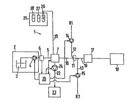
An analysis apparatus 1 comprises a carrier f luid
source 2, which in the ~ illustrated consists
of a reservoir 3 for carrier fluid and a pump 4. The
carrier f luid source 2 is joined by way of a carrier
fluid duct 5, in which a flowmeter 6 is optionally
arranged, to a cha~ OVeL valve 7, namely to its
carrier input 8 . The f lowmeter 6 is not absolutely
nPCGCC.Ary. If required, the amount of fluid delivered
can be determined from the delivery volume of the pump
4, for example, from its piston stroke. This can in
turn also be ascertained or controlled indirectly, for
example, by way of the driving power.
The chang~ Over valve 7 has a sample outlet 9
which is connected to a sample duct 10. The sample
duct 10 is connected in a manner known ~ se to one of
several mixing points 11, to which reagents R1, R2 are
f ed by way of respective f irst and second reagent ducts
12, 13 in each of which a respective pump 14, 15 is
arranged. A reaction channel 16, in which a detector
17 is arranged, adjoins the mixing points 11. The
output of the detector 17 is connected to a waste
collecting vessel 18.
The change-over valve 7 has a sample inlet 19
which is connected to a sample duct 20, which in turn
is c~nn~ctecl to a sample removal station, and a waste
outlet 21, which is connected to a waste duct 22.
2 1 85360
WO95/27110 .~I~r~
-- 14 --
Arranged in the waste duct 2 2 is a pump 2 4, the output
of which is c~nn~cted to a waste collecting vessel 23.
Different samples 26-28 are held in the sample removal
station ready to be sucked in succession into the
- ~hange-over valve.
In addition, a control device 29 is provided,
which is connected to the f lowmeter 6, if this is
present, and receives information from it. The
control device 29 controls the pump 4 for the carrier
fluid and the pump 24 in the waste duct 22. In
addition, the control device 29 controls the change-
over valve with the assistance of an operating device
30 in the form of a piston-cylinder arrangement. The
drive of each pump 4, 24 may, if desired, be coupled
back to the control device.
The change-over valve 7 comprises herein a
rotatable body 31 which is in the form of a stopper and
is arranged rotatably in a housing 32. The rotatable
body 31 has a first channel 33 and a second channel 34.
In the position illustrated in Fig. 2, the first
channel 33 connects the carrier inlet 8 to the sample
outlet 9, whilst the second channel 34 connects the
sample inlet 19 to the waste outlet 21. In the
position illustrated in Fig. 3, in which the rotatable
body 31 has been rotated through 9 0 with respect to
the position in Fig. 2, the first channel 33 connects
the sample inlet 19 to the waste outlet 21, whilst the
second channel 34 connects the carrier inlet 8 to the
sample outlet 9. The position of the rotatable body
31 can be reported to the control device 29 by way of
the line illustrated in Fig. 1 by the double-ended
arrow, between the change-over valve 7 and the control
device 29.
In the position illustrated in Fig. 2, the pump 24
sucks a sample 26 through the 6ample duct 20 into the
second channel 34, until this is completely full of the
second ~ample. Whether more sample is introduced than
2 1 85360
WO g5/272 10 1 ~ I ,~
-- 15 --
is needed to fill the channel completely is immaterial.
Complete filling of the second channel 34 with the
sample 26 ought to be ensured however. On rotation of
the rotatable body 31 through 90, the second channel
34 thus filled assumes a position illustI~.ed in Fig.
3. In this position, the second channel 34 connects
the carrier inlet 8 to the sample outlet 9. The
control device 29 now starts up the pump 4 for the
carrier f luid. The carrier f luid which is now being
transported enters the second channel 34 and thus
forces the sample located in the second channel 34
through the sample outlet-g into the sample duct 10.
The volume of the second channel 34 (and, of course,
also of the first channel 33) and the delivery volume
of the pump 4 are known. The control device 29 is
therefore able to stop the pump 4 for the carrier fluid
and to rotate the rotatable body 31 again through 90
into the position illustrated in Fig. 2 before the
carrier f luid is able to pass through the second
channel 34 into the sample outlet 9.
As long as the rotatable body 31 is located in the
position illustrated in Fig. 3, in which the second
channel 34 is emptied under the influence of the
carrier fluid into the sample outlet 9, the first
channel 33 can be filled with a su~sequent sample, for
example, the sample 27. As the pump 24 for the sample
has a larger output capacity than the pump 4 for the
carrier fluid, that is to say, has a larger output
capacity than the carrier f luid source 2, the channel
between the sample inlet 19 and the waste outlet 9 is
always completely filled before the carrier fluid
enters the sample outlet 9. In this manner, waiting
times are reduced. Control of the change-over valve 7
is conci~ rably simplified.
In the sample duct 10, a column of fluid is
therefore created in which one sample segment follows
immediately after the next without a gap. At the
21 85360
WO95/27210 PCTn~
-- 16 --
mixing point 11, the reagent R1 is added. At a
further mixing point, which i8 not separately shown,
the reagent R2 is added . Further mixing po ints f or
further reagents can, of course, also be present. The
reagents R1 and R2 ti/Qn react in the reaction channel
16 with the samples in the individual sample segments
and produce one or more reaction products which can be
detected by means of the detector 17. Once it has
s~rr-~csfully been evaluated by the detector 17, the
f luid in the reactLon channel 16 can be transported to
the waste collecting vessel 18.
Fig. 4 shows a first ~ ulll.LLu~:Lion of the mixing
point 11. The term "mixing point" has been chosen
here merely for reasons of simplicity. As apparent
from the following, the actual mixing does not take
place at this point. The sample duct lO and the
reagent duct 12 for the first reagent R1 meet at right
angles to one another here. Nevertheless, with
suitable f low control, the sample f luid and the reagent
fluid flow into the reaction channel 16 substantially
in parallel, provided that the f low rate is so low that
operation takes place in the laminar region. A broken
line 36, the s~ L:, of which become shorter and
shorter, indicates that the layering of sample f luid
and reagent fluid occurring directly at the confluence
slowly ~; e~rp--~rS . After a certain length, it is
; ~r~C~; hl ~ to detect a clear buu~ dL y between the
sample f luid and the reagent f luid in the reaction
channel 16. On the contrary, an increasingly
enlarging zone will form along the line 36, in which
sample f luid and reagent f luid mix with one another .
The mixing operation is effected here initially by
diffusion, that is to say, by an equalization of
dif f erenoes in concentration between the sample and the
reagent. Since this "~ i 7~tion is effected in both
directions, that is from the sample to the reagent and
from the reagent to the sample, this provides a very
21 85360
~W095127210 r~".
-- 17 --
good intermixing and after a certain time also a
complete intDrm; Y; n~ of sample and reagent. To reduce
the mixing and reaction time, it can also be sensible
to let the reaction channel change direction several
ti-~,es, for example, to CU~ LLUUL it in serpentine form.
Transversal f low portions then occur in each curve or
corner, leading to Inh~n~ ;nt/~rmiY;ng of sample and
reagent by convection.
The mixing point for the second reagent duct 13 is
of the same construction. As soon as sample and
reagent mix, that is, as soon as molecules from the
sample f luid have entered the reagent f luid and vice
versa, reactions can take place which ultimately lead
to the reaction product which is to be detected with
the detector 17.
Fig . 5 shows a modif ied ~ of a mixing
point 11', in which two reagent ducts 12 and 12' are
guided in such a manner that they emerge into the
reaction channel 16 on each side of the sample duct 10.
Both reagent ducts 12, 12' can be fed from the same
source or can even f orm two ends of a common f eed duct .
There are therefore two interfaces 36, 36'. It is
obvious that the UlJlJOL ~u--ity for sample and reagent to
intermix is ~I~c~ u~Sntly much improved. The time
taken to achieve a satisf actory intermixing is reduced .
Fig. 6 shows a third ~mho~l; L of a mixing point
11' ', in which sample and reagent are not introduced in
parallel into the reaction channel but in s~lrc~Ccil~n by
way of a change-over valve 37. As apparent from Fig.
6, very short segments of sample P and reagent R are
positioned one behind the other within a block, sample
P and reagent R following one another alternately.
This creates a plurality of interfaces 36' ' through
which the corresponding intermixing can be effected.
Fig. 7 shows a modif ied sample removing station
25'. One end of the sample duct 20 is immersed in a
reservoir 38 for a fluid, for example, distilled water.
21 85360
Wo ~/27210
-- 18 --
Usinq the pump 24, this distilled water is sucked out
of the reservoir 38. The sample duct 20 is connected
to a mixing channel 39 which is bounded on one side by
a membrane 40. On the other side of the membrane 40
there is a supply channel 41 which is in co~?~ection by
way of a supply duct 42 with a reservoir of the
substance or the f luid which is to be analyzed f or a
specif ic constituent. Pumping means, not illustrated,
convey the f luid to be analyzed through the supply
channel 41. As this is taking place, the constituent
to be analyzed, to which the membrane 40 is matched,
diffuses through the membrane 40 into the mixing
channel 39. It i6 taken up by the fluid flowing
through the mixing channel 39 . The f luid supplemented
with the constituent to be analyzed can then be fed by
way of the change-over valve 7 or even directly into
the sample line 10. In the latter case, analysis is
effected continuously. The length of the individual
samples can be regarded as infinitesimally small for
the yUL~J~.lSt:S of understanding operation. In that
case, the volume ratio between sample and reagent
f luids is kept constant not only over a block but over
several blocks or even permanently.
The control unit 29 controls not only pumps 4 and
24 for carrier fluid and sample, but also pumps 14 and
15 for the reagents. To ensure synchronous operation
of the pumps, all the pumps or their drives can be
coupled back to the control unit 29, so that the
control unit 29 is able to monitor the individual
delivery volumes. One should note at this point that
it is poæsible, of course, to use more than the two
reagent6 described. In some cases it will also be
sufficient to use just one reagent. The control
device 29 is able to control the respective pumps
syn~ ously with one another. The pumps are
preferably in the form of piston pumps, which are
driven either by a d . c . motor or by a stepper motor .
21 8536
095~2721û r~
-- 19 --
In this manner, it is possible to achieve an extremely
accurate setting of the delivery volumes of the
respective pumps. The control device 29 drives the
c~,L.esy~nding pumps 4, 25, 14, 15 in such a way that
very accurately control ~ ed f luid volumes enter the
reaction channel 16. This has the advantage inter
~lia that in fact a layering of sample and reagent can
be achieved in the rQaction channel 16 .
The control device 29 can stop the pumps 14, 15
and 24 from time to time, and indeed Por a relatively
long period of time, and operate just the pump 4, so
that the carrier f luid can be used to rinse out the
apparatus 1,
Fig. 8 shows diagrammatically a L~:pLcs_.-Lation of
the new analysis method. Adjacent sample segments Sc
are introduced together with their associated reagent
Ra into the channel in such a manner that the mean
local volume ratio between sample and reagent is
constant. Numbering of the sample and reagent
segments is not n~pcc~ry Der se, but makes
"accounting" and subsequent explanation easier. The
same reagent could, of course, be used for all samples.
Together with its reagent Ra~ each sample SD forms
a block B. At the instant at which it is introduced,
the leading and trailing interfaces of the blocks B are
aligned substantially evenly and orthogonally to the
direction of flow. The volume ratio of samples Sa and
reagents Ra are indicated beneath this initial
alignment. The lowest line shows the ratio of reagent
to total volume of sample and reagent.
At the end of the reaction channel 16, through
which blocks B flow wlth a laminar flow, two changes
have oc~;uLLc:d compared with the state on feeding in.
Firstly, the layers of sample and reagent can no longer
be distinguished from one another. on the contrary,
each sample has mixed with the reagent associated with
it. Secondly, an axial dispersion has taken place
~ ~ 21 85360
WO 95/27210
-- 20 --
between adjacent blocks, that is to say, the interfaces
between adjacent blocks are no longer even and
substantially orthogonal with respect to the direction
of flow. On the contrary, the blocks have "bulged
ou in the direction of flow at their leading end, as
is known from laminar flow profiles, and have "caved
in" in the direction of flow at their trailing end.
It is important here, however, that the flow rate, and
seu,uen~ly the extent of the CUL L . ~ 1 i n~
def ormation of the blocks, is selected to be so low
that in each block B there remains a segment ( "reaction
segment") b, which contains exclusively the respective
sample SD with its associated reagent R". Only the
reaction product that is of importance for the sample
5~ is theref ore present in this segment b .
The advantage of this arrangement is shown by the
plot of the signal at the output of the detector 17
which is illustrated at the right-hand upper side of
Fig. 8. The plot of this signal has separate plateaus
which are stable over a def inite period of time and are
joined to one another by individual transitions. The
plateaus can be evaluated with relatively little
effort .
The volume ratios of sample and reagent are
plotted beneath the "end portion" of the reaction
channel 16. ~ For the sake of simplicity, a linear
change of sample or reagent is assumed in the
transition regions between adjacent blocks. The
variations f rom the actual conditions occurring here
are negligible. Since the volume ratios of sample and
reagent also change synchronously and uniformly in the
transition seg~ent between two adjacent blocks, the
volume ratio between sample and its associated reagent
remains ~u1,:,Ld1-t also in these regions.
The detector, which always evaluates a certain
volume of fluid at a time, that is, has an integral
behaviour, will in this region detect both the reaction
2 l 85360
Wo95/27210
-- 21 --
products of a sample 5~ with its reagent R~ and the
reaction products of an adjacent block, that is, the
sample S~ + 1 with reagent R" + l. This creates t~se
transient transitions between individual plateaus.
But this has no influence on the fact that a1~er such a
transition a stable plateau is obtained again.
Because of the low axial dispersion, attributable to
the low flow rate, the individual blocks do not
intermix completely. But within a block there i a
very good intermixing, chiefly as a result of radial
dispersion. The detector has an integrat~-g effect,
that is to say, the measuring signal refle~ :s a kind of
mean value over a detector volume. This detector
volume is smaller than the volume of the reaction
segment. Although on the one hand this enables local
disturbances to be ~:v~Ded ~uL, on the other hand the
influence of adjacent samples on the mea:,UL~ L is
avoided .
The low f low rate has the advantage that the
reaction channel 16 can be made relatively short. The
n~ CcAry reaction time is nevertheless achieved with
the low f low rate .
By using blocks of sample and reagent that adjoin
on another, the preceding sample-reagent mixture is
washed out by the following one. This allows a
signif icantly faster sequence of mea~uL~ Ls of
individual samples because the dilution caused by the
known carrier fluid does not still have to be
eliminated f irst .
In a fir~t example, calcium is to be detected in
water. Here, a solution of 8-~ydLv~.yyuinoline is used
as the f irst reagent solution Rl . A solution of
ortho-cresolpthalein complexone is used as second
reagent. Table l shows some results obtained during
such an analysis of discrete calcium samples. The
frequency with which samples were taken was 30 per
hour. However, this frequency of analysis can, if
2l 8~360
Wo 95/27210 PCT/DK9S/00138
-- Z2 --
nr~r~ess;~ry, be increased without problems. The flow
rate waæ 90 ~l/min. The length of the reaction
channel 16 was 85 mm, and the cross-sectional area of
the reaction channel 16 was 0 . 2 mm2 .
Table 1
Time Calcium tppm Calcium (ppm
present) detected)
8 . 15 1 . 00 1 . 01
8 . 17 5 . 00 4 . 98
8.19 1.00 1.01
8.21 5.00 4.97
8.23 2.50 2.49
8 . 25 5 . 00 4 . 98
8.27 2.50 2.50
8.29 3.90 3.92
8.31 1.00 1.00
8.33 3.90 3.89
8.35 2.50 2.51
8.37 5.00 4.99
8.39 3.90 3.91
Before the measurement, it is useful to undertake
a calibration. For that purpose, analysis solutions
that have exactly known ~U~ LLatiOnS are used. The
treatment of the analysis solutions is effected exactly
as for the sample solutions. All parts of the
analysis system 1, including the carrier and reagent
solutions, should preferably be kept at a constant
predetermined t' ~ ULe:, in order to improve the
accuracy and precision.
A second example shows results for a continuous
analysis of nitrate in a sewage purification plant.
Here, a con:.~LuLion according to Fig. 7 is used, that
is to say, the take-up of nitrate into the sample
solution is effected by means of dialysis. One should
note that the construction according to Pig. 7 can be
used not only in place of the sample removal station
25, but also in place of the change-over valve 7. The
carrier fluid in this case flows past the membrane 40
21 85360
~h O 9S1272l0 ~ 8
-- 23 --
in order to take up the nitrate. By controlling the
pump 4 using the control unit 29, the .;~ ~ell time of
individual carrier fluid segments or blocks in front of
the membrane 40 can be adjusted. The outside of the
membI~ne can also be immersed directly in the sewage,
so that the supply channel 41 and the supply duct 42
can be omitted . The analysis can then be ef f ected
continuously, that is to say, the carrier fluid flows
past the membrane 40 continuously.
To analyze the nitrate, three reagent solutions
were required, namely, hydrazine, slllrhAn; lAmi~P and
N-~l-naphthyl)ethylene diamine. The pump 4 for the
carrier fluid and the three pumps for the three
reagents were operated continuously . The total f low
rate was 60 ~Ll/min. At specific intervals samples
were taken and analyzed using the method known from
DE 28 06 157 C2. In that method, however, cadmium was
used instead of hydrazine for the nitrate reduction.
Table 2
Time Nitrate (ppm) Nitrate (ppm
invention DE 2806157 C2
16.13 0.8 0.6
16.21 1.3 1.1
16.26 1.7 1.5
16.31 2.1 2.5
16.38 2.9 3.2
16.44 3.5 4.2
16.55 5.1 5.2
17.01 5.8 6.1
17.08 7.1 7.3
16.16 8.4 8.1
17.21 9.3 8.9
17 . 33 10 . 5 10 . 5
The average reaction time f or the sample and the
reagents is held constant in the system with a
continuous operation of the system, which means that
the rhc~mi~ I1 reaction is not necessarily fully
concluded when the reaction product passes though the
detector. In some applications it may, however, be an
21 85363
W0951~711~) r~"~.~. 138 0
-- 24 --
advantage to operate the system not continuously but
intermittently, so that a longer, but accurately
controlled time is available for the chemical reaction.
If, for example, the flow is interrupted when the
mixture of sample and reagent has reached the Qe':ector,
the chemical reaction can be monitored over a desired
time or until a desired level is reached. A second
reason for interrupting the continuous flow is that
with accurately controlled waiting times a larger
proportion of the constituent to be analyzed is able to
pass through the membrane 40, if such a membrane is
used .
Using the ~Lv~osed method, the individual sample
blocks are no longer separated by air bubbles or
segments of carrier fluid. On the contrary, they
adjoin each other without a gap. Sample and reagents
are f ed synchronously into a narrow reaction channel,
and relatively accurately controlled individual f low
rates are maintained. The shape and ~ inn!~ of the
reaction channel 16 are of some signif icance. Since
the cross-sectional area of the reaction channel 16 is
less than 0.5 mm2, and in particular less than 0.2 mm2,
and the length is less than 250 mm, and in particular
less than 200 mm, very few rh-,mic~ are rnn.
Furthermore, an elongate cross-sectional area is
preferred to a round or sguare ~:LVSS 3~_~ional area, so
that the interf ace between sample and reagent can be
made as large as possible, which improves mutual
int~rm;~in~ The overall flow rate can be kept below
lOO ~l/min, and in particular below SO ~l/min.
Altogether, a Reynolds number of 5 or less can be
achieved .
With the ~ LLu~_Lion illustrated in Fig. 6, very
accurate and predetermined volume percentages of sample
and reagents can likewise be introduced into the
reaction channel 16. In thiæ case it is assumed that
the addition of sample and reagent is effected
21 85360
Wo 9512721~
-- 25 --
periodically very accurately in order to keep the
volume ratio constant. Each addition is intended to
be very small in this case, so that the desired sample-
reagent ratio in the reaction channel 16 is achieved a
short distance after the mix:ng point 11''. The same
forms and dimensions of the reaction channel 16 as
those in the ~i ~ ';r ts illustrated in Figs 4 and 5
can be used here. In place of the change-over valve
37, the sample duct 10 and the reagent duct 12 can also
be led directly into the reaction channel 16 if the
pumps are operated alternately with the desired
accuracy. This can be achieved relatively easily in
particular if the pumps are driven by d . c . motors or
stepper motors. The pumps that are r~Cp~nci hlP ~or
pumping sample f luid and reagent f luid then alternately
receive a pulse 50 that they feed the desired small
amounts of sample f luid and reagent f luid
corr~cponrl i n~ y alternately into the reaction channel
16 .
When such an analysis apparatus is used for sewage
analysis in a purification plant, the amount of
chemicals required can be reduced to such an extent
that three litres per month is sufficient.