Note: Descriptions are shown in the official language in which they were submitted.
-
~ 85~6
RE 299~ PCT
A device for r~;lr~zl~7ins~ hin~lin,~ el~ -
5 The invention relates to a device which packages annular or
spiral binding combs for binding loose-leaf systems, in
particular annular calendars, notebooks, planners,
catalogues or advertising papers.
10 The said loose-leaf systems may for example be collated with
such binding combs, which may also be designated as binding
elements .
The binding combs are annularly or spirally shaped and are
15 normally produced from wire. The wire may be made from
plastics or also from a metallic material, which where
appropriate may be provided with a plastic coating.
Previously the prefabricated, i.e. the annular or oval
20 binding combs usually consisting of many loops and turns,
spirally shaped and still open in their longitudinal
direction were wound, transported and stored as endless
material on rolls. If necessary they were only then cut to
size corresponding to the format of the loose-leaf systems
25 to be bound.
In this case inter alia the relatively high weight of the
rolls to be transported is to be regarded as a disadvantage.
By virtue of the very high quantity of binding combs, the
30 described rolls are suitable only ~or large ~
however not for occasional use or for users who only require
small quantities of the described binding combs.
Since the loose-leaf systems have very different formats and
35 divisions and consequently different lengths o~ the binding
combs are required, the dimension to be cut has always to be
newly measured in each case.
21 8~42~
For this reason already cut-to-size 5maller quantities of
binding combs were already offered in so-called blister
packs .
However, by virtue of the blister made of a plastic, blister
packs do not take su~f icient consideration of modern
environmental awareness, and fur~h~ Le both manufacturing
and disposal costs for the blister are relatively high.
A device for presenting textiles such as transverse binders
is known from US-A-l 356 588.
In this case the device is designed in many parts and the
15 transverse binders are inserted into a depression in the
device, with four elastically deformable retaining strips
being biased and the retaining strips clamping each
transver6e binder at its outer sides so that the transverse
binder is retained in the device.
The object of the present invention is to create a device of
the type mentioned at the b~inn;n~, which is made from an
environmentally friendly material, can be produced without
great expenditure and which in a simple manner enables a
25 secure and easy packaging for already cut-to-size binding
combs .
This object is achieved in accordance with the invention by
a carrier plate which has several rows of elastically
30 bendable retaining strips, which :~ULL~UII'l the cut-to-size
binding combs partially in their base region.
As a result a simple and secure packaging and respectively
a stable base for the binding combs is created. The binding
35 combs which have already been cut to size and consequently
adapted to the formats of the loose-leaf systems can be
applied graded to the carrier plate.
~ . .
21 8~426
Since they are only partially ~ULl ~u~ded by the retaining
6trips, the binding combs can be removed easily and quickly
also by hand for binding the loose-leaf systems. The
5 carrier plates with the provided binding combs can
furthermore be easily stacked and can be stored and
transported in an ideal manner in matching containers.
If the containers are for example characterised with the
10 corresponding format details, fast access for the subsequent
binding operation is guaranteed.
By 6urrounding the binding combs in their base region is to
be understood that each retained turn or each retained loop
15 of the annularly or spirally shaped binding combs is
retained at the same region in the retaining strips. In the
case of a binding comb having an oval shape when seen in
cross section and for example still open at the top, the
base region is that broad side which lies opposite the open
20 part . In particular with this shape it is possible to f ix
the binding combs on the carrier plate so that warping,
twisting, changes in shape or a fast sliding out can be
avoided. Moreover the stacking of carrier plates provided
with binding combs on top of one another can take place very
25 uniformly and evenly.
A very advantageous development of the invention may lie in
that the elastically bendable retaining strips are
constructed in an H-shape.
The "H" shape has proved to be the most expedient during
experiments .
The stamping method is the most effectively applicable for
35 its manufacture.
21 85426
In this case the simplest procedure is if the retaining
strips are worked directly into the carrier plate. Above
and below the crossweb existing with this "~" shape
rectangular strips are produced, with which an elastic
5 behaviour can be most 6uitably produced. This behaviour is
necr~ ry for the bending of these strips for the purpose of
introducing the binding combs and their springing back after
provision for the purpose of retaining the binding combs.
lO The invention may furthermore be positively developed if the
spacings between the rows of retaining strips and also the
spacings and divisions between the individual retaining
strips within the rows can be varied in dependence on the
size and packing density of the binding combs.
Consequently it is possible to use carrier plates formatted
in the same size for varying sizes (diameters) of binding
combs .
20 Thereby both carrier plates having large binding combs and
also carrier plates having smaller sizes and therefore
greater packing density can be packed, stored and
transported in a single container.
25 It is also advantageous if the rows of retaining strips are
disposed parallel to one another.
Consequently the binding combs can not obstruct one another
during the provision. Moreover the available area of the
30 carrier plate can be utilized in the best possible manner
for provision with binding combs.
When providing with binding combs, which may take place both
with manually operated and also automatic machines,
35 indentation tools act from above on a row of retaining
strips and bend the strips downwards, as already mentioned,
so that the binding combs supplied from below in a retaining
~ ..
21 85426
device partially snap into the opening created in this
manner. By virtue of the already mentioned elasticity of
the retaining strips, the binding combs are adequately
retained and can be easily removed again for the binding of
5 the loose-leaf systems.
In the following operating cycles the same tools can
likewi6e act on the next rows of the retaining strips
advantageously disposed parallel. The supply of the carrier
10 plates may occur by varying means, e.g. via a belt conveyor
or by means of rolls or cylinders.
It is very expedient if for this purpose a transport edge is
provided on the carrier plate. The rows of retaining strips
15 should be disposed on the carrier plate in such a manner
that the transport edge remains at right angles to these
rows on either side.
It is also very expedient to provide the transport edge with
20 a rectangular recess in each case on its outer edges, so
that the transport means, such as rolls or cylinders, can
move the carrier plate without obstruction.
It is also very advantageous to provide positioning
25 openings, which are directly associated with the rows of the
retaining strips, extending in a line therewith, in at least
one of these transport edges.
The positioning openings can be shaped as desired. When the
3û carrier plate is positioned by means of a light barrier, a
square or rectangular shape of the positioning openings is
advantageous. If the carrier plate is to be positioned in
another manner, round holes or openings of other shapes can
be used.
These positioning openings form a so-called reference row,
by which the carrier plate experiences no undesired
_ _ _ _ , . . _ . _ _ . _ . .. . .. _ _ _ _ _ _
- 21 85426
deviation in position and thereby errors can be avoided
during the provision with binding combs.
For the illl~JLOV~ - lt in the rigidity and for an increase in
5 the moment of resistance of the carrier plate respectively,
it is very advantageous if the carrier plate has lateral
folding edges disposed parallel to the rows of retaining
strips .
10 The folding edges should be bent roughly at right angles
towards the component side. Thus it is possible to use very
thin material for the carrier plate, which is very
favourable for the weight, the stackability, the material
uul~u~ Lion and the ease of working such as e.g. that of the
15 cutting of retaining strips.
Of course the folding edge may also be provided on all four
sides of the carrier plate, so that the carrier plate has
the highest possible rigidity. In this case regard must of
20 course be paid to the fact that correspondingly suitable
devices are to be provided to transport the carrier plate.
The carrier plate may also be made from various materials
such as metal, plastics or cardboard (paper). For reasons
25 relating to the protection of the environment, cardboard
seems to be the most suitable as a good recyclable material.
The transport edge may advantageously run parallel to the
folding edges.
An exact positioning of the carrier plate f or covering with
the individual binding combs may also be guaranteed hereby.
In this case exact positioning can likewise be verified by
light barriers.
A very good stackability of the individual carrier plates
with the binding combs disposed thereon can be guaranteed in
~ ,.
~ 21 854~6
that the folding edges are at least approximately as high as
the height of the binding combs.
The individual carrier plates may consequently always be
5 placed with their underside on the upwardly bent folding
edges of the carrier plate lying llnr~rn~ath. Thereby a
carrier plate which is located right at the bottom in a pile
of carrier plates and respectively the binding combs
disposed on this carrier plate are prevented from suffering
10 damage by the fact that the mass of the carrier plates lying
on top thereof acts on the binding combs of the lowest
carrier plate.
An exemplified f~ho~ nt of the invention is described in
15 principle below by means of drawings.
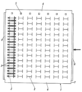
Figure 1 shows the plan view of a carrier plate for 7
binding combs with a represented binding comb;
Figure 2 shows the plan view of a carrier plate for 20
binding combs;
Figure 3 shows a binding comb retained on a carrier
plate in front view in a greatly enlarged
representation;
Figure 4 shows a binding comb retained on a carrier
plate in side view with the indentation tool
represented in a greatly enlarged
representation.
A carrier plate 1 is made from environmentally friendly
disposable cardboard, but may also be made from another
suitable material, such as e.g. plastics. The carrier plate
1 is approx. 333 mm wide and approx. 350 mm long. As
represented in Figure l, the carrier plate 1 has seven
vertical rows of retaining strips 2 f or seven binding combs
,.
21 ~5426
3 or binding elements respectively each with a diameter of
7/8" ( 22 . 23 mm) or 3/g" ( 19 . 05 mm), with one row in turn
consisting of twelve retaining strips 2. In total 84
retaining strips 2 are disposed evenly and parallel to one
5 another on the carrier plate 1.
The retaining strips 2 are cut in an H-shape into the
carrier plate 1, with the crossbar of the H-shaped retaining
strips 2 enclosing a so-called base region 4 (as can be seen
10 in Figure 3 ) of the binding comb 3 . The spacing or the
division for the retaining strips 2 inside a row is approx.
1" = 25 . 4 mm. The retaining strip 2 itself is approx. 22 mm
wide and 14 mm high. The upper retaining strips 2 shown in
Figure 1 are disposed with a spacing of approx . 40 ~m f rom
15 the upper edge. The horizontal spacing, i.e. the spacing
from one row shown vertically in Figure 1 to the next, is
approx . 4 3 mm .
At a distance of approx. 13 mm from the upper edge of the
20 carrier plate 1 positioning openings 5, also numbering
seven, are associated with the seven rows of retaining
strips 2. These positioning openings 5 run in the same
alignment as the rows of the retaining strips 2. They are
consequently parallel and provided precisely centrally over
25 each row at a distance of approx. 15 mm from the upper
retaining strips 2 and serve for the exact positioning and
prevention of deviations in the position of the carrier
plate 1, during its mechanical transport and provision with
the binding combs 3. The positioning openings 5 are here
30 shown in a square shape and have an edge length of approx.
6 mm. I~owever these could equally be designed round, for
example. It is possible to locate the positioning openings
5 e.g. via light barriers or other suitable measuring
devices .
So that the transport means, such as rolls or cylinders, can
operate without obstruction to convey the carrier plate 1,
21 8~42~
a sufficiently large transport edge 6 is provided above and
below the rows of the retaining strips 2 in each case. The
direction of transport of the carrier plate 1 is represented
by an arrow in Figure l.
However alternatively a tractor f eed of the carrier plate 1
would also be possible, as is known in conjunction with the
transport of paper in printers for data processing
equipment. For this purpose the carrier plate l would have
10 to be provided with a suitable perforation.
The outer edges of the transport edge 6 are in each case
provided with a rectangular recess 7 of approx. 8 mm wide
and approx. 15 mm long.
To bestow the carrier plate l with the required stability,
despite its material-saving low thickness, both outer sides
are provided with a folding edge 8 of approx. 5 mm wide.
The folding edge 8 extends parallel to the rows of retaining
20 strips 2 and is bent by approx. 90 to the component side.
In Figures l and 2 the folding edge 8 is shown not yet bent.
In Figure 1 it can also be clearly seen how the individual
turns of a binding comb 3 are constructed and how they
25 engage in the retaining strips. In this case the retaining
strips 2 do not enclose each base region 4, but only every
second or third, corresponding to the chosen division of the
retaining strips 2. A flat and secure retention and also
removal of the binding combs 3 is possible therewith.
In Figure 2 a carrier plate 1 of the same f ormat with
recesses 7, transport edges 6 and folding edges 8 of equal
size is represented.
35 Of course in this carrier plate l by virtue of the higher
specified packing density of the binding combs 3 (because
they have smaller diameters) 20 rows of retaining strips 2
_ _ _ _ _ ,
2 ~ ~5~26
are provided for 20 narrower binding combs having a diameter
of approx. 1/4" (6.35 mm) or also 3/16" (4.76 mm).
As in Figure 1, twelve retaining strips 2 disposed with a
5 division of 1" (25.4 mm) are likewise provided inside a row,
so that in Figure 2 a total of 240 retaining strips 2 are
evenly distributed.
The spacing from one positioning opening 5 and respectively
10 from one row of retaining strips 2 to the next is only
approx . 15 . 5 mm in this variant .
The 'lH~ r~cch~rl i.e. the width of the retaining strips 2,
in this case only measures approx. 7 mm, whilst the length
15 is approx. 10 mm.
Of course other spacings between the rows of retaining
strips may be chosen, according to the desired packing
density .
The side view of a greatly enlarged detail of a binding comb
3 retained on the carrier plate 1 can be seen in Figure 4.
Pneumatically, mechanically or hydraulically acting
25 indentation tools 9 from above effect the bending of the
retaining strips 2 downwards. As mentioned, the retaining
strips 2 are forced downwards, whereby the base region 4 of
the binding combs 3 ( as can be seen in Figure 3 ) engages
into the now opened crossbar of the H-shaped retaining strip
30 2 and by the elastic springing back of the retaining strips
2 retains the binding combs 3. The binding combs 3 retaine~
in this manner are conse~[uently precisely formatted and can
be easily manually or mechanically removed at any time.
35 In spiral and oval binding combs 3 such as those represented
in Figures 1, 3 and 4, which are open in the longitudinal
direction, the loose-leaf systems only need to be laid into
11 21 ~5426
the open loops of the binding combs 3 with the appropriate
number of corresponding openings. Then the binding combs 3
can be shaped to form a closed ring spiral.