Note: Descriptions are shown in the official language in which they were submitted.
2~1 85485
PROCESS FOR PRODUCING CHIP FOOD PRODUCT
AND SYSTEM THEREFOR
The present invention relates to a process for producing a food chip product
and a system therefor. An aspect of the present invention also relates to a frying
apparatus particularly suited for use in the present process and system.
Processes and systems for producing food chip products are known.
Generally, such known processes and systems fall into two categories.
The first category relates to a process and system for producing a food chip
product from a solid sliceable food. This would include the production of potatochips, sliced vegetable chips and the like. The second category relates to a process
and system for the production of a food chip product from a liquid composition.
Generally, this category relates to the production of corn chips and the like and
involves the use of a liquid composition cont~ining large particles of solid (e.g.
cornmeal) which is then dollc~ped in a frying medium to cook the composition thereby
rendering it solid.
To the applicant's knowledge, there does not exist a process and system for
producing a food chip product from a smooth batter composition which contains nodiscernable particles of food.
Another problem with prior art processes and systems relates to the known
fryers for use in producing food chip products. Specifically, to the applicant'sknowledge, conventional fryers comprise an integral tank for holding a frying medium
and heater for heating the frying medium. The design of this arrangement
necessitates the use of a high telllpel~lur~ heating element since, when the heating
element is disposed directly in the frying medium, for safety reasons, extreme care
must be exercised to avoid significant agitation of the frying medium (ordinarily, this
would assist in distributing the heat from the heating element throughout the frying
medium thereby lowering the required temperature of the heating element). Thus,
it is not unusual for a conventional fryer to have a heating element which is operated
at a temperature of approximately 1200~F. In contrast, the decomposition
temperature of most frying media (e.g. canola and other vegetable oils) is less than
500~F. Accordingly, significant and rapid breakdown of the frying medium is
21 85485
inevitable and, in the case of vegetable oils, this leads to the production of harmful
free fatty acids. For these reasons, the conventional fryer design of heating the frying
medium where it is cooking the food product is disadvantageous.
It would be desirable to have a process and system for producing a food chip
S product which could be utilized with a milled or refined batter composition free of
discernable particles of food. It would also be desirable to have an improved fryer
to cook a food product which obviates or mitig~tes the disadvantages of conventional
fryers discussed hereinabove.
It is an object of the present invention to provide a novel process for
10 producing a food chip product.
It is another objection of the present invention to provide a novel system for
producing a food chip product.
It is yet another object of the present invention to provide a novel fryer for
frying, inter alia, a food chip product.
Accordingly, in one of its aspects, the present invention provides a process forproducing a food chip product comprising the steps of
(i) extruding a liquid batter composition to form a sheet thereof;
(ii) conveying the sheet to a radiative heating station;
(iii) r~ ting the sheet to remove moisture from the liquid batter
20 composition to produce a non-liquid sheet;
(iv) conveying the non-liquid sheet to a cutting station;
(v) cutting the non-liquid sheet into a plurality of pieces;
(vi) conveying the plurality of pieces to a frying station filled with a frying
medium;
(vii) frying the plurality of pieces to effect cooking thereof to produce the
food chip product; and
(viii) removing the food chip product from the station.
In another of its aspects, the present invention provides a system for producinga food chip product, the system comprising:
an extruder having an orifice for discharging extrudate;
first conveyor means in communication with the orifice;
21 85485
heater means in communication with the first conveyor means and located
downstream from the extruder;
cutter means in communication with the first conveyor means and located
downstream from the heater means;
fryer means located downstream from the first conveyor means; and
second conveyor means in co~ ication with and downstream from the fryer
means.
In yet another of its aspects, the present invention provides a fryer comprisinga tank for receiving a frying medium in communication with a heat exchanger for
heating the frying medium.
Embodiments of the present invention will be described with reference to the
accompanying drawings, in which:
Figure 1 illustrates a perspective, schematic view of an embodiment of the
process and system for producing a food chip product;
Figure 2 illustrates a side elevation of a portion of the schematic illustrated in
Figure l;
Figure 3 illustrates an enlarged, side elevation of the U~ r~illl end of the
schematic illustrated in Figure l;
Figure 4 illustrates an enlarged, side elevation of a mid-stream portion of the
schematic illustrated in Figure l;
Figure 5 illustrates an enlarged top view of a mid-stream portion of the
schematic illustrates in Figure l;
Figure 6 illustrates an enlarged, side elevation of the downstream portion of
the schematic illustrated in Figure l;
Figure 7 illustrates a perspective view of an embodiment of the food chip
product prior to cooking thereof; and
Figure 8 illustrates a perspective, schematic of the present fi~er.
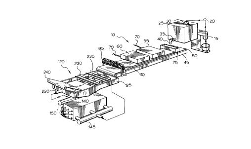
With reference to Figures 1 and 2, there is illustrated a system 10 for
producing a food chip product.
System 10 comprises a mixture lS which is connected to a holding tank 25 via
a line 20. Holding tank 25 comprises an inlet 30 and an outlet 40. Outlet 40
comprises a valve 35 which is operable to open or close outlet 40.
21 85485
Below holding tank 25 there is disposed a table 45. Table 45 comprises a
conveyor belt 50. Conveyor belt 50 is conventional in the food industry. Preferably,
conveyor belt 50 is constructed of a non-stick material (e.g. TeilonTM) and is capable
of withstanding temperatures of up to 500~F or even more. Conveyor belt 50 is
S driven by a suitable motor (not shown) of conventional design.
Disposed above conveyor belt 50 are a pair of heaters 55,60. Heaters 55,60
are preferably radiative heaters, more preferably infrared radiative heaters. These
heaters are conventional in the art and preferably comprise an array of radiation
emitting rods 65 which are able to emit infrared radiation, preferably having a wave
length of greater than about 750nm. Preferably, rods 65 are coated with gold. While
rods 65 are illustrated as being disposed longitu-lin~lly with respect to conveyor belt
50, it will be clear to those of skill in the art that rods 65 quickly displaced transverse
to conveyor belt 50. Heaters 55,60 are connected via a wiring harness 70 to a
suitable electrical supply (not shown). Upstream of heaters 55,60 is disposed to an
lS extruder 75. Extruder 75 comprises an open top 80 capable of receiving discharge
from outlet 40 of holding tank 45. Extruder 75 also has an orifice 85 which is
oriented for discharging extrudate directly onto conveyor belt 50. The height oforifice 85 will depend on the consistency of the batter composition (described
hereinbelow). Generally, it is pl~felled that the orifice have a height of less than
about 100 thousandths of an inch. More preferably, the orifice defines an opening
having a height in the range of from about 10 to about 60, most preferably from
about 10 to about 40, thousandths of an inch.
Located downstream of heaters 55,60 is a cutting station 95. Cutting station
95 comprises a feed roller 100 and a cutter roller 105. Feed roller 100 serves to lift
a dough sheet 110 off conveyor belt 50 and feeds dough sheet 110 to cutter roller
105. Cutter roller 105 in cooperation with feed roller 100 serves to cut dough sheet
110 into a number of pieces 115. Cutter roller 105 is rotated by a suitable motor (not
shown) in the direction of arrows 120.
Preferably, table 45 is equipped with a heater (not shown) which is capable
of heating conveyor belt 50 to facilitate heating of the batter composition. More
preferably, the heater is capable of heating conveyor belt 50 to a temperature in the
range of from about 80~ to 120~F.
2l8s485
Disposed downstream of table 45 is a fryer 120. Fryer 120 comprises a tank
125 for cont~ining a frying medium 130. Fryer 120 further comprises a heat
exchanger 135. Heat exchanger 135 comprises a container 140, an intake manifold
145 and an output manifold 150. Container 140 is sealed and comprises a plurality
of cylindrical tubes 155. Cylindrical tubes 155 pass through and are sealed withrespect to the interior of container 140. Disposed within each cylindrical tube 155
is a heater element (not shown).
_ach heater element (not shown) disposed in cylin-lri~l tubes 155 is connected
via wiring 160 to a power supply 165. Preferably, power supply 165 includes a
thermostatic control (not shown) for controlling the telllpeldlur~ of the heating
elements (not shown) disposed in cylindrical tubes 155.
Fm~n~ting from tank 125 is a pipe 170 which is connected to a pump 175.
Pump 175 is connected to a first filter 185 and a second filter 190 via a pipe 180.
First filter 185 and second filter 190 are connected to intake manifold 145 via a pipe
195. Pipe 180 is equipped with bypass valves 200 and 205, and pipe 195 is equipped
with bypass valves 210 and 215. Bypass valves 200,205,210,215 enables selective
bypass of first filter 185 and second filter 190 to permit cleaning thereof without the
need to cease operation of fryer 120. The operation of bypass valves
200,205,210,215 is within the purview of a person skilled in the art.
Output manifold is connected to tank 125 via a pipe 200. A pair of sensors
(not shown) are disposed in pipe 220 and container 140, respectively, and are
connected to power supply 165 via wiring 225. The purpose of this arrangement isto allow for thermostatic control of the operation of heat exchanger 135. Preferably,
this may be achieved using a solid relay control in power supply 165. The choiceand operation of such a control is within the purview of a person skilled in the art.
Fryer 120 further comprises a pair of paddle wheels 230,235 which are
disposed in tank 125 in a manner such that a portion of paddle wheels 230,235 isimmersed in frying medium 130. Paddle wheels 230,235 are rotated by any suitablemeans (not shown) and serve to convey pieces 115 through frying medium 130.
Partially immersed in frying medium 130 in tank 125 is a conveyor belt 240
comprising a conveyor belt 245. Preferably, conveyor belt 245 is constructed of a
suitable material which can with.~t~n-l immersion in hot frying medium 130. This can
21 85485
be achieved by the use of a food quality, metal mesh conveyor belt of conventional
design in the art. Conveyor 240 is operated such that conveyor belt 245 removes
cooked food chip product 250 from frying medium 130. As illustrated in Figure 6,conveyor 240 discharges cooked food chip product onto a supplementary conveyor
255. Supplementary conveyor 255 transports cooked food chip product 250 to a
p~ k:~ing station (not shown) or optionally, to a seasoning station (not shown) which
may include a vibratory seasoner for applying seasoning to cooked food chip product
25 prior to packaging thereof.
The operation of system 10 will now be described with reference to Figures
1-8.
Initially, a batter composition 12 is produced in mixer 15. The composition
of batter composition 12 is not particularly restricted. For example, batter
composition may contain 18 kilograms starch flour, 2 kilograms protein, 1 kilogram
fibre and sufficient water to achieve a viscous or syrupy consistency. The general
characteristic of batter composition 12 is that it is a milled composition which is
substantially free of discernable particulate material (compare with the conventional
composition used to produce corn chips which is a thick, abrasive, relatively unmilled
composition which cannot be extruded). Batter composition 12 is discharged from
mixer 15 into holding tank 25 via line 20 and inlet 30.
Preferably, batter composition 12 has a moisture content of at least about 30
percent by weight. More preferably, batter composition 12 has a moisture contentin the range of from about 30 to about 70, even more preferably from about 35 toabout 60, most preferably from about 40 to about 60, percent by weight.
When it is desired to operate system 10, conveyor belt 50 is turned on such
that it travels in the direction of arrow 260 (Figure 3 and 4). Valve 35 is opened to
allow batter composition 12 to enter open top 80 of extruder 75. The opening of
valve 35 is controlled to m~int~in extruder 75 substantially full of batter composition
12.
Batter composition 12 is discharged from extruder 75 as a sheet 265. At this
point, sheet 265 is still in substantially liquid form. Preferably, conveyor belt 50 is
heated to a temperature in the range of from about 80~ to about 120~F. Also
preferably, conveyor belt 50 is operated at a speed in the range of from about 2 to
21 85~85
about 10, more preferably 2 to about 8, most preferably from about 2 to about 6, feet
per minute. Of course, those of skill in the art will recognize that the speed at which
the conveyor belt 50 is operated depends on factors such at the temperature of the
downstream heaters, the number of heaters, the desired throughput of production and
5 the like. Accordingly, the speed of conveyor belt is not particularly restricted.
Sheet 265 is passed under heater 255 wherein it is subjected to sufficient heat
to remove moisture therefrom. As discussed above, this is preferably achieved using
an array of infrared emitting heaters. Preferably, the heaters emit a radiation having
a wavelength of at least about 750nm and result in heating the sheet to a temperature
of less than about 480~F, more preferably in the range of from about 350~ to about
450~. It is important, at this point, to avoid thorough cooking of sheet 265. Rather,
the intent is to apply sufficient heat to remove moisture from sheet 265 to transform
sheet 265 to a non-liquid sheet. The term "non-liquid sheet" is intended to mean a
sheet which will not flow and includes pliable, handleable sheets of dough. Ideally,
sufficient moisture is removed from sheet 265 such that the moisture content thereof
is reduced to less than abut 20 percent by weight. Preferably, after heating, sheet
265 has a moisture content in the range of from about 5 to about 20, more preferably
from about 5 to about 15, most preferably from about 10 to about 15 percent by
weight. At this point, sheet 265 is equivalent to dough sheet 110 referred to above
which is fed to fryer 120. Specifically, pieces 115 are discharged from conveyor belt
50 into fryer medium 130 in tank 125. Preferably, the frying medium is oil, morepreferably vegetable. Those of skill in the art will recognize that the frying medium
is generally liquid and that the nature thereof is not particularly restricted.
Preferably, fryer 120 is operated to ~A~ n frying medium 130 at a
temperature of less than about 450~F. More preferably the temperature of frying
medium is m~int~ined in the range of from about 350~ to about 450~F, even more
preferably in the range of from about 380~ to about 420~, most preferably in therange of from about 380~ to about 410~F. The key feature is that fryer 120 is of a
unique design which enables ~ i"~ ing the ~elllpel~lur~ of the frying medium below
the decomposition temperature thereof.
Paddle wheels 230,235 are operated to move pieces 115 through frying
medium 130 to conveyor 250. Conveyor 250 serves to remove cooked food chip
-7-
2 1 85~85
product from frying medium 130. Conveyor 250 discharges cooked food chip
product to supplementary conveyor 255 for further h~n(1ling as discussed hereinabove.
The operation of fryer 120 will now be discussed in more detail with reference
to Figure 8.
An ilnpo~ feature of fryer 120 is that, in normal operation, it continll~lly
circulates and heats frying medium 130. This is believed to be unique in that heating
of frying medium 130is conducted PxtPrn~lly to tank 125 where cooking takes places.
This design feature allows for more efflcient, low tempeMture heating of frying
medium 30 to avoid breakdown thereof. Thus, frying medium 130 is continuously
discharged from tank 125 by pump 175 via line 170. Frying medium 130 then passesthrough pipe 180 into one or both of first filter 185 and second filter 190. First filter
185 and second filter 190 are of conventional design and preferably comprise a
stainless steel or other filter which serves to remove particulates of greater than 40
microns from fryer medium 130. Filtered frying medium 130is then discharged fromfirst filter 185 and second filter 190 and fed to intake manifold 145 via pipe 195.
Frying medium 130 enters container 140 and passes, in a tortuous manner,
around cylindrical tubes 155 disposed within container 140. The number and size of
2 1 85485
Thus, the present process and system provide a means to produce a food chip
product from a finely milled relatively smooth batter composition. Generally, the
process involves removing moisture from the batter composition to render it into a
pliable, easily handled sheet of dough which may then be cut and fried. Thus, the
5 present process and system are readily adapted for use with any food sheet m~tçri~l.
Non-limiting examples of food products which may be produced in this manner
include nachos, tachos, pita, sheeted pasta, egg roll covers and the like. An
important advantage of the present process and system is that the equipment necessary
to produce the food chip product is relatively simple and large scale, commercial
10 operation may be effected at minim;ll capital expense.
While the invention has been described with reference to particular illustrated
embodiments, those of skill in the art will immediately recognize that various
modifications to the illustrated embodiments are possible without departing from the
scope and spirit of the present invention. It is of course the applicant's intent that
15 such modifications are included in the present application.