Note: Descriptions are shown in the official language in which they were submitted.
W095/25322 2 1 8 ~ ~ 2 ~ Pcr1c~95l00134
3~3 ~D SPOT D.3TECTO~ I
This invention relates to a blind spot detector ~or
use in moving vehicles, particularly, but not
exclu8ively! A71t~ R. It can also be applied to other
r7 ~rr~;rS7~irnF~ for example, detecting t~e presence of
children near a school bus
It has been a long rerorni 7ecl problem that the
driver of an automobile has a blind spot on either side
of the vehicle to the rear of the driverls prf:;t;nn in
which overtaking vehicles are not visible either in the
rear view mirror or the side mirrors. This can lead to
pot~nti;7lly ~7A~y~J P situations when the driver changes
lanes, part;r~1lArly in dense traffic. Quite often two
cars may proceed in pArAl~ with the trA;l;n~ car
~ ininrj i~ the blind spot of the leading car for some
crnFir7~ors7hle period of time. If the leading driver
changes lane~ without properly making a visual check of
his blind spots, a crlliP;on can result.
In the prior art, various A7 t~ ~3 have been made to
provide d~ot~rt;on devices for ~7~t~rt;n~ the rrl~C~onre of
objects in the blind spot. An example of one such device
is described in ~S Patent No. 5,122,796. This patent
~7.;ACI~7s~P a vehicle ~7~t~o~tr~r which employs an electro-
optical emitter for sending a light beam to a trr7;1;
vehicle and a receiver for picking up the light r~flect-~fl
from the vehicle. This device is typical of the prior art
in that it requires an active tr;~nF~i tti n,q element to
direct a light beam to the vehicle to be ~7~t~rt~1. US
Patent No. 4,260,980 discloses a similar alla-ly
employing 111trs~Frn;c waves. US Pate~t No. 3,697,985
discloses a system emp~oying Doppler radar systems.
The systems ~7~Prr;hl~fl in the above patent have in
common the fact that they are active systems; that is
they require the use of a trAnPn~i tt~r to send some sort
of signal which is r~fl~ct~fl off the tr~;ling vehicle and
ll
WO 95/~5~22 2 18 5 ~ 2 ~ PCT/CA95100~34
~ - 2 -
picked up by a detector on the leading vehicle Such
active devices are relatively expen6ive to make and are
very sen6itive to rnn~min~t;nn by dirt and the like
thrown up from the road Such active devices have a
5 significant power consumption and need to be hard wired
into the vehicle electrical system
IJS Patent No. 3,681,750 discloses a pasDive system
which relies on the detector picking up ultrasonic
~m;s~inn~ from the trailing vehicle. Such a device
10 reguires a frusto-conical horn to pick up the llltrnSnn;r
signals from the appropriate direction, but even with
such a horn the system has poor pn~;tinn;ll
disrr;m;n~tinn. ~Urth~ - e, the horn has a si~n;f;-Ant
size and thus impairs the aerodynamic and aesthetic
15 g,lA7; t~ of the vehicle .
US patent no. 5,249,128 A;~rlo~ the use of a
passive infrared A~ter~ tn~ for range sensing. ~here is no
teArh;n~ of blind spot A~t~ctinn or how to discriminate
vehicle signals from fal6e signalæ q~n~r~t~d, for
20 example, by the road surface.
An obj ect of the invention is to provide a small,
low cost blind 6pot detector that can }~e conveniently
to a vehicle without the need to hard wire it
into the vehicle ~- ~tr; CAl system
According to the pre6ent invention there is provided
a device for detecting the presence of an object in the
blind spot of a moving vehicle, ,- ~ ~;nq a pas6ive
infrared motion 6ensor ~hle on the vehicle so as to
have its field of view directed toward the blind spot,
said infrared sensor q~nor7t;nq a signal in LeD~ D~ to a
heat-emitting object moving about its field of view; a
hAnArA~s filter for passing signal6 having a rLe~ue~ey ';
within a pr~A~t~rm;noA band rh~r~ct~ tic of moving
vehicles; and an ;nA;rAtnr for ;n,l;c~r;nq the pre6ence of
wo gs/~ 2 1 8 ~ S 2 3 PCT~C~95~00134
-- 3 --
an object upon lPtect; nn of a signal in said
prP-lPtP~;nP~ band
The dPt~qctor ~rrnr~l;n~ to the invention is
- responfiive to the heat gPnPrAted by the engine of the
5 trailing vehicle. ~ simple low cost passive infrared
motion sensor, developed for the home security market, is
preferred. A suitable fiensor i5 dual element lithium
r~nt~lAte crystal with a low noise EET transistor mounted
on a ~ e and ~nrlnF~ in a metal housing with a
10 silicon window having part number ~iEIMANN I~I 958.
Such a sensor has a Fresnel lenfi with well defined
lobefi . The lithium tAntAl Ate crystals discharge when
infrared r~ t; nn falls on them. ~he~ an object moves
acrosfi the field of view of the ~lPtPCtn-, it moves across
15 the ~ oll~e lobea so as to ~pn~ tp an output signal. If
the two objects are stationary relative to each other, no
output signal is produced.
The vehicle carrying the sensor is of course moving
along the road. If the road surface were at a uniform
20 temperature, it would be produce no output signal. In
rr~ct; rP, due to differential heating the road surface
does produce an output signal at the d~t~ctnr that can be
as large as that caused by the trailing vehicle. It has
been found, however, that differential heating causes a
25 ~ict;nrtly aifferent signature from a moving vehicle
~:Pn~rAl 7y road signals r--;~---; ly lie in the fre~auency
range below 0 51Iz. These signals are mostly P~r~ Pd by
the b~n~lr~ filter.
When two vehicles are traveling in parallel along
30 the highway, the random motion of the trailing vehicle
across the field of view of the ~lPtPctor will result in
the ~lPt~rt; c n of the trailing vehicle even if the two
vehicles are moving along the road at the same speed
Such a ~7PtPctnr can be made at ~l ~y low cost
35 due in part to the fact that motion ~ensors are mabb
w095~s322 2~8~52~ PCJ/C~9SJ00134
_ 4 _ !
!
produced for the security market. The sensors are rugged
and consume low power since the control circuitry can be
made using CMOS devices. Using lithium batteries, the
battery life is P~ortP~a to exceed si~ months rnnt;mlcnls
5 use under average nr~r~tinr~ conditions. It is envisaged
that the device will be ;itt~rhoa, preferably adhesively,
to the side view mirrors of a vehicle and left
pP~-nPntly on. In the idle state, the current drair. will
be very small indeed
When a vehicle i8 detected, a light-emitting diode
will be ;11 n2ted, and this will be visible through the
side ~indow from the driver~s pof~;t;nn
Unlike most infrared sensing devices working in the
reguired t ~ tllre range, the inventive device does not
15 reguire a chopper, cryogenic cooling unit, or ~o~-~n;
lenses. Only a very si~ple s;~n~;n~ Cnna~it;nn;n~ circuit
is reguired.
The Fresnel lenses are preferably made of
polyethylene.
An important preferred aspect of the irvention is
the ability to adapt to rh~n~; n~ ~ t.Pnrnl r,~; r~l
cnnla;t;nn~. For example, in periods of heavy rain, car
si ~ eS are reduced due to the cooling effect of rain.
Fortunately, the road signature is also reduced due to
the fact that the thermal mass of the rain evens out the
t- L~ e v~r;Pt;nn~ in the road surface. In the
preferred ~ the invention exploits this effect
to adaptively adjust the threshold at which a vehicle is
considered present lalorona;n r on the nu~ber of noise
events ~lotectecl below the present threshold in a
pr~ torm;no~l period of time For examplê, if a large
number of noise events are flotectod, the threshold is
raised . If only a f ew are detected the threshold is
lowered This makes the flotertnr more sensitive, but only
w0 9~22 2 1 8 ~ ~ 2 3 PCT/C~95/00134
-- 5 --
when there is relatively little road noise, for e~ample
during periods of heavy rain.
The invention also provides a method of detecting
the presence of an object device for ClPtPf~;n~ the
presence of an object in the blind Epot of a moving
vehicle, characterized in that it co~,prises directing a
passive infrared sensor toward the blind spot, said
infrared sensor gPnPrZ~t;n~ a signal in response to a
heat-emitting object moving about its field of view;
passing signals through a ~ filter for having a
~rPq-lfnry within a prp~lptp~;np~ band rh~r~ftPr; ~tic of
moving vehicles; and ;n~ qting the presence of an object
upon ~lPtert;r-n of a signal in said rrPtlPtPrm;nP~ band.
The invention will now be ~lP~hPtl in n~ore detail,
by way of example only, with reference to the
-'3f- ~ ying drawings, in which~
Figure 1 is a plan view showing three vehicles
moving along adj acent lanes in a highway;
Figure 2 i8 a rear view of the vehicles shown in
2 0 Figure 1;
Figure 3 ifi a ~ ; c view showing the angular
~o--s~ of the infrared ~l~PtP~ tnr;
Figure 4a is a circuit diagram of the signal
conditioning circuit;
Figures 4b to 4f show the signal at various stages
in the signal cnn~l;t;on;n~ circuit; and
Figure S shows the voltage regulator for the
conditioning circuit;
Figure 6 shows the system field o~ view in the
direction of travel in more detail;
Figure 7 shows the ~ ;Pr frequency response of a
second . ';
i
WO 95/25322 2 18 ~ ~ 2 3 PC'r~CA9~/0013~
-6-
Figure 8 is a system block diagram of the second
' o~
Figure 9 is a top level flow chart describing the
op~rA~ t; nn of the second r--hotA~
Figure 10 is a noise ~ flow chart for the
second `~
Figure 11 is a flow chart showing the car detection
~rati nn of the second ~
Figure 12 is a flow chart tA~ rih;n~ the threshold
setting operation;
Figure 13 shows the lens cnnf;~lr~At;nn in
elevational view; and
Figure 14 shows the lens cnnf;~ Ati~n in plan view;
and
Figure 15 is a ~ t~ d circuit diagram of the
second: A ' ~ ~
Referring now to Figure 1, vehicles 7, 8 and 9 are
shown mo~ring along adjacent lanes of a highway, with
vehicles 8 and 9 in the blind spot on either side of
20 vehicle 7.
Vehicle 7 haæ side view mirrors 1, 2 with respective
passive infrared d~tectnr~ la, 2a mounted thereon. I~ach
infrared d~tect~r ha8 a hr'r;-'''ntAl field of view Q. The
field of view of n~otectnr la has respective outer and
25 inner edges 3, 4, whereas the detector 2a has a field of
view ~ with respect to inner and outer edges 5, 6. These
edge8 are chosen to outline the vehicle blind spot
Figure 2 shows the same layout from the rear, and
thus shows the field of view ~ of the detectors la, 2a in
30 the vertical plane. AS will be apparent from Figures 1
and 2, the ~ tPntnrs la, 2a have a generally ' ~d
directed conical field of view covering the vehicle blind
WO 95125322 2 1 8 ~ S 2 3 PCr/CA9510013~ ~
8pOt. Vehicles outside this conical field of view are not
normally detected.
The ~lPtertnrs la, 2a are normally mounted on the
side view mirrors with an adhesive. The detectors include
5 red light-~m;t~;n~ diodes that are visible from the
driver's position and that ;ll n~te when a moving heat-
emitting source is detected in the field of view ~, ~ of
the ~lPtectnrs la, 2a. This alerts the driver to the
presence of a vehicle in the blind spot, although before
10 switching lanes the driver should still make a guick
visual check by glancing over his shoulder
The passive infrared motion ~letect~rs employed in
the device have lenses that give an angular response as
shown in Figure 3, that is they have a series of radial
15 lobes 10 in the circumf erential direction . This means
that the detector has its greatest response along radii
a, c, with a minimum along radius b between the radii a
and c. The crystals are ~ P~7 80 that a st~t;nn;~ry
object pr~7llr~ a ~ero ~utput signal.
As an object moves across the field of view ~rom a
to c, the r~7;~inn received by the crystals within the
t~ctnr passes through a minimum at b maYimUm at c. mis
creates an output signal from the crystals, which in the
invention is used to detect the presence of an object.
me relative ~ of the obj ect and detector is
caused in part the random motion of the trailing vehicle
across the f ield of view of the detector.
This output signal is conditioned by the
Cnn~7;~;nn;n~ circuit 5hown in Figure 4a FPfPrrins now to
Figure 4, the signal conditioning circuit comprises a
clPte-rnr 20, a filter _7;f;Pr 30, an . lif;Gr 40, a
~ _ !nr 50 and a monostable circuit ~0. The cl~otPctor
;nnlll~7P,c: the passive infrared sen50r 21 which is 8llrr~;
with steady voltage V2 provided by the voltage re~ nr
shown in Figure 5 . The voltage V2 is s~lppl; P~ through
WO 95f25322 2 1 ~ 5 S 2 3 pCTlC~.9510013J, I
series resistors Rl, R2. These resistors in conjunction
with the capacitor C, provide a ripple-_ree voltage supply
to the sensor 21
The output voltage of the detector 20, which is in
5 the microvolt range, i8 shown in Figure 4a When a target
is ~l~t~ct~l, the spike 22 occurs.
The filter/ _l;f;Pr 30 ~r;~ two np~r~t;o
~mrl;f;~rF: 31, 32, which form a band pass filter that
matches the output L- e.~ y response of the infrared
10 sensor and rl;~rr;m;n~tes vehicle response from road
noise. The circuit also provides a s;rJn;fir~nt amount of
gain, providing an output signal in the millivolt range
as shown in Figure 4b
The output of circuit 30 is applied to ~ r
15 circuit 40, which comprises opPri~t;nn~l l;fi"r 41
This provides further l;f;r~t;rn and also DC filtering
through ~r~r; tnr C8 . The output voltage is offset with a
voltage provided by resistor network Rll and R12 The
output of _ l; f; ~r circuit 40, which is shown in Figure
20 4c, is a circuit in the millivolt range.
The output _l;f;or 40 is applied to co~parator 50,
~- ~;n~ r~rat;onzll, _l;f;-~r~ 51, 52. ~'~ _ r,r 50
is a ~q~r;~ n-making circuit that defines upper and lower
bounds of thè input signa~ (Figure 4d). These are set
25 with variable resistor R15, which therefore sets the
sensitivity of the circuit. When the - - ~nr 50
registers the target, due to the signal falling outside
the upper and lower bounds, as shown in Figure 4d, the
r produces a _alling edge voltage signal of
30 small ~ r~tirn at its output. This filter signal is in
the volt range and is applied to _ ~hle m~ultivibrator
60, which is a falling edge triggered circuit used to ~ -
prolong the duration of the output signal of the
c _ rr me output signal, shown in figure 4e, is an
35 output pulse whose ~lllr~tirn is set by resistor R20 and
WO 95/2S322 pCTlC~9~/0013~1
~ ` 2185S23
9.
capacitor Cll The ontput o~ monostable 60 is a voltage
Gignal in the volt range, which is used to drive LED 62
that acts as a visual ;nA;c~trr to the driver of the
presence of a target.
The conditioning circuit shown in Figure 4 is
implemented in CMOS and therefore has very low power
cv~u,~ion. This i8 also helped by the fact that it i8
purely a passive, non-r~A;~tin~ device
The detector normally operates in the 6 to 14 micron
10 long wave infrared ~ t;nn and is ~Pn~r~l ly responsive
to the heat emitted by the engines of moving vehicles. It
has bee~ found that the device responds well to vehicle
engines with minimal false ;nA;r~;r,nc
While the device has been desig~ed particularly with
15 ~ ' 1P~ in mind, it can be applied to other
applications, for example aircraft ~l;n~t;oncl where
there is a need to detect the yL~5~:uc~ of heat-P"~;tt;
targets
The d~tertnrs are ~tt~rh~d to the side mirrors by a
20 durable automotive adhesive. Since they are self-
rnn~;n~l and battery QpGr~tPd, no wiring or electrical
rnnnPct;rn to the vehicle PlPr~ric~l system is required.
This means they can be distrih~ltPd as low-cost
accessories for easy non-invasive ~ ;r~t;nn by the
25 vehicle owner. ~11 he has to do is stick the device in
the appropriate poc;~;nn where it is visible from the
driver~s pos;r;on through the vehicle window
By using a lithium battery, rr,nt;mlnllc opPr~t;~r,n in
excess of six months can be achieved. The device is not
30 designed to be switched off. When no target is detected,
the current con~, , ; r,n is nominal .
If desired, an ~AA;t;nn~l LED having a different
color, such as a amber LED, can be provided to give early
warning of a low battery condition.
WO 95/25322 2 1 8 ;~ PCT/CA9~10013.
- 10 -
The optics of the passive ;nfr~rPcl detector will now
be discussed in more detail with reference to Figures 6,
13 and 14 This infrared detector could be used in either
the first: -' discussed above or in the second
5 ~mhoA1 - to be described below
me infrared A~t~rtor only responds to changes in
observed t~ _ t e across its field of view. Thus, it
is only pOSS;hl.Q for the system to detect objects which
cross the field of view. Objects colaing straight towards
10 the 6ensor produce little or now response. For this
reason the FoV is angled out from the vehicle direction
by about 20 +5~ so that vehicles entering the blind spot
actual are f orced to cross the FoV.
Secondly the optimum focal length has been found to
15 be about 25 mm. Shorter focal lengths give a larger FoV
~field of view), but produce a lower effective car
frequency ~ign~tl~re. miS makes ~r~r~t;nn of car and
road ~ S A;~'f;rl~1t or ~ -_ hl-o, Longer focal
lengths have several disadvantages:
a) me llaL~ L spot beam requires better
alignment .
b) The beam may not cover the hot spot on the car.
c) More lens ~ are required to give the
reguired hnr~7rmt~7 coverage.
d~ A larger physical size of the unit is required
to house the larger optics.
The optics is ;3r~ to give the FoV shown in
Pigure 6. The ~1;5 must be fairly precise to get
this FoV Three angles are involved which can be termed
30 yaw, pitch, and roll. Yaw A~t~rm;nF~ the Tlnr;7-~nt~1 FoV
and is least critical of the three It is est~hl i ch~A by
the user simply by aligning a reference line towards the
rear of the car. Tnl ~r~nce is + 5 . The roll angle
Al~t~rmin-~: the extent to which the FoV extends to the
,
w09s~22 2 1 8 ~ ~2 3 PCI/C~ 95/01)13~ i
~' - 11 -
side of the car. Ideally the FoV of view would be limited
to the adjacent lane (3.5 m) In fact, it is chosen to
extend slightly beyond this so that sufficient signature
is picked up f rom cars in the blind spot . me result is
5 that ocr~qinn~lly there will be triggering from cars one
lane over Roll angle should be 15 ~ 2. Pitch i8 the
most r~r;t;C~l angle and ~7PtPrm;nPq h~q1c~11y how far the
FoV extends behind the car . If it is too high ob~ ects
very far away (b7~ 7;n~q, setting sun etc.) will give
10 false triggers. If it is too low the vehicle will not be
~7PtectPfl until it is well into the blind spot. Pitch
angle is set to 1.5 i 1.
Pitch and roll angles are set by the user placing a
circular level on a surface of the device which when
15 level is set to give the correct roll and pitch angles.
me device la, 2a uses eight lens elementa
(i. . .viii) to give h~r; ~nt~l coverage o~ about 60, as
shown in Figure 13
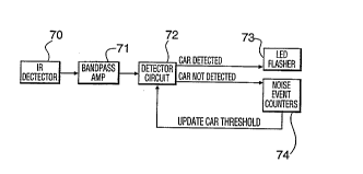
The second: ' ' , as shown i~ Figure 8, has a
20 passive infrared detector 70, a hanflr~qq ,l;f;Pr ?1, a
detector circuit 72, an LED flasher 73, and a noise event
counter 74.
The: l;f;Pr 71 has a specific b~nflr;-qq
l~h~rPrtPr;qtic to provide near optim 1 dis~r;m;n~t;on
25 between vehicle and road ~ackground signatures. It has
been detern7ined P~pPr; lly that with proper optical
alignment, the electronic siy~Lu eb of vehicles lie
rr;r-r;7y in the region above 0.5 Erz~ while the
electronic s;~n~t~res of the road background lie
30 primarily below O.s ~z
In bright sunshine because of differential heating
o~ the road surface, the ba~ylvu~d signature can easily
be as large as that of a vehicle so that it is vital that
these siy~ Lu~ es be filtered out. The device has in fact
35 three filters with high pass cut offs at 0 08, 0 7 and
-
wog~322 2 1 8 5 ~ 2 3 pCI~/CA95J00i3~ `
-- 1 2 --
O . 7 ~Iz, respectively. As well a second order low pass
filter cut off at 4.2 ~z is used to limit high fre~auency
noise. The filter response is shown in Fiy-ure 7.
The ~; ~n~tllre received from cars i8 strongly
5 r1~r~n~lPnt on weather cnn~;tinn~. Particularly in medium
to heavy rain, the &ignature from vehicles can be
.' ;r~qlly reduced. Fortunately, it is possihle for the
device to ~ t~rm;n~ when this ~nni;t;~n eYists by
nitoring h~ J, ,u i noise as the h~rk~rolln~l sig~ature
~0 is reduced as well during rain - i . e . the road tends to
be of re uni~orm t ~ I._LaLUL~:: due to the high thermal
- mass of the rain water.
The blind spot elPte~ctnr takes advanLcly~= of this
e__ect by collnt;n~ noise values over a given threshold in
15 the noise event counter 74. ~fter a l~L~ ;n~ period,
a threshold is chosen that depends on the number of noise
counts over the roise threshold. Eligher counts give
higher thresholds The period is ~t~n;nP~l by rmlnt;ng
the numher of samples below the lowest possible car
20 cl~tP~-t;~n threshold. Thus, the St~t;~t;r~ are not upset
by the presence or absence of vehicles in the blind spot.
Sper;f;r~lly, with the ,,l;f;~r gain set to 66 dB
the noise threshold used is 30 mv. The po~3;hl~ cæ
detection thresholds are 50 mv, 100 mv, 150 mv and 200
25 mv me count is done to a m~ximum of 32 events below 50
mv Each event is sampled for about 800 msec so that a
new threshold is chosen about every 25 sec if no events
over 50 mv occur. The threshold for the next 25 sec
interval is set based on the numher of events between 30
30 and 50 mv as follows:
less than 3 events m = 50 mv
between 3 and 7 events m = loo mv
between ~ and 20 events m = 150 mv
more than 20 events Th = 200 mv
WO 95125322 2 1 8 5 S 2 3 PCT~CA95/00134
- 13 -
A time out check is alGO ;~r7 ~-1 to prevent the
system locking up due to constant noise or car signatures
over 50 mv. After one minute of this condition, the
threshold is set to 200 mv.
The detailed ortPr~t;nn of the second ~ - ,
which is mieLu~LuCeSSOr based, is illustrated in Figures
9 to 12.
The detailed circuitry for the second: ' ' is
shown in Figure 15 The circuit is controlled by
microprocessor 100, which is a Motorola 6805 A signal
from passive infrared ~9Ftecto~ 101 is fed through
operational ~ ~ 1 i f i ~~~ 102, 103, which also act as
b~n-lr~s filters. The output of; _l;fi~r 103 is fed to
op~rFIt;nn~l: 1ifi-~rS 104, 105, which acts as
~ , ~ o~. Switches 106 provide the threshold
adj__ circuitry.
The invention also has other ~rrlir~ti,~nc, such as
school bus child detectors. An inte~r~t~d Multiple unit
could cover a long vehicle, such as tractor trailers.
With the current invention, pickup of shadows from
overpasses call occur, in particular on sunny days. This
is because of the cooler road t ~ ~ under the
underpass. It is possible to -~ e for this hy
having two d~tPctnrs with one pointing straight down at
the road to establish the ~le~ell~e of a shadow. This
information can then be, n~ with the data from the
car detection sensor to reduce the ~tert; nn of shadows .
The current iIlvention takes advantage of the
relative motion of the two vehicles to produce the
~l~tertion signal Normally in most driving s;tll~t;nn~:
this is s~lf~in;~nt to give a very high prnh~hil;ty of
detection. }Iowever it is conceivable, ~pe~;A~ly under
heavy rain when car s; ~n~tllres are reduced, that relative
motion may not be enough to trigger the device This
35 problem can be uveLc by me~h~nir~lly vibrating the
WO 95125322 2 1 8 ~ S 2 3 PCT/C~95/00l34
mirror, le~6 or 5ensor to provide a scanning motion of
the car ~ig ~eOre ac~o~ ehe iececc~r.
~'