Note: Descriptions are shown in the official language in which they were submitted.
~r
2 1 85597
P-4316
~he present invention is for a lightning device by means of
which a controlled light pattern is obtained from a specific
light source. Controlled means that the light as pro~ected on a
flat surface produces a light pattern of a predefPrm;nf~
intensity and shape. The device ~rrnrfl 1 ng to the invention is
pri3narily intended to be used for trafic light posts
It is often desirous that the light from a light source is
r~rn~nl7~ by individuals or other means primarily when these
are at a sr~-~f1r positlon within a defined area. The effective
output reguired from the light source may be reduced if the
light from the light source is w lu~-~Lc~d to the desired
area .
It is known to make use of different kinds of light sources as
well as light r~fl~rf~n~ och refracting devices in order to
obtain a desired light pattern. Thus it is known to have the
light from an electric bulb to be reflected by a prF~fF~rr~hl y
parabolic reflector and then pass through a lens or prism
setup. This may comprise a single lens or prism but there may
also be several of these, functioning LUY~ I.~L in different
ways. In stead of electric bulbs light emitting diods may be
used. Different kinds of these are available which emit light
as a con~--~cLtd, directed beam of ~rec~ifi~- intensity,
spreading angle and wave length span.
Devices of the kind mentioned ahove are found both as
h~ 5htS and lamps for different kinds of vehides ~nd as
traffic signal lis~hts. Fcrec~l ly for the last mentioned
application known devlces have primarily been intended to give
an acceptably ~iul~-LLc~l light beam have an essentially
circular cross section, whereby a ~ ively large border
area with diffuse light refraction is obtained.
221 85597
The object of the present invention is to provide a lightning
device, by means of which a carefully controlled light pattern
of predetermined intensity and shape is obtained. The deyice
according to the invention also-makes individual variations and
adaptions to cr~fi~ applications pr~cc1hll~, This is obtained
thereby that the device comprises a_light source which emits a
number of parallel light beams. A prism is arranged for each
light beam which passes through the prism. All of the prisms
are integral parts of a common disc. Preferrably the light
source comprises a number of light emitting diodes, each of
them emitting one light beam. The light emitting diodes, which
in one device may be individually different in respect of e. g.
ni~n~, are suitably mounted on~o D common flat plate.
The common disc of the prims has one preferrably flat surface
on the side facing away from the light source. A smooth, flat
surfDc~s brings advantages, e. g. by being dirt repellant and
easy to clean if ,.,~ I_c~r~ y. Also from a production point of
view a flat surface is a~lvall~cyeous as compared to e. g. a
curved, smooth surface, making it possible to keep down the
costs for moulds and tooling. This surface will be one outer
side of the lightning device and be turned towards a viewer
Each one of ~1 l of the prisms ls an integrated part of this
common disc, which means thDt they are parts of the fixed disc
construction and in a ~L~f- LLt:d ~ ' -'' t. the prisms and the
disc constitute one piece of ~ _ ~-c goods. In other
, individuRl prisms may be mounted into holes
intended f or this purpose in the disc. Disc and prisms may then
be made from the same or from different materials. Essentially
all of light which is emitted from the device passes through
the prismg . Suitably the prigmg - at least those parts thereof
which ~JL~.JI,Lu~ from the common disc - are shaped as straight
circular cylinders. Each such prism has one end surface which
is ~ccF-nt~l ly at right angle to the axis of the cylinder and
one end gurface which is oblique thereto. The surface which is
at right angle to the axis ~.)L.- r_. ,.hly ~ n~ c with the flat
Æface of the common disc, i. e. its outer surface. me
, = . i .
..... .
21 85597 i
complete device thus has a common flat outer surface. If the
common disc e. g has a curved outer surface the ends of the
prisms which rnl nr~ with this surface will not ~e at exactly
right angle to the axis of the ~ylinder. The oblique surface
may have a freely variable angle relative to the axis of ~he
cylinder and freely vari~ble directio~ of its slope whereby the
direction of the corrp~r~n~lin~ light beam is controlled.
The invention will below be further illustr2ted by the Px~mr1
of: -~; L:, thereof which are shown in the Pn~7o~P~l igures.
Figure l shows a disc with prisms as seen from the inside of
the device.
Figure 2 shows a cross section through a part of the disc and
~L ' ~ nr light sources
Figure 3 shows an example of a light pattern.
Firure 4 shows some dif ferent desiJns o~ prisms at the disc .
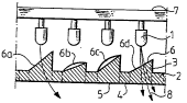
The common disc 2 as shown in figure l has a flat outer surface
facing du...lwc:~ds in the figure. At the disc and protruding
upwards from its surface are~several prisms 3 having r~17~
cross SF~rt~mn~:, me number of prisms and there positions at the
disc may vary due to the application. One example of a design
is a disc with an outer ~ of about 200 mm. At this disc
thOEe are 260 prisms, each having an outer ~ of ahout 8
mm.
The disc and the prisms may ~e made from the same or different
materials. Preferrably they are made as one piece from
poly~Lbul~aLt:~ which has properties as required in many
applicationS regarding index of reiraction, light tr~?n~cF21nn
and: ' 'r,~1 ~L~ LII. Another pr,sc~hlP ' '~ L is a disc
from a freely choosen matOEial having a numbOE of holes which
w~ ls to the number of prisms and a separate prism
``~":`
: .,j
~1 ~5597
inserted into each hole.
Figure 2 shows a cross section of a part of the disc with
prisms, four of which are shown in the figure, and with light
sources connected with the prisms. These are light emitting
diodes 1 each of which emits a wel~ ~~ L~ d light beam.
The spread of the light beam is often about 2-4 from the
centre axis of the diode. The light beam is directed onto the
oblique surface 6 of each prism and is refractea by this
surf ace . Thereupon the light beam passes through the prism and
is again refracted by the outer surface 5, which may be common
with the outer surfaoe 4 of the disc. For the surface which is
designated 6a also the outermost light is shown and it i5 seen
that all of the emitted light passes through the prism. Only
;nc;gn;fir;int quantities of stray light finds itsel other
paths .
The obli~ue surfaces 6 of each prism may be varied in respect
of both the angle at the centre axis of the prism and the
direction of the surface. In the figure the surfaoes 6a and 6d
have the same direction but different angles, while the
surfaces 6b and 6c have a somewhat different direction.
One example of a desired light pattern is shown in figure 3,
which in the form of a diagram shows the desired light ~ L~::ll
in a vertical plane at a certain distance from the lightning
device. The ~ ular, full lines indicated the desired
values and the broken i~g~ ~ly shaped lines show the results
of a metering of the strength of the light emitted from a
devioe according to the invention.
Fi~ure 4a-4c shows dii'ferent designs of the prisms and the
corr~sprm-l~ns disc. Preferrably the prisms and the disc are
made as one unit by in~ection molding of polymer, where
polycarbonate has turnea out to have the most suitable
conbination of properties. The ol~lique surface of the prism
touches the inner surface of the disc and then ~ Lude~
.
~ . y~
~ .
5 2185597
_
therefrom, so that there is no pit or the like in the un~ t.
A3 ternatively the the disc and prisms unit may be L)Luduc~ d by
drilling holes into an all over flat disc Wll~ LC:U~U~I individual
prisms are plac~d in these holes. The prisms may then be of
different size as shown in figures 4b and 4c. The last
mentioned ' '~ L will ~L~L~LLCIbly be ~sed only when a very
small number o identical devices shall be pro~ PA and the
costs for making a mould or adaption of an existing mould for
injection l~ln~ are too high. When making these moulds it is
preferred that the obligue 5uL Lc.~ o the prisms are formed on
the surfaces of small, .-J l,. .J.-~hle parts of the mould_ In this
way changes and adaptions are poccthlP easily and at a much
lower cost than i the ,~ tP mould would have to be
replaced. The rP~lA-P~h1~ details o the mould are controlled
in some way, e. g. by means of a flattened surface, so that
they can t freely be turned around there axis when they are
mounted into the mould. This also applies to individual prisms
when these are made as inserts into holes in a common- disc.
The invention makes it pnsc~hlf~ to obtain a desired light
pattern with much i n~rc~Acp(l precision. Adj u~; L~, as desired
are easily made and e g ~eft and right designs are easily
obtainable. One plate with light emitting diodes may produce
different light ~L~L1-S which may be .~.. I,i....~._A and adapted to
~ hAn5~ n ~ conditions .