Language selection

Search

Patent 2185633 Summary

Third-party information liability

Some of the information on this Web page has been provided by external sources. The Government of Canada is not responsible for the accuracy, reliability or currency of the information supplied by external sources. Users wishing to rely upon this information should consult directly with the source of the information. Content provided by external sources is not subject to official languages, privacy and accessibility requirements.

Claims and Abstract availability

Any discrepancies in the text and image of the Claims and Abstract are due to differing posting times. Text of the Claims and Abstract are posted:

  • At the time the application is open to public inspection;
  • At the time of issue of the patent (grant).
(12) Patent Application: (11) CA 2185633
(54) English Title: CATERPILLAR TRACK SHOE
(54) French Title: PATIN DE CHENILLE
Status: Deemed Abandoned and Beyond the Period of Reinstatement - Pending Response to Notice of Disregarded Communication
Bibliographic Data
(51) International Patent Classification (IPC):
  • A63C 17/10 (2006.01)
(72) Inventors :
  • SHYR, CHORNG RONG (Taiwan, Province of China)
  • CHENG, MING CHON (Taiwan, Province of China)
  • SHYR, CHORNG RONG (Taiwan, Province of China)
(73) Owners :
  • CHORNG RONG SHYR
  • MING CHON CHENG
  • CHORNG RONG SHYR
(71) Applicants :
(74) Agent: LAVERY, DE BILLY, LLP
(74) Associate agent:
(45) Issued:
(22) Filed Date: 1996-09-16
(41) Open to Public Inspection: 1998-03-17
Availability of licence: N/A
Dedicated to the Public: N/A
(25) Language of filing: English

Patent Cooperation Treaty (PCT): No

(30) Application Priority Data: None

Abstracts

English Abstract


A caterpillar track shoe including a shoe having a
plurality of screw holes in the sole; a caterpillar track type driving
mechanism fastened to the screw holes of the shoe and controlled
to move the shoe on a piece of land through a toe-controlled switch
in the shoe and a selector switch on the base frame of the driving
mechanism, the driving mechanism including a DC motor, a battery
power supply, a caterpillar track assembly, and a gear box coupled
between the DC motor and the drive wheel of the caterpillar track
assembly.


French Abstract

Patin de chenille comportant des trous de vis sur la semelle; un mécanisme d'entraînement de type chenille fixé aux trous de vis du patin et réglé de manière à faire bouger le patin sur le sol au moyen d'un interrupteur à commande au pied se trouvant dans le patin; un commutateur sélecteur situé sur l'ossature de base du mécanisme d'entraînement. Ce dernier comprend un moteur à courant continu, une batterie d'alimentation, une chenille et une boîte d'engrenage fixée entre le moteur à courant continu et la roue motrice de la chenille.

Claims

Note: Claims are shown in the official language in which they were submitted.

What the invention claimed is:
1. A caterpillar track shoe comprising:
a shoe having a plurality of screw holes in a sole thereof;
a caterpillar track type driving mechanism fastened to the
screw holes of said shoe and controlled to move said shoe on a
piece of land, said caterpillar track type driving mechanism
comprising a base frame fastened to the screw holes of said shoe, a
battery box mounted within the base frame to hold a rechargeable
battery, a motor mounted in said base frame and electrically
connected to said rechargeable battery by an electric circuit, a gear
box coupled to said motor, a drive wheel assembly transversely
mounted on said base frame at one end and turned by said motor
through said gear box, an idling wheel assembly transversely
mounted on said base frame at an opposite end and turned by said
drive wheel assembly through two symmetrical caterpillar tracks,
two symmetrical rows of tracker rollers respectively mounted on
said base frame at two opposite sides between said drive wheel
assembly and said idling wheel assembly, and two caterpillar
tracks respectively and bilaterally mounted around said drive
wheel assembly, said tracker rollers, and said idling wheel
assembly;
first switch means mounted on the base frame of said

caterpillar track type driving mechanism on the outside, and
shifted between two positions to turn on/off said motor;
second switch means mounted in said shoe, and adapted for
turning on said motor when said first switch means cuts off power
supply from said motor.

Description

Note: Descriptions are shown in the official language in which they were submitted.


~r~
,) V
CATERPILLAR TRACK SHOE
BACKGROUND OF THE INVENTION
The present invention relates to shoes, and relates more
specifically to a caterpillar track shoe which is designed for use in
5 carrying and moving the user in the snow or a piece of sandy land.
A variety of shoes and bootsj for example ice climbing
boots, touring boots, ski boots, ice skates, fencing shoes, boxing
shoes, running shoes, hockey skates, football shoes, etc., have been
disclosed for different purposes, and have appeared on the market.
10 llowever, there are no any shoes designed for moving the user on a
piece of sandy land.
SUMMARY OF THE INVENTION
The present invention provides a shoe which is practical
for moving the user on the snow as well as a piece of sandy land.
15 According to the preferred embodiment of the present invention,
the caterpillar track shoe comprises a shoe having a plurality of
screw holes in the sole, a caterpillar track type driving mechanism
fastened to the screw holes of the shoe and controlled to move the
shoe on a piece of land, the caterpillar track type driving
20 mechanism comprising a base frame fastened to the screw holes of
the shoe, a battery box mounted within the base frame to hold a
rechargeable battery, a motor mounted in the base frame and

~ 2185~3~
electrically connected to the rechargeable battery by an electric
circuit and controlled by a toe-controlled switch in the shoe and a
selector switch on the base frame, a gear box coupled to the motor,
a drive wheel assembly transversely mounted on the base frame at
one end and turned by the motor through the gear box, an idling
wheel assembly transversely mounted on the base frame at an
opposite end and turned by the drive wheel assembly through two
symmetrical caterpillar tracks, two symmetrical rows of tracker
rollers respectively mounted on the base frame at two opposite
sides between the drive wheel assembly and the idling wheel
assembly, and two caterpillar tracks respectively and bilaterally
rnounted around the drive wheel assembly, the tracker rollers, and
the idling wheel assembly.
BRIEF DESCRIT'TION OF THE DRAWINGS =
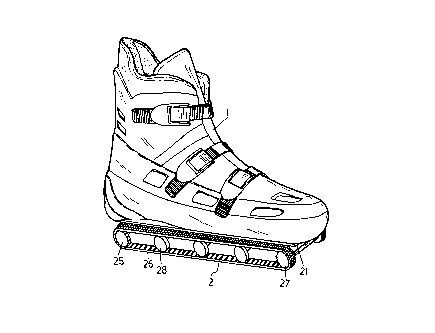
Fig. 1 is an elevational view of a caterpillar track shoe
according to the present invention; and
Fig. 2 is an exploded view of the caterpillar track shoe
shown in Figure 1.
DETAILED DESCRIPTTON OF THE PREFERRED EMBODIMENT
Referring to Figures 1 and 2, a caterpillar track shoe in
accordance with the present invention, is adapted for carrying and
moving the user on a snow-covered ground or in a sandy piece of

21~SC33
land, comprised of a shoe 1, and a caterpillar track type driving
mechanism 2. The shoe 1 has screw holes 11 in the sole to which
the caterpillar track type driving mechanism 2 is fastened, and a
switch (not shown) adapted for controlling the operation of the
5 caterpillar track type driving mechanism 2 through the big (first)
toe. The track type driving mechanism 2 comprises a base frame 21,
a battery box 23 mounted within the base frame 21 in the middle to
hold a rechargeable battery 22, a motor 24 mounted in the base
frame 21 at a suitable location for example at the rear side behind
10 the battery box 23, a gear box 230 coupled to the motor 24, a drive
wheel assembly 25 transversely mounted on the base frame 21 at
the rear side and turned by the motor 24 through the gear box 230,
an idling wheel assembly 27 transversely mounted on the base
frame 21 at the front side and turned by the drive wheel assembly
15 25 through two symmetrical caterpillar tracks, two symmetrical
rows of tracker rollers 28 respectively mounted on the base frame
21 at two opposite sides between the drive wheel assembly 25 and
the idling wheel assembly 27, and two caterpillar tracks 26
respectively and bilaterally mounted around the drive wheel
20 assembly 25, the tracker rollers 28, and the idling wheel assembly
27. The base frame 21 further has a plurality of mounting holes 29
respectively fastened to the screw holes 11 in the sole of the shoe 1

2185~3~
~
by respective screws. A selector switch 20 is mounted on the base
frame 21 on the outside and connected to the electric circuit of the
rechargeable battery 22.
When assembled, the battery power of the rechargeable
S battery 22 is provided to the motor 24 through the switch in the
shoe I via the selector switch 20. When the selector switch 20 is
shifted to a first position, the motor 24 is constantly turned on;
when the selector switch 20 is shifted to a second position, the
nnotor 24 can then be turned on/off through the switch in the shoe
10 11. When the motor 24 is turned on, the drive wheel assembly 2S is
turned to rotate the caterpillar tracks 26, thereby causing the shoe 1
to be moved on a piece of snow-covered or sandy land.
While only one embodiment of the present invention has
been shown and described, it will be understood that various
15 modifications and changes could be made without departing from
the spirit and scope of the invention disclosed. For example, brake
means may be installed, and controlled to stop the shoe from
moving.

Representative Drawing
A single figure which represents the drawing illustrating the invention.
Administrative Status

2024-08-01:As part of the Next Generation Patents (NGP) transition, the Canadian Patents Database (CPD) now contains a more detailed Event History, which replicates the Event Log of our new back-office solution.

Please note that "Inactive:" events refers to events no longer in use in our new back-office solution.

For a clearer understanding of the status of the application/patent presented on this page, the site Disclaimer , as well as the definitions for Patent , Event History , Maintenance Fee  and Payment History  should be consulted.

Event History

Description Date
Inactive: Cover page published 1999-09-30
Time Limit for Reversal Expired 1999-09-16
Application Not Reinstated by Deadline 1999-09-16
Deemed Abandoned - Failure to Respond to Maintenance Fee Notice 1998-09-16
Application Published (Open to Public Inspection) 1998-03-17

Abandonment History

Abandonment Date Reason Reinstatement Date
1998-09-16
Owners on Record

Note: Records showing the ownership history in alphabetical order.

Current Owners on Record
CHORNG RONG SHYR
MING CHON CHENG
CHORNG RONG SHYR
Past Owners on Record
None
Past Owners that do not appear in the "Owners on Record" listing will appear in other documentation within the application.
Documents

To view selected files, please enter reCAPTCHA code :


To view images, click a link in the Document Description column. To download the documents, select one or more checkboxes in the first column and then click the "Download Selected in PDF format (Zip Archive)" or the "Download Selected as Single PDF" button.

List of published and non-published patent-specific documents on the CPD .

If you have any difficulty accessing content, you can call the Client Service Centre at 1-866-997-1936 or send them an e-mail at CIPO Client Service Centre.


Document
Description 
Date
(yyyy-mm-dd) 
Number of pages   Size of Image (KB) 
Cover Page 1996-12-23 1 13
Description 1996-12-23 4 130
Abstract 1996-12-23 1 15
Drawings 1996-12-23 2 58
Claims 1996-12-23 2 41
Cover Page 1998-04-06 1 44
Cover Page 1999-09-29 1 44
Representative drawing 1998-03-25 1 14
Reminder of maintenance fee due 1998-05-20 1 111
Courtesy - Abandonment Letter (Maintenance Fee) 1998-10-14 1 184