Sélection de la langue

Search

Sommaire du brevet 2185633 

Énoncé de désistement de responsabilité concernant l'information provenant de tiers

Une partie des informations de ce site Web a été fournie par des sources externes. Le gouvernement du Canada n'assume aucune responsabilité concernant la précision, l'actualité ou la fiabilité des informations fournies par les sources externes. Les utilisateurs qui désirent employer cette information devraient consulter directement la source des informations. Le contenu fourni par les sources externes n'est pas assujetti aux exigences sur les langues officielles, la protection des renseignements personnels et l'accessibilité.

Disponibilité de l'Abrégé et des Revendications

L'apparition de différences dans le texte et l'image des Revendications et de l'Abrégé dépend du moment auquel le document est publié. Les textes des Revendications et de l'Abrégé sont affichés :

  • lorsque la demande peut être examinée par le public;
  • lorsque le brevet est émis (délivrance).
(12) Demande de brevet: (11) CA 2185633
(54) Titre français: PATIN DE CHENILLE
(54) Titre anglais: CATERPILLAR TRACK SHOE
Statut: Réputée abandonnée et au-delà du délai pour le rétablissement - en attente de la réponse à l’avis de communication rejetée
Données bibliographiques
(51) Classification internationale des brevets (CIB):
  • A63C 17/10 (2006.01)
(72) Inventeurs :
  • SHYR, CHORNG RONG (Taïwan, Province de Chine)
  • CHENG, MING CHON (Taïwan, Province de Chine)
  • SHYR, CHORNG RONG (Taïwan, Province de Chine)
(73) Titulaires :
  • CHORNG RONG SHYR
  • MING CHON CHENG
  • CHORNG RONG SHYR
(71) Demandeurs :
(74) Agent: LAVERY, DE BILLY, LLP
(74) Co-agent:
(45) Délivré:
(22) Date de dépôt: 1996-09-16
(41) Mise à la disponibilité du public: 1998-03-17
Licence disponible: S.O.
Cédé au domaine public: S.O.
(25) Langue des documents déposés: Anglais

Traité de coopération en matière de brevets (PCT): Non

(30) Données de priorité de la demande: S.O.

Abrégés

Abrégé français

Patin de chenille comportant des trous de vis sur la semelle; un mécanisme d'entraînement de type chenille fixé aux trous de vis du patin et réglé de manière à faire bouger le patin sur le sol au moyen d'un interrupteur à commande au pied se trouvant dans le patin; un commutateur sélecteur situé sur l'ossature de base du mécanisme d'entraînement. Ce dernier comprend un moteur à courant continu, une batterie d'alimentation, une chenille et une boîte d'engrenage fixée entre le moteur à courant continu et la roue motrice de la chenille.


Abrégé anglais


A caterpillar track shoe including a shoe having a
plurality of screw holes in the sole; a caterpillar track type driving
mechanism fastened to the screw holes of the shoe and controlled
to move the shoe on a piece of land through a toe-controlled switch
in the shoe and a selector switch on the base frame of the driving
mechanism, the driving mechanism including a DC motor, a battery
power supply, a caterpillar track assembly, and a gear box coupled
between the DC motor and the drive wheel of the caterpillar track
assembly.

Revendications

Note : Les revendications sont présentées dans la langue officielle dans laquelle elles ont été soumises.


What the invention claimed is:
1. A caterpillar track shoe comprising:
a shoe having a plurality of screw holes in a sole thereof;
a caterpillar track type driving mechanism fastened to the
screw holes of said shoe and controlled to move said shoe on a
piece of land, said caterpillar track type driving mechanism
comprising a base frame fastened to the screw holes of said shoe, a
battery box mounted within the base frame to hold a rechargeable
battery, a motor mounted in said base frame and electrically
connected to said rechargeable battery by an electric circuit, a gear
box coupled to said motor, a drive wheel assembly transversely
mounted on said base frame at one end and turned by said motor
through said gear box, an idling wheel assembly transversely
mounted on said base frame at an opposite end and turned by said
drive wheel assembly through two symmetrical caterpillar tracks,
two symmetrical rows of tracker rollers respectively mounted on
said base frame at two opposite sides between said drive wheel
assembly and said idling wheel assembly, and two caterpillar
tracks respectively and bilaterally mounted around said drive
wheel assembly, said tracker rollers, and said idling wheel
assembly;
first switch means mounted on the base frame of said

caterpillar track type driving mechanism on the outside, and
shifted between two positions to turn on/off said motor;
second switch means mounted in said shoe, and adapted for
turning on said motor when said first switch means cuts off power
supply from said motor.

Description

Note : Les descriptions sont présentées dans la langue officielle dans laquelle elles ont été soumises.

~r~
,) V
CATERPILLAR TRACK SHOE
BACKGROUND OF THE INVENTION
The present invention relates to shoes, and relates more
specifically to a caterpillar track shoe which is designed for use in
5 carrying and moving the user in the snow or a piece of sandy land.
A variety of shoes and bootsj for example ice climbing
boots, touring boots, ski boots, ice skates, fencing shoes, boxing
shoes, running shoes, hockey skates, football shoes, etc., have been
disclosed for different purposes, and have appeared on the market.
10 llowever, there are no any shoes designed for moving the user on a
piece of sandy land.
SUMMARY OF THE INVENTION
The present invention provides a shoe which is practical
for moving the user on the snow as well as a piece of sandy land.
15 According to the preferred embodiment of the present invention,
the caterpillar track shoe comprises a shoe having a plurality of
screw holes in the sole, a caterpillar track type driving mechanism
fastened to the screw holes of the shoe and controlled to move the
shoe on a piece of land, the caterpillar track type driving
20 mechanism comprising a base frame fastened to the screw holes of
the shoe, a battery box mounted within the base frame to hold a
rechargeable battery, a motor mounted in the base frame and

~ 2185~3~
electrically connected to the rechargeable battery by an electric
circuit and controlled by a toe-controlled switch in the shoe and a
selector switch on the base frame, a gear box coupled to the motor,
a drive wheel assembly transversely mounted on the base frame at
one end and turned by the motor through the gear box, an idling
wheel assembly transversely mounted on the base frame at an
opposite end and turned by the drive wheel assembly through two
symmetrical caterpillar tracks, two symmetrical rows of tracker
rollers respectively mounted on the base frame at two opposite
sides between the drive wheel assembly and the idling wheel
assembly, and two caterpillar tracks respectively and bilaterally
rnounted around the drive wheel assembly, the tracker rollers, and
the idling wheel assembly.
BRIEF DESCRIT'TION OF THE DRAWINGS =
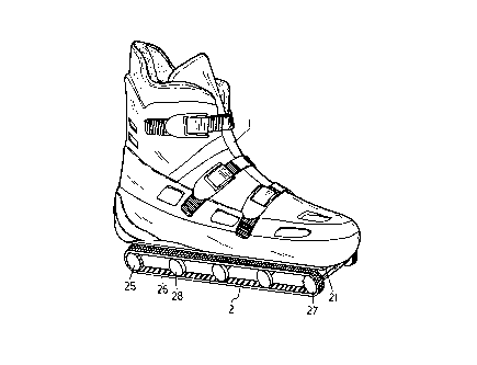
Fig. 1 is an elevational view of a caterpillar track shoe
according to the present invention; and
Fig. 2 is an exploded view of the caterpillar track shoe
shown in Figure 1.
DETAILED DESCRIPTTON OF THE PREFERRED EMBODIMENT
Referring to Figures 1 and 2, a caterpillar track shoe in
accordance with the present invention, is adapted for carrying and
moving the user on a snow-covered ground or in a sandy piece of

21~SC33
land, comprised of a shoe 1, and a caterpillar track type driving
mechanism 2. The shoe 1 has screw holes 11 in the sole to which
the caterpillar track type driving mechanism 2 is fastened, and a
switch (not shown) adapted for controlling the operation of the
5 caterpillar track type driving mechanism 2 through the big (first)
toe. The track type driving mechanism 2 comprises a base frame 21,
a battery box 23 mounted within the base frame 21 in the middle to
hold a rechargeable battery 22, a motor 24 mounted in the base
frame 21 at a suitable location for example at the rear side behind
10 the battery box 23, a gear box 230 coupled to the motor 24, a drive
wheel assembly 25 transversely mounted on the base frame 21 at
the rear side and turned by the motor 24 through the gear box 230,
an idling wheel assembly 27 transversely mounted on the base
frame 21 at the front side and turned by the drive wheel assembly
15 25 through two symmetrical caterpillar tracks, two symmetrical
rows of tracker rollers 28 respectively mounted on the base frame
21 at two opposite sides between the drive wheel assembly 25 and
the idling wheel assembly 27, and two caterpillar tracks 26
respectively and bilaterally mounted around the drive wheel
20 assembly 25, the tracker rollers 28, and the idling wheel assembly
27. The base frame 21 further has a plurality of mounting holes 29
respectively fastened to the screw holes 11 in the sole of the shoe 1

2185~3~
~
by respective screws. A selector switch 20 is mounted on the base
frame 21 on the outside and connected to the electric circuit of the
rechargeable battery 22.
When assembled, the battery power of the rechargeable
S battery 22 is provided to the motor 24 through the switch in the
shoe I via the selector switch 20. When the selector switch 20 is
shifted to a first position, the motor 24 is constantly turned on;
when the selector switch 20 is shifted to a second position, the
nnotor 24 can then be turned on/off through the switch in the shoe
10 11. When the motor 24 is turned on, the drive wheel assembly 2S is
turned to rotate the caterpillar tracks 26, thereby causing the shoe 1
to be moved on a piece of snow-covered or sandy land.
While only one embodiment of the present invention has
been shown and described, it will be understood that various
15 modifications and changes could be made without departing from
the spirit and scope of the invention disclosed. For example, brake
means may be installed, and controlled to stop the shoe from
moving.

Dessin représentatif
Une figure unique qui représente un dessin illustrant l'invention.
États administratifs

2024-08-01 : Dans le cadre de la transition vers les Brevets de nouvelle génération (BNG), la base de données sur les brevets canadiens (BDBC) contient désormais un Historique d'événement plus détaillé, qui reproduit le Journal des événements de notre nouvelle solution interne.

Veuillez noter que les événements débutant par « Inactive : » se réfèrent à des événements qui ne sont plus utilisés dans notre nouvelle solution interne.

Pour une meilleure compréhension de l'état de la demande ou brevet qui figure sur cette page, la rubrique Mise en garde , et les descriptions de Brevet , Historique d'événement , Taxes périodiques et Historique des paiements devraient être consultées.

Historique d'événement

Description Date
Inactive : Page couverture publiée 1999-09-30
Le délai pour l'annulation est expiré 1999-09-16
Demande non rétablie avant l'échéance 1999-09-16
Réputée abandonnée - omission de répondre à un avis sur les taxes pour le maintien en état 1998-09-16
Demande publiée (accessible au public) 1998-03-17

Historique d'abandonnement

Date d'abandonnement Raison Date de rétablissement
1998-09-16
Titulaires au dossier

Les titulaires actuels et antérieures au dossier sont affichés en ordre alphabétique.

Titulaires actuels au dossier
CHORNG RONG SHYR
MING CHON CHENG
CHORNG RONG SHYR
Titulaires antérieures au dossier
S.O.
Les propriétaires antérieurs qui ne figurent pas dans la liste des « Propriétaires au dossier » apparaîtront dans d'autres documents au dossier.
Documents

Pour visionner les fichiers sélectionnés, entrer le code reCAPTCHA :


Pour visualiser une image, cliquer sur un lien dans la colonne description du document. Pour télécharger l'image (les images), cliquer l'une ou plusieurs cases à cocher dans la première colonne et ensuite cliquer sur le bouton "Télécharger sélection en format PDF (archive Zip)" ou le bouton "Télécharger sélection (en un fichier PDF fusionné)".

Liste des documents de brevet publiés et non publiés sur la BDBC .

Si vous avez des difficultés à accéder au contenu, veuillez communiquer avec le Centre de services à la clientèle au 1-866-997-1936, ou envoyer un courriel au Centre de service à la clientèle de l'OPIC.


Description du
Document 
Date
(aaaa-mm-jj) 
Nombre de pages   Taille de l'image (Ko) 
Page couverture 1996-12-23 1 13
Description 1996-12-23 4 130
Abrégé 1996-12-23 1 15
Dessins 1996-12-23 2 58
Revendications 1996-12-23 2 41
Page couverture 1998-04-06 1 44
Page couverture 1999-09-29 1 44
Dessin représentatif 1998-03-25 1 14
Rappel de taxe de maintien due 1998-05-20 1 111
Courtoisie - Lettre d'abandon (taxe de maintien en état) 1998-10-14 1 184