Note: Descriptions are shown in the official language in which they were submitted.
2 1 85685
~;.T T~
Zoned lens
The invention relates to a zoned lens.
Lenses are in this case generally understood to be both refractive lenses and
diffractive lenses (for example, Fresnel zone plates). A diaphragm provided
with a small hole can also be provided with effective powers (effective
refractive powers), as described with reference to the drawings. Optical
10 elements with a zero nominal power but with a limited aperture such as, for
example, circular or annular plates with parallel front and rear surfaces can
therefore also be understood here as "lenses".
Different zones of a lens are represented by areas of a lens which can be
15 differentiated by physical properties, wherein between the zones the physicalproperties alter very rapidly or abruptly over a relatively small area. In
particular, step-like sudden changes in the thickness of the lens material beingused. for example, steps on the front or rear surface of the lens, delimit
different zones of a lens. The use of different lens materials in different areas
20 of the lens also results in a zoned lens in the present sense. The geometrical
arrangement of the different zones can be configured in many different ways.
For example, a central circular zone can be provided, to which outer
concentric annular zones are adjacent. The surface areas of the different
zones can be the same or different.
The object of the invention is to provide a zoned lens with novel optical
properties. This is achieved according to the invention in that it comprises at
least two adjacent zones, wherein the differences in the optical path lengths
between an object point and an image point, of light rays passing through
30 these two adjacent zones of the lens, are at least equal to half the coherence
2 1 856~5
_ 2
length of the light used, preferably at least equal to the coherence length of
the light used. If there are optical materials with different refractive indices in
the different zones, in such a configuration it can advantageously be provided
that any two rays parallel to the axis through two adjacent zones pass through
5 optical path lengths within the lens which differ by at least the coherence
length. If adjacent zones are made from the same lens material, the optical
path lengths of any two rays parallel to the axis through the two adjacent
zones have to differ by at least CL nC/(nc-ni), wherein CL is the coherence
length of the light used, nc is the refractive index of the lens material and nj is
10 the refractive index of the medium surrounding the lens. The values nc = 1.5
and nj = 1 produce, for example, 3 CL. This condition is satisfied when, for
example, steps of a height resulting from CU(nc-ni) are provided between the
zones. The values selected for nc and ni and the coherence length of, for
example, 2 micrometres, produces a step height of 4 micrometres.
In the case where the differences in the optical path lengths of the light rays
which pass through adjacent zones of the lens between an object point and
an image point are at least equal to the coherence length of the light used.
there is no interference of the light rays passing through the adjacent zones.
20 as will be described in more detail with reference to the drawings, whereby in
various applications advantages can be obtained compared to conventional
lenses. For example, in bifocal lenses disturbing interferences between the
areas with different focal lengths can be eliminated.
25 If the steps are configured so that the optical path length differences of the
light rays through adjacent zones between an object point and an image point
are shorter than the coherence length but at least equal to half the coherence
length of the light used, the interference of the light rays passing through
adjacent zones is reduced but not completely suppressed, which may be
30 sufficient for some applications. Zoned lenses with such reduced steps are
thus also the subject-matter of the invention.
2 1 85685
._ 3
In an embodiment of the invention it is provided that adjacent zones of the
lens have a different thickness, wherein steps are provided between the
zones. The step height between adjacent zones of the lens has to be at least
IA2/(l~A(nc-n;)) 1, wherein 1 is the average wavelength of the light used, ~A is5 the half-value width of the wavelength distribution of the light used, nc is the
refractive index of the lens material, and nj is the refractive index of the
medium adjacent to the lens. The coherence length is given by CL = ~2/~
When visible light with a coherence length in the region of approximately 1 -
10 ~m is used, the step height, measured in micrometres. between adjacent
10 zones of the lens has to be at least 5/1(nC-n;) 1, wherein nc is the refractive
index of the lens material and ni is the refractive index of the medium adjacentto the lens. Advantageously, a step height of at least 3 micrometres,
preferably of at least 10 micrometres, is provided. As the standard lens
materials have a refractive index of approximately 1.5, and as the light re-
15 emiKed from subjects illuminated with "white" light has coherence lengthswhich are normally in the region of 3 I~m, however seldom above 5 I~m,
interference between the different zones can be effectively eliminated with
such a step height.
20 Such a zoned lens according to the invention can be configured, for example,
such that a central circular zone is provided and around it are adjoining
concentric annular zones, wherein the surface areas of all the zones is the
same. Such a zoned lens can satisfy the otherwise contradicting
requirements of having a wide distribution of the effective power and a high
25 intensity of light allowed to pass through, as described in more detail with
reference to the drawings. In order to eliminate scattered light from the lateral
step surfaces between the zones, in this embodiment of the invention it is
advantageously provided that the lateral surfaces of the steps between the
zones are provided with a light absorbing material.
The optical path length of a light ray from an object point through the lens to
2 1 85685
a conjugated image point belonging to this object point is composed of the two
values outside the lens and the value within the lens. With the precautions
described above, the optical path lengths of light rays through two adjacent
zones differ by at least the coherence length. If - as in the case of multifocal5 lenses - there are several image points conjugated to one object point, the
optical path lengths through adjacent zones have to measured between the
object point and always the same image point. Any of the available
conjugated image points, which may be real or virtual, can be used for this
purpose.
The determination of a conjugated image point belonging to a specific object
point is known prior art. Examples of methods for implementing this are,
howeven briefly described again in the description of the drawings.
15 Further advantages and details of the invention will be described in the
following with reference to the attached drawings.
These show. in
0 Fig.1a and 1b, schematic representations of the ray angle of radiating
surfaces,
Fig.2 a distribution of the effective power of a lens,
Fig.3 the dependency of the half-value width of the distribution of the
effective power upon the lens aperture,
25 Fig.4 the dependency of the half-value width of the effective power,
normalised to the wavelength of the light, upon the lens surface,
Fig.5 distributions of effective powers with different lens apertures,
Fig.6 a comparison of the interference pattern of a circular surface with
an annular surface with the same surface area,
30 Fig.7 reflectance spectra of difference items,
Fig.8a an embodiment of the invention,
2 1 85685
Fig.8b a second embodiment of the invention,
Fig.9 a third embodiment of the invention,
Fig.10 a contact lens according to the invention,
Fig.11 an auxiliary drawing showing the construction of a lens,
5 Fig.12 the distribution of the effective powers of a lens according to the
invention compared to a conventional lens with a surface ten times
smaller,
Fig.13a and 13b, distributions of the effective powers of bifocal lenses
without and with interference between the zones,
10 Fig. 14 a distribution of the effective powers of a lens made from birefringent material,
Fig. 15 a further embodiment of the invention,
Fig.16 a comparison of the effective power of a conventional lens with that
of a system composed of a conventional lens and a lens according
to the invention,
Fig.17 to 20, further embodiments of the invention,
Fig.21 a comparison of the effective powers of different refractive bifocal
zoned lenses, both conventional and according to the invention,
Fig.22 the dependency of the optical path lengths upon the distance apart
of the light rays from the centre point of the lens for the image point
for a power of -5 dioptres,
Fig.23 a further embodiment of the invention,
Fig.24 the dependency of the optical path length differences upon the
distance of the rays from the central point of the lens in the case of
a conventional refractive bifocal zoned lens,
Fig.25 the dependency of the optical path length upon the distance of the
rays from the central point of the lens of a bifocal zoned lens
according to the invention at an effective power of 3.75 dioptres.
30 It is known that the ray width of the light from a radiating surface is greater the
smaller the radiating surface. This physical fact can be explained by
2~ 85685
examination of interference: Fig. 1a shows in a schematic manner a small
surface 1, which emits, for example, coherent light 2, wherein all the partial
waves transmitted may have identical phases at the location of the emission.
The ray width aA at which the initially destructive interference between the
5 marginal rays or waves occurs, is greater than the width aB with the same
conditions as in Fig. 1b. It can be directly concluded from this that, for
example, a lens with a smaller aperture has a greater depth of field than a
lens with a larger aperture.
10 A practical application of this fact is represented by so-called stenopaic
spectacles: According, for example, to Graefe-Saemisch: Handbuch der
gesamten Augenheilkunde [Handbook of General Optical Medicine], Wilhelm
Engelmann publications, Leipzig 1910, page 178, stenopaic spectacles are
"characterised by those devices wherein a greater focus of the retinal image
15 (comment: optically refractive devices) is not caused by changing the ray path,
but instead in that attempts are made to reduce the dimension of the circle of
divergence by suitable apertures, that is to say by the limitation of the incident
ray cluster. The simplest form of such spectacles is a diaphragm provided
with a very small hole".
The disadvantages of such stenopaic spectacles are essentially apparent in
the reduction of the light intensity and in the restriction of the field of vision;
further, the capacity for resolution and contrast of optical devices generally
reduces with increasing depth of field. With different optical applications. the25 reduction of the contrast and resolution is acceptable, however.
The disadvantage of the narrowed field of vision can be alleviated by bringing
the hole closer to the eye. that is to say by configuring the "spectacle" as a
contact lens (or as an intra-ocular lens). The disadvantage of the reduced
30 light intensity is occasionally countered by having several adjacent holes (see
Graefe-Saemisch, loc.cit). With adjacent holes, however, interference is
2 1 85685
_ 7
produced between the light waves from the different holes, which
disadvantageously affects the imaging quality.
With the present invention! a radiating surface can be designed so that each
5 individual partial area of this surface emits light practically unaffected by the
other partial areas, so that the interference patterns behind the individual
partial areas exist independently of one another, and consequently do not
interfere with the wave trains coming from different partial areas. In this way,for example. the light intensity of stenopaic spectacles or lenses can be
10 increased substantially without reducing the optical advantages produced by
the restriction of the incident light ray clusters to very small apertures.
Furthermore, with the present invention, lenses with a relatively large aperturecan be manufactured which have the depth of field of lenses with a very small
aperture, which however allow substantially greater light intensities to pass
15 through than the corresponding lenses with a small aperture. Further, with the
present invention devices can be produced with which conventional lenses
with a large aperture can be given the optical characteristics of lenses with
small apertures. Such "stenopaic lenses" with a large aperture and light
intensity can be used in many ways in optical apparatuses and optical and
20 ophthalmic devices. For example, in this way ophthalmic viewing aids can be
manufactured which serve to correct geriatric vision and/or for the correction
of astigmatism. Further, it is also possible with the present invention to
manufacture bifocal or multifocal zoned lenses in which interference between
the individual zones is suppressed. It is also possible to manufacture bifocal
25 or multifocal lenses in which only zones with the same nominal power can
interfere. Lastly, it is possible with the present invention to manufacture
Fresnel zone plates which have substantially double the light yield of
conventional Fresnel zone plates.
30 Figure 2 shows the distribution of the effective power of a lens of 1mm
diameter and nominally 4 dioptres, that is to say the intensity of the light 2 is
2 1 85685
plotted with respect to the effective power De,t. As can be seen, because of
this small aperture of 1 mm, this lens provides a wide spectrum of effective
power. As a measurement of the width of the distribution of the power, the
half-value width ~P of the distribution is assumed; for the lens evaluated in
5 Fig.2, the half-value width (for a light wave length of 560 mm) is approximately
4 dioptres.
The calculation of the distribution of the effective power of a lens - as shown.for example, in Fig. 2 - can be done in different ways. Two methods for this
10 are described briefly hereafter:
Method 1:
j connecting rays from an object point O located on the axis of the lens g
metres in front of the front surface of the lens are drawn to j points evenly
15 distributed on the front surface of the lens. Then, from each of the j points on
the front surface k connecting lines are drawn to k points evenly distributed
on the rear surface of the lens. (With numerical evaluation, it makes sense
to place the j and k points in an orthogonal grid). Then the k points on the
rear surface are connected to an image point B located on the axis of the lens
20 b metres behind the lens (9 and b can also have negative values).
Thus there are altogether j k wave trains which connect the object point O to
the image point B. The optical path lengths Ljk between O and B are then
determined for each of these j k wave trains. The resulting amplitude in the
25 image point B then produces
Ares = Const. (~sin q)jk + ~COs q~jk); (Pjk (Ljk/A) 2n,
wherein A is the wavelength of the light. The summation has to be extended
to all the j's and k's. The intensity resulting in B is then A,3s2.
30 The associated "effective power" De~ is further given by
De~ = 1/9 + 1/b
2 1 85685
Distribution curves as shown in Fig. 2, are obtained by changing 9 or b; the
two values g and b can also be varied simultaneously.
Method 2:
As in method 1, an object point O is connected to j evenly distributed points
on the front surface of the lens. These connecting lines then represent j light
rays, for which the law of refraction is used to obtain the j broken light rays
within the lens. The broken j light rays meet in j points on the rear surface of10 the lens; now each of these j points is connected to the point B. In this wayj wave trains are obtained between the points O and B and consequently Lj
different optical path lengths of the j wave trains. The resulting amplitude in
B is then given by
15 A'res = Const~ (~sin ~j + ~cos ~j) with ~j = (Lj/A)~2rT
The summation now has to be extended to all j wave trains.
The two methods give practically the same result, when summation takes
20 place over sufficient rays and points. As the complexity of the calculation is
substantially less with method 2, this method is to be preferred. The
characterisation of lenses set out hereafter is also done according to the
principles of method 2. To calculate different effective powers Det" the image
distance b can further be kept constant and only the object distance g varied
25 whereby the 1/r-loss of the amplitude does not have to be taken into account
explicitly.
According to the formula set out above for the effective power Det" it should
be noted that a given object width 9k iS connected to the conjugated image
30 width bk (or a given image width bk to the conjugated object width 9k)
approximately as follows.
2 1 85685
D = 1/gk + 1/bk
wherein D is the nominal power of the lens. This approximation is relevant for
thin lenses, in which the ~wo main planes practically coincide. Further, these
conditions are applicable only for lenses in air or in a vacuum. If the
5 conjugated values 9k and bk are used in the condition for the effective power
Detf, for thin lenses in a vacuum only, the nominai power is obtained. In other
cases the relationship given above (De~f = 1/9 + 1/b) represents a definition ofan "effective" power Det,.
10 If a medium with the refractive index ny is located in front of the lens, andbehind the lens a medium with the refractive index nh, the conjugated object
or image widths can be determined with the aid of calculation of the ray path
through the lens. With this, the deflections of the rays on the refracting lens
surfaces are calculated by means of Snell's law of refraction. In the case of
15 sphericaily curved lens surfaces, and small lens apertures, the basic
relationship
n1/a + n2/b = (n2 - n1)/r
can be used, wherein n1 is the refractive index in front, and n2 is the refractive
index at the rear of the refracting surface with the spherical radius r, and
20 wherein a and b are the distances measured in front of and behind the
refracting surface along a normal on the refracting surface. In each case, the
conjugated object and image widths can be determined for a light ray emitted
from an object point; further, with the aid of considerations set out here - andknown - a lens or a lens zone can be designed so that all light rays originating25 from the object point are broken at the same conjugated image point, see
below.
The dependency of t~ P of the distribution of the effective power upon the lens
aperture A (and the wavelength) is represented in Fig. 3. It is noted that this
30 half-value width is independent of the nominal power of the lens.
2 1 85685
11
Fig. 4 can be derived from the results of Fig. 3. As can be seen, the half-
value width ~ P of the power distribution can be given as a good approximation
of the function
l~P = A~0.0056/F
5 shown in Fig. 4 by a broken line, wherein ~P is the half-value width in
dioptres, A is the wavelength in nm and F is the radiating lens surface in mm2.
The reduction of the half-value width with an increasing lens surface can be
seen from the results in Fig. 5, in which the intensity I of the light normalised
10 on the lens surface F is plotted with respect to this effective power De~ for a
lens with a nominal power of four dioptres. The lens with an aperture A of
3.16 = ~/ 10 mm has a surface ten times larger than one with a diameter of
1 mm, the half-value width (and thereby the depth of field) of the larger lens
is correspondingly smaller.
In order to understand the present invention, it is now essential that the
interference pattern (7), depicted in Fig. 6 behind a circular radiating surface5, is the interference paKern (8) behind an annular surface 6 concentric to thiscircular surface, when the area of the circular surface 5 and of the annular
20 surface 6 is identical; this result can be derived, for example, directly from the
theory of the Fresnel zone plate.
To multiply the intensity, the circular surface is surrounded by as many
concentric annular surfaces as desired. In order to obtain the optical
25 properties of radiating surfaces with a small area, with a system using such
small surfaces the interference of the waves from the individual small surfaces
has to be prevented. The interference of waves from different partial areas
of a radiating surface differ by at least the coherence length of the emitted (or
re-emitted) light; the optical path lengths are measured from the location of
30 the light emission to the location of the interference or non-interference (image
point or potential image point).
21 85685
-- 12
As described in standard works (for example, Bergmann-Schafer, Optik
[Optics] pps 331 ff, Max Born, Berlin-Heidelberg, New York 1972, p. 1 11 ) two
light waves interfere with one another when the difference in their optical pathlength is smaller than the coherence length C.L. = A2/~A, wherein A is the
5 average wavelength and ~A is the half-value width of the wavelength
distribution of the spectrum transmitted by the light source. The coherence
length of "white light" is approximately 1 ~m (see Bergman-Schafer, loc.cit p.
333); this value is obtained directly by using A = 55 nm and ~A = 300 nm
(white light comprises a wavelength range of approximately 400 to 700 nm).
In optical and ophthalmic applications, as a rule light re-emitted from objects
is being dealt with. In Fig. 7 the re-emission spectra of blue car paint 10, theleaf in a bunch of roses 11 and of a yellow apple are shown. The coherence
lengths of these objects are 2 ,um, 3.6 ~m and 2.3 ~m. From these results it
15 can be concluded that the coherence lengths of the visible light emitted fromobjects seldom exceeds values of approximately 5 -10 ,um (in comparison,
laser light which is emitted in an extremely narrow wavelength range has
coherence lengths of many metres).
20 In order, for example, to now configure the individual zones of a lens so that
the light waves do not interfere behind the lens because of the different
zones, it is sufficient to configure the zones so that the optical path lengths of
the light rays associated with the light waves through the different zones have
differences of at least the coherence length. Such zoned lenses or optical
25 devices are hereinafter referred to as "coherence length corrected".
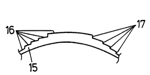
Fig. 8a shows a possible embodiment. The lens 15 is formed such that each
of its zones 16 has a nominally equal power (the nominal power is then the
power at which the distribution curve for the effective power is maximum; see
30 Fig. 2). The curvature of the front or rear surface of the zones 16 can be
calculated according to known lens formulae. Further, the zones 16 can be
2 1 85685
13
configured so that the optical path lengths of all the rays through a given zone16, measured from an object point passing through the zone 16 to the
conjugated image point corresponding to the nominal power (in the case of
negative lenses or zones 16, the image point is virtual), are exactly equal (the5 expression "aplanatic" is occasionally used for such lenses or lens zones).
The individual zones 16 of the lens are now of different thicknesses, so at the
borders between the zones there are steps 17. The height of the individual
steps 17 between the zones 16 must now be at least C.L.l(n1-nj), wherein n
is the refractive index of the medium adjacent to the lens 15 and n, is the
10 refractive index of the lens material, so that the differences in the optical path
lengths of the waves associated with the rays through the different zones 16
are greater than the coherence length of the light processed. If the axis of thelens represents, for example, the z-axis of a system of coordinates, the height
of the steps 17 is the absolute amount of the difference between the largest
15 z-coordinate of the front or rear surface of the one zone 16 and the smallestz-coordinate of the front or rear surface of the zone 16 bordering this zone 16.
The steps can, as already described, naturally be configured either on the
front surface or the rear surface of the lens, and embodiments in which both
20 lens surfaces are provided with steps are also possible. In order to avoid
scattered light from the lateral surfaces of the steps 17, they can be covered
with a light absorbing material. The steps between adjacent zones can also
be inclined and/or curved, so adjacent zones are connected not by cylindrical
walled surfaces, but instead by conical walls or barrel-shaped walls. Such
25 wall surfaces can themselves be considered as annular lenses with a smaller
total surface and very large absolute refractive power. The (slight) amount of
the light incident upon the wall surfaces compared to the total amount of light
incident upon the lens is then very much broken by these wall surfaces, and
occurs as background intensity. In this respect, these areas should not be
30 considered as "zones" of the zoned lens according to the invention, however,
but rather as transitional areas between adjacent zones. It can also be of use
21 85685
14
to cover such wall surfaces with a light absorbing layer.
A lens according to Fig. 8a can, for example be configured as a contact lens.
In recent years methods have also been developed for correcting refractive
5 errors in the eye by appropriate ablation of the cornea itself by means of a
laser (excimer laser). Because of the degree of precision, in principle, of
removal of corneal layers by means of a laser, there is the possibility of
making an appropriate coherence length correction directly on the surface of
the cornea. The refractive index nj is then that of the cornea (approximately
1.37).
If steps on the front or rear surface of the lens are not desired, the optical
path difference desired can also be produced in the individual lens zones by
the use of material with different refractive indices. Fig. 8b schematically
15 shows such a lens: zones 19 (only two of these are shown in Fig. 8b) in whicha material with a refractive index n9 is used alternate with zones 20, which
have a material with a refractive index nk (only one shown), wherein n3>n".
For cases where all the zones 19, 20 have the same nominal refractive
power, the curvatures of adjacent zones 19, 20 are different. In this way the
20 theoretical central thicknesses t" t2, t3,... belonging to the individual zones can
be constructed. A good approximation of the differences in the optical path
lengths for rays through the individual zones (measured for the nominal
refractive power) is given by
~ L2 - t, (n9 - 1 ) - t2 (nk - 1 )
25 wherein l~L,2 is the optical wave length difference between the rays through
the zone 1 and through the zone 2.
In an analogue manner
~L13 - t, (n9 - 1 ) - t3 (n9 - 1 )
30 is obtained.
21 85685
In general, the difference /'Llm in the optical path lengths between a zone 1
and a zone m is given by
!~ L1m - t, (n, - 1) - tm (nm - 1)
wherein t, and tm are the central thicknesses belonging to zones 1 and m, and
5 n, and nm are the refractive indices in zones 1 and m. From this condition it
can be inferred that it is possible, by appropriate selection of parameters
(refractive indices, lens thickness), to make the difference in the optical pathlength of rays through any two zones greater than the coherence length of the
light used.
In the case, for example, of contact lenses, a step-shaped surface can lead
to a loss of wearing comfort. A correction of coherence length is, however.
also possible with lenses having both surfaces smooth, that is to say constant.
Fig. 9 shows a possible embodiment. The step heights 21 in this embodiment
15 are now at least C.L./(n, - n2) in size, wherein C.L. is the largest coherence
length of the light to be dealt with, and n, and n2 are the refractive indices of
the two lens materials 22, 23. The individual lens zones again have the same
nominal refractive power.
20 A further possible embodiment, for example of a contact lens 24, is shown in
Fig. 10. In this case the steps 25 on the rear surface 24a of the lens 24 are
configured so that approximately 50% of the rear surface 24a can be fitted to
to the cornea 26, by which means good wearing comfort can be obtained. Half
of the zones 28 have indentations which fill with tear fluid 27. It is now
25 possible to configure a front surface 24b differentiable constantly and in
sections - that is to say substantially smooth - so that the differences in the
optical path lengths of two rays passing through different zones 28 is at least
greater than the coherence length of the light concerned. This possibility is
based on the following (Fig. 11); when a surface, for example the rear surface
30 30 of a lens or lens zone is given (the rear surface is rotationally symmetrical
but not necessarily spherical), with a given initial thickness t, points P1, P2,
2185~85
16
P3... on the front surface 31 can be calcuiated so that lens or lens zone has
a uniform refractive power, that is to say is "aplanatic". The connection of allPj's then represents the front surface 31. The rays 34 are then transmitted
from an object point 32 and go to an image point 33. Analogue
5 considerations apply in the case of the front surface previously described,
wherein, in the case of the lens according to Fig. 10, the influence of the tearfluid zoned lens has to be taken into consideration.
Fig. 12 shows the intensity I of the light dependent upon the effective
10 refractive power Del" wherein in the curve 35 the development of the intensity
of a lens divided into 10 coherence length corrected zones with an aperture
of 3.16 mm is shown. As can be seen, with 10 times the light capacity
allowed through, such a lens has an intensity distribution of the effective
power which corresponds to that of a lens ten times smaller with only one
15 zone and one aperture of 1 mm (curve 36). If the zones of the lens are not
coherence length corrected. there is, by contrast, a distribution of the effective
refractive power according to Fig. 5.
With respect to the intensity accompanying the individual effective powers. it
20 should be noted that the coherence length correction can not lead to an
increase in the total light capacity allowed to pass through the lens, that is to
say regardless of the zone structure the same light capacity is measured
integrally directly behind the lens. The configuration of the zones
consequently influences the local distribution of the total light capacity, but not
25 the transmitted light capacity itself.
The requirements for the production of such lenses are somewhat less than
for the production of conventional diffraction lenses (see, for example~ US
4,340,283, US 4, 637,697). This is because while with diffraction lenses the
30 height of the steps must be configured at around precisely 1/10 wavelengths
or approximately 50 nm (see, for example, Stanley A. Klein and Zhuo-Yan Ho,
2 1 85685
. 17
"Multizone Bifocal Contact Lens Design" SPIE, Vol. 679, p. 25, Aug. 86), it
is simply necessary with coherence length corrected zoned lenses that the
steps do not exceed a certain minimum value (several ~m).
5 As can be seen, a lens according to Fig. 12 has a half-value width of intensity
distribution of approximately 4 dioptres. Such a lens is therefore suitable, forexample, for correcting the hyperopia of geriatric vision with a larger
requirement for distance addition. Because of the intensity development of
this lens, this lens works best for the middle distance. As described already,
10 the half-value width of the intensity distribution is independent of the nominal
refractive power of the lenses, with the result that such lenses can be used
for emmetropia, hyperopia and myopia.
If the preference towards the middle distance with a coherence length
15 corrected lens is not desired, there is the possibility to provide the zones of
such a lens with, for example, alternating different nominal powers. Fig. 13a
shows the dependency of the intensity I of the light upon the effective power
De~ with such a bifocal lens, in which each of the 5 zones (area of each being
TT/4 mm2) is provided with a nominal power of 2 or 6 dioptres. A lens of this
20 type provides, for example, an approximately constant intensity of
approximately 1 to 7 dioptres. If, in comparison, the zones of this lens are notcoherence length corrected, this results in the distribution of the effective
power shown in Fig. 1 3b. Such a lens would therefore be trifocal, wherein the
average power depends on the interference of light waves from the different
25 zones. A similar result was obtained by Klein and Ho (SPIE, loc.cit) for a
bifocal refractive bi-zone lens. It should be noted that so-called refractive
bifocal lenses, for example according to US-PS 5, 106, 180 and
PCTIJP92/01730 do not represent coherence length corrected lenses, in
which interference between zones with different powers can be observed.
The zones of a lens with alternating different powers can, as can immediately
2 1 85685
18
be seen, be made from materiai with the identical refractive index or from
different materials with different refractive indices. If the zones are providedwith different refractive indices, it is possible to make both lens surfaces
constant or smooth, as can be inferred from the above description (Fig. 8).
5 If only a single optical material is used for the lens, steps have to be provided
between adjacent zones: as the step heights are generally only a few
micrometres, it is also possible with stepped lenses to make the stepped
surface approximately smooth, that is to say making transitional areas instead
of the steps. Such transitional areas are practically inevitable in the
10 production of such lenses. for example by means of turning, as the turning
tools do not have an infinitely small radius.
A further possibility for dealing with the distribution of the effective power is in
that a coherence length corrected lens is made from birefringent material.
15 Fig. 14 shows the dependency of the intensity I of the light upon the effective
power De~ of a lens with a 4.5 mm diameter, which is divided in to 10 zones
with the same area, wherein the zones are corrected for coherence length.
The lens is made from a birefringent material, the refractive index of which is
1.51 (for ordinary rays) and 1.66 (for extraordinary rays). Curve 40 shows the
20 intensity of the extraordinary rays, curve 41 shows the intensity of the ordinary
rays, and curve 42 shows the total intensity. The individual zones do not
interfere as they are coherence length corrected, the ordinary and the
extraordinary rays do not interfere as in a known manner waves polarised
orthogonally with respect to each other do not interfere (see, for example, Max
25 Born, loc.cit, p. 113). Such a lens can, for example be used for the correction
of myopia of approximately -7D distance addition in geriatric vision. It is
known that by using a polarisation filter in combination with birefringent bifocal
lenses one or other of the powers can be suppressed (see, for example, US-
PS 5, 142, 411).
It is known that an astigmatic eye can see in focus in a large distance range,
2 1 85685
19
if looking through a hole with a small aperture. The disadvantage of such a
vision aid is mainly in the low light intensity passing through the hole. As wasdescribed, this light intensity can be significantly increased in that coherencelength corrected zoned lenses are used instead of the hole. This zoned
5 "lens" can clearly also be provided with zero nominal power.
If losses in contrast or in the resolution capacity are not desired for such a
correction of astigmatism, zones with a larger surface can be used, which are
not configured in an annular manner but instead as "ellipse rings~'. While with
10 annular zones the two radii of the m-th zone adjacent to the zone are
expressed by rm-1 = const.*J(m-1) and rm - const.~/m, an analogue law of
forrnation for the two axes of the ellipses applies for ellipse-shaped zones. Ifthe main axes of the ellipses are, for example, vertical, the lens is provided
in the horizontal direction with a wider distribution of the effective power than
15 in the vertical direction (see, for example, Max Born, loc.cit, p. 161);
consequently a corresponding astigmatism can be corrected cylindrically to a
few dioptres. A lens with elliptical diffraction zones but without coherence
length correction is proposed for correction of astigmatism in US-PS 5.
016,977.
A "zoned lens" 45 with a zero power is shown schematically in Fig. 15. In the
example shown the delimitation surfaces (45a, 45b) are planar, whereby this
device is designated as a stepped plate. Zones with substantially equal front
and rear curvature radii can have an analogue configuration. For simpiicity,
25 such a configuration is also designated as a "stepped plate".
It can immediately be inferred from what has been described previously that
a further embodiment of such a stepped plate can be in that optical materials
which have different refractive indices are used in the individual zones.
A stepped plate of the type described is mainly used to alter the optical path
2 1 85685
lengths of the waves or rays passing through the individual zones so that
these waves can no longer interfere. When such a stepped plate 45 is used
in combination with a conventional lens 46 (see Fig. 16) the optical behaviour
of the combination corresponds to that of the coherence length corrected
5 stepped lens described above with only a nominal power. Such a system has
a greater half-value width of distribution 47 of the effective power than the
corresponding distribution 48 of the conventional lens 46 by itself.
In principle, the possibility arises for fitting a stepped plate in the ray path of
10 optical apparatuses, possibly temporarily, when, for example, the depth of field
of the apparatus has to be increased, for example with a microscope in order
to find the object more rapidly.
A further embodiment of a stepped plate 49 with zero nominal power is shown
15 schematically in Fig. 17. In this case the individual zones 50 have. for
example, a hexagonal cross-section. The zones are configured so that each
height 51 of each zone 50 differs by at least C.L.J(nz-nu) from the height of any
other zones 50. In this case C.L. is the coherence length of the light used,
nz is the refractive index of the lens material and nu is the refractive index of
20 the medium adjacent to the lens. In this way it is again guaranteed that the
light waves passing through the different zones 50 do not interfere.
If a stepped plate according to Fig. 17 is used in combination with a
conventional lens, a substantially narrower distribution curve for the effective25 power of such a combination is obtained than with analogue use of a stepped
plate according to Fig. 15, when as previously the intensity distribution alorg
the axis of the lens is considered. If, on the other hand, the intensity
distribution is considered along the connecting lines between the focal point
corresponding to the nominal power and the central point of the zone, when
30 light is incident parallel to the axis of the lens an intensity distribution is again
obtained, the half-value width of which corresponds to the surface of the zone
21 85685
21
(see Fig. 4). In any case, such an arrangement can also contribute, for
example, to increasing the depth of field of the lens or of a lens system or
optical apparatus.
5 It is proposed that devices for converting coherent light into incoherent or non-
interfering light, which are called stepped plates hereinabove, can have zone
cross-sections other than circular, annular or hexagonal.
Naturally, it is possible to combine a stepped plate according to Fig. 17 and
10 a refractive lens in one piece; the methods described above are then used in
the design of the surfaces of the zones. Fig. 18 schematically shows a lens
52 which has coherence length corrected zones with the same cross-section
shape.
15 In the case of the coherence length corrected zoned lenses described above,
with concentric annular zones, it is assumed that the zone surfaces have the
same area (Fresnel zone shapes). It is also possible, however. to use zones
with an area increasing from the inside to the outside. Then, with an
increasing aperture of the lens or of the pupil size. the depth of focus reduces20 with simultaneous increase in contrast. If the individual zones are configured
so that they have alternately two different nominal powers, with an increasing
aperture the lens is increasingly bifocal with increasingly clear powers
delimited from one another. Theoretically, the reverse behaviour can also be
obtained in that the areas of the zones are made smaller from the inside to
25 the outside.
As mentioned, with conventional refractive bifocal zoned lenses there is
interference between zones with different nominal powers. If such
interference is undesired, there is the possibility to isolate the zones with
30 respect to interference, in that steps are provided between the adjacent
zones. Fig. 19 shows a possible embodiment. Such a zoned lens 55 is
2 1 85685
22
provided with two types of zones 56, 56', which differ from one another in theirnominal power. The lens 55 is also constructed so that the optical wave
paths through the zones (56 and 56') with the same nominal power for the
rays from the object point to the corresponding conjugated image point (B1 or
5 B2) are all equal. In order to now avoid Fresnel interference if possible, it is
appropriate to make the areas of the zones with the same power unequal.
Such lenses then represent approximately actual "refractive" bifocal zoned
lenses, that is to say the interference between zones with different refractive
power is suppressed.
It is known that Fresnel zone plates can be used for focusing electromagnetic
waves (in the first order of interference). With conventional Fresnel zone
plates the zones are alternately transparent and opaque, which results in a
50% loss in light intensity (in the order of interference concerned). Fig. 20
15 shows a modification according to the invention of the Fresnel zone plate, inwhich such a loss of light does not occur. The zones 61, 61' of this zoned
lens 60 are configured so that the zones 61, 61' are alternately provided with
the thicknesses dg and d,. The thicknesses are selected so that (du-dg) ~ (n1-
n2) > C.L. applies, wherein C.L. is the coherence length of the
20 electromagnetic ray to be focused, n, is the refractive index of the lens
material, and n2 is the refractive index of the surroundings. The two types of
zones (61, 61') then represent mutually independent Fresnel zone plates. The
light yield of such a zoned plated 60 is then increased compared to a
conventional zoned plate by the factor of 2.
The individual zones of such modified zoned plates can now also be provided
with different nominal powers, whereby the zoned plate or zoned lens will be
bifocal. In a further development of the concept, such a lens could also be
made multifocal. In the case of bifocal zoned lenses of the type described,
30 a principal intensity is directed.in the nullified order of interference, and in the
+1., +2., ... order further light with strongly decreasing intensity.
21 85685
23
It can directly be inferred from what has previously been described, that
different optical materials can be used in the individual zones instead of a
single optical material. The configuration of the steps of one of the surfaces
of the zoned plate can then be omitted. Materials with different refractive
5 indices can also - as is the case with all the lenses described up to this point -
be combined with stepped zones.
In summary, it can be said that the zoned plates or zoned lenses made from
isotropic optical materials with concentric annular zones can be divided as
1 0 follows:
Criterion 1: Geometrical Proportions of the Zoned Surfaces.
1.1 Fresnel zones: The zones have the same size of area.
15 1.2 Any area for the individual zones.
Criterion 11: Type of coherence length correction:
II.A No correction (= conventional zoned lenses)
20 II.B Same optical path lengths in zones with the same nominal power
II.C Optical path lengths in different zones differ by at least the
coherence length.
Criterion 111: Nominal powers of the zones
IlI.a All zones with the same power
IlI.b Different powers in different zones
The alternatives in the three criteria can easily be combined with each other
30 in order to obtain specific optical devices. If in criterion 11, option A is
selected, conventional lenses are obtained, the options II.B and II.C according
- ` 2 1 85685
24
to the invention, on the other hand, produce novel lenses. The combination
1.1 ~ II.C * IlI.a represents a lens which corresponds to Fig. 12; conventional
refractive zones, for example US-PS 5,106,180, US-PS 4,704,016, US-PS
4.795,462 or PCT/JP92/01730 correspond to the combination 1.2 ~ II.A * IlI.b.
In Fig. 21 the distributions of the effective power of different bifocal lenses is
compared. Fig. 21a shows the distribution of a conventional bifocal zoned
lens, hereinafter known as lens A, in which all the zones are 0.33 mm wide,
Fig. 21b shows the distribution of a bifocal zoned lens according to the
10 invention (lens B) in which interference only occurs between zones with the
same power, Fig. 21c shows the corresponding distribution when all the
zones are independent (coherence length corrected) (lens C). The
corresponding distributions for zones with an equal area in the lens are shown
in Figs. 21d-f, wherein Fig. 21d is again a conventional lens (lens D) with
15 constant transitions between the zones and Figures 21e and 21f correspond
to lenses according to the invention, wherein in Fig. 21e (lens E) interference
occurs only between zones with the same power and in Fig. 21f (lens F) there
is no interference between the zones. As can be seen, the conventional
refractive zoned lenses (lenses A and D) are the basis for the coherence
20 length corrected embodiments (lenses B, C, E and F). The very wide intensity
distributions of lenses C and F can be ascribed to the fact that the zones
which are independent of one another have very small surfaces. If more
contrast is desired, the number of zones can be reduced or the surface of the
zones increased. Of particular note is the absence of the power of - 5D in
25 lens A compared to lens B. This can be explained immediately by comparing
the optical path lengths (for the image point for the power -5D) of the rays
passing through the individual zones (see Fig. 22): the difference in the optical
path lengths between all the rays through the lens A (curve 65) is just 2.8 ,um.whereby different - clearly mainly destructive - interference occurs in the
30 image point of the power of -5D. With the coherence length corrected lens
B (curve 66) there is exclusively constructive interference of all the rays in the
2 1 85685
zones with -5D power, the rays from the other zones with -2.5D have optical
path lengths greater by at least 10 ~m, and thus do not interfere with the rays
from the zones with -5D.
5 Reference is made expressly to the fact that with all coherence length
corrected refractive zoned lenses the constructive interference in the maxima
of the effective powers is always in the nullified order; for this reason such
lenses have practically no chromatic aberration, as is the case with diffractivebifocal lenses. Reference is also made to the fact that conventional refractive
10 zoned lenses also have a very considerable dependency upon the power
distribution of the wavelengths of the light, as there is always wavelength-
dependent interference between the individual zones (see Fig. 22).
In the previous embodiments it has always been assumed that the nominal
15 powers of the individual zones are refractive powers, that is to say that these
powers can be determined using the methods of geometrical optics. The
present invention also extends. however, to zoned lenses in which the
individual zones coherence length corrected with respect to one another have
diffractive powers. Fig. 23 schematically shows such a coherence length
20 corrected diffractive lens 75. As can be seen, the individual zones 76 are
provided with diffractive sub-zones (76', 76", 76"'), the differences in the
optical path lengths of the light rays through the sub-zones 76', 76", 76"' havefixed relationships in a known manner. Between the optical path lengths of
the light rays through the different zones 76 the coherence length correction
25 conditions according to the invention apply, however. Such a coherence
length correction is then advantageous when, for example, the depth of field
of the two powers of a diffraction lens has to be increased, that is to say whenthe intensity distribution has to be widened in the two powers. Further, for
manufacturing reasons, it is sometimes difficult to implement the required fixed30 phase conditions between diffractive zones which are far apart; errors in
surface configuration of the order of 0.1 micrometre between the zones Iying
2 1 85685
26
on the inside and outside can result in undesired destructive interference from
light from such "untuned" zones. On the other hand, it is easier by
comparison to obtain the required degree of precision for adjacent sub-zones
76, 76', 76". The object can therefore be met by having to manufacture just
5 the diffractive sub-zones 76', 76", 76"' with the required precision and to
isolate the diffractive zones 76 for interference reasons. With such lenses 76
the sums of the partial intensities of the individual zones is obtained in the
powers, and not the vector sums of the amplitudes - reduced in "untuned"
zones.
To clarify and to summarise the invention, Fig. 24 shows the optical path
length differences D in a conventional refractive bifocal zoned lens (nominal
power 2.5 and 5.0 dioptres, which alternate zones have); this lens is thus not
coherence length corrected. Fig. 24 shows the path length differences given
15 for rays at different distances A from the centre of the lens for different
effective powers De~ As can be seen, all the rays through a certain zone,
when the nominal power of this zone corresponds to the effective power, have
the same optical path length, wherein the path lengths or average values of
these path lengths through different zones are different. For an effective
20 power which represents the average value of the two nominal powers (for
example, 3.75 dioptres), the average value of the path lengths of the rays
through all zones is the same. This explains the occurrence of an intensity
maximum observed between the two nominal powers (see Fig. 13b). For
comparison, Fig. 25 shows the result for an embodiment of a coherence
25 length corrected refractive zoned lens with the same nominal powers at the
effective power of 3.75 dioptres. With this lens between the individual zones
there are, for example, steps which cause the difference in the optical path
lengths between two rays passing through different zones in the immediate
surroundings of the common zone delimitation to be approximately 10
30 micrometres. As can be seen in Fig. 25, with coherence lengths of under
approximately 10 micrometres no interference of light waves from the different
- 21 85685
27
zones can occur, which means that for this effective power there is a
summation of the scalar intensity from the individual zones (see Fig. 13a).
Naturally the differences in the optical path lengths of rays passing through
two adjacent zones are, also for other effective powers in the case of the
5 lenses presently described, about 10 micrometres, however for characterising
the relationships, the conditions for the effective power which corresponds to
the average value of two adjacent zones with different (or the same) nominal
power is suitable.
10 The present embodiments deal with the conditions for electromagnetic rays
in the visible range. Naturally, analogous considerations can also be used for
devices for dealing with wave-shaped rays of other types and/or other wave
length ranges.
15 The considerations described in the previous embodiments with respect to the
coherence length correction of zoned lenses can naturally also apply to the
behaviour of mirrors and zoned mirrors for visible electromagnetic radiation,
or also for electromagnetic radiation with other wave length ranges. The
imaging equations of lenses can be transferred simply to the imaging
20 conditions of mirrors, see for example Bergmann-Schafer, Lehrbuch der
Experimentalphysik, Vol. 3, Optik [Manual of Experimental Physics, Vol. 3,
Optics] Berlin, New York 1993, page 88. Through this it is easily possible for
the man skilled in the art to use the above-described considerations and
conditions for the conditions of imaging mirrors or mirror systems. For this
25 reason imaging mirror systems in which a coherence length correction is
carried out, are also devices according to the invention, even though they are
not discussed in full.
As an example, it is known that a parabolic mirror focuses electromagnetic
30 radiation incident parallel to the axis of the mirror at the focal point. It may
now be desired that a mirror focuses the incident radiation in different focal
2 1 85685
28
points. This can be achieved when the mirror is composed from different
zones with different focal lengths. If such zoned mirrors are configured so
that their surface is constant, disturbing interference (for example destructiveinterference) of radiation from the individual zones of the mirror can occur in
5 the individual focal points. If, on the other hand, the zones of a multifocal
mirror are configured so that steps are located between adjacent zones. and
so that the waves arriving from individual zones at the focal point have
differences in their path lengths of at least the coherence length of the
incident radiation, such possibly disturbing instances of interference are
1 0 suppressed.
If radiation is used which for which certain materials are transparent, that is
to say that a refractive index can be given for such materials, mirror zones -
analogous to the considerations set out above - can also be covered with
15 materials with different refractive indices in order to obtain an appropriate coherence length correction.