Note: Descriptions are shown in the official language in which they were submitted.
Wo 95l25466 ~ ,3' ~'
~ 1 218~8~4
r~^r~.~ BHEATH8 FOR INT.~-~ C BABLOoN C~ r~oR
FIr r n OF Tl~r TNVENTION
This invention relates to packaging sheaths for the
balloon portion of intra-aortic balloon catheters. Such
sheaths are used for the pa -l~Aqi n~ of the furled balloon
5 section of an intra-aortic balloon catheter (IABC) during
the later stages of production and proces6ing of those
devices~ and for subsequent shipping and h.qnAl in~ up to
the point of the catheter being withdrawn from the sheath
by a health care provider at the point and time of f inal
10 preparation for insertion into the vascular system of a
patient .
BAvK~iKvuNL~ OF THE INVEN~ION
Intra-aortic balloon pumps tIABP) are used to
15 provide counter pulsation within the aorta of ailing
hearts over substantial periods of time, e.g. to provide
ventricular assistance during cardiogenic shock, low
cardiac output in post operative care, weaning from
cardiop~ ry bypass, treatment for refractory unstable
20 angina, and other circumstances of sllhnrrr-l cardiac
function. Such pumps include a large flexible intra-
aortic balloon (IAB) which is readily inflatable under
low p~:sDuLe to substantial size and disp1a~ - . The
balloon is mounted on a catheter device for insertion of
25 the balloon into a remote artery, typically a femoral
artery, and through the intervening vascular system of
the patient to the aortic pumping site while the balloon
is deflated and furled.
An intra-aortic balloon typically is a flexible
30 balloon of substantial size, i.e. on the order of about
0 . 5" to about 1. 0" in diameter when in an inflated but
unstretched condition, and about 8" to 12" in length.
Typical sizes are of 30cc, 40cc and 50cc displA ~nt.
The balloon IQay be formed of any suitable material, with
_ _ _ _ _ _, ... .. . . ... . .. . . ..
Wo 95/25466 PCT/US95/03465
2185814 2
polyurethene presently being preferred. A hydrophilic
coating preferably covers the balloon and forms a
lubricous outer surface which is very 61ippery when
wetted by an aqueous fluid, such as blood, while
5 permitting processing and furling of the balloon and
hAn~lin~ of the balloon and related pump m~ AniFm in a
normal manner when dry. Presently preferred coatings and
appropriate modes of applying such coatings are disclosed
in co-pending Application No. 08/170,513, filed DPcPmhPr
20, 1993, the disclosure of which is inco,yvLated herein
by this reference.
The hAllnonc are formed of thin films, as by a dip-
casting process. One example is a polyether based
polyurethene balloon of about 0.003" - 0.005" wall
15 thickness formed by dip-molding on an ~Lv~riately
shaped mandrel, with later addition of a hydrophilic
coating as referred to above. One presently preferred
,~ '- 'ir L utilizes such balloons with wall thir~npc~-cpc
in the lower end of this range, i.e. 0.003" - 0.004". It
20 will be appreciated that the balloons are rather frail
from a ---hAnir~l standpoint, and can be scratched or
torn if not handled carefully and with appropriate
sa~eguards during packaging, shipping and subsequent
hAnrll in~ by the health care providers in the course of
25 removâl from the pA~ A~in~ in prepaLation for use.
In the course of mânufacture, each balloon is
~r -1Pr1 into a catheter assembly, with opposite ends of
the balloon being bonded to the distal ends of two
coaxial lumens. The balloon also is tightly furled about
30 a distal portion of the inner lumen to facilitate
subsequent insertion through a small opening into â
patient's vascular system. The sllhAcc~ ' ly of the lumens
and furled balloon then is threaded through a small
packaging sheath, with the furled balloon thereby being
35 drawn into the sheath which tightly 2,urL~,u.-ds the furled
balloon section. The sheath remains on the balloon ând
maintains the balloon in its furled compaction to a
WO 95/25466 1 ~,111).,,~ '''
2~85~4
minimum effective outside diameter during sterilization,
packaging, shipping and h~nr~l ;n-J, up to the place and
time of insertion into the patient. While in its sheath,
the furled balloon also typically is heated, e. g . to a
t~ a~UL~ on the order of about 135F for about 12-16
,7 hours, to âSSiSt in setting and thereby sustaining the
furling during insertion following removal from the
packaging sheath by the user.
Each sheath unit typically has been an extruded
plastic tube, often with a substantial end-section
affixed to one end of the tube as by being bonded or
molded thereonto. The end section is of substantial size
and body to provide a convenient means for gripping,
hAn-11 in~ and restraining the sheath unit against the
forces of insertion and removal of the catheter balloon
section. The end section also forms a graduated or
flared inlet to assist in guiding the furled balloon
section into the tube. The opposite or removal end of
the tube often has been simply the square cut end ~ormed
during guillotine severance of the respective sheath tube
from ân indeterminate length of such tubing.
At the point of use, the balloon section is
vithdrawn from its p~cl- Ir,~j ng sheath by the health care
user. It will be appreciated that this withdrawal may
occur under conditions of stress and time urgency, by a
wide variety of personnel.
In all events, it is desirable to provide a high
degree of protection and assurance against scratching,
âbrasion or other damage to the balloon in the course of
its insertion into and subsequent removal from the
packaging sheath.
It is an object of this invention to provide
vvæd packaging sheaths for intra-aortic balloon
catheters .
It is a more specific object of this invention to
provide such sheaths which reduce or avoid risks of
.
Wo 95l25466
~1 8581 4 4 O
scratching, abrasion or other damage to the balloon in
the course of its insertion into the packaging sheath.
It is yet another object of this invention to
provide such packaging sheaths of designs which reduce or
5 avoid the risk of scratching, abrasion or other damage to
the balloon in the course of its removal from the
packaging sheath.
STTMMARY OF TM~ lNV~ JN
An intra-aortic balloon packaging sheath is provided
which; nrl~ oc a long slim tube for storing a furled
thin-walled intra-aortic balloon. The tube has a bore of
uniform ~:Lo~s-scction throughout its length. An entry
section is molded onto one end of the tube, with the
entry section including an outwardly f lared entry port
surface which is spaced from one end of the tube, and an
internal p~ rjeway which is co-linear and congruent with
the internal cross-section of the tube from the
respective end of the tube through the intersection of
the second internal passageway with the outwardly flared
passageway. Thereby a smooth internal surface is
provided through the flared pa~s~eway into the internal
passageway and through the later into the tube.
In a preferred omho~;- L the tube is an extruded
plastic tube and the entry section is a plastic molding
of the same plastic whereby the molding of the end
section onto the tube results in fusion bonding of the
molded end section with the respective end portion of the
sheath tube.
The opposite end of the sheath tube, which normally
constitutes the catheter removal end, is inverted such
that a distal end portion is turned outwardly and back
circumjacent another portion of the tube wall to form a
smoothly rounded exit passageway of the tube at this end.
In the preferred embodiment, this end portion of the
tubular passageway also is slightly f lared .
WO 95/25466 . ~,IIU.~
21858~4 5
These f eatures provide smooth entry and exit
sections, respectively, to m;nimi7e or avoid any risk of
scratching, abrasion or other damage to the balloon in
the course of its insertion into and subsequent removal
5 from the packaging sheath.
Brief Descri~tion of the Drawinas
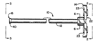
Fig. 1 is an enlarged side view of a packaging
sheath for an intra-aortic balloon catheter, employing
10 t~lrhin~C of this invention.
Fig. 2 is a right-end view of the device of Fig. 1,
taken generally along line 2-2 and looking in the
direction of the arrows.
Fig. 3 is a left-end view of the device of Fig. 1,
5 taken generally along line 3-3 of Fig. 1 and looking in
the direction of the arrows.
Fig. 4 is a somewhat enlarged side view, partially
in section, illustrating the construction at the junction
of the sheath tube and the end portion of the device in
20 Fig. 1.
Fig. 4A is a further enlarged fragmentary sectional
view COL L ~ n-l i n~ to Fig . 4 .
Fig. 5 is an enlarged side view of the catheter
removal end of the device of Fig. 1, taken partially in
25 section along an axial dii LLal plane as indicated by
line 5-5 of Fig. 3.
Fig. 6 is a sectional view taken generally along
line 6-6 of Fig. 1.
Fig. 7 illustrates the positioning of a core pin and
30 injection mold relative to a sheath tube for forming ân
end ell~L~ce and related entry p~ eway configuration
of the device of Fig. 1.
Fig. 8 is a sectional view showing the distal end of
the sheath tube mounted on a heated tipping die for
35 reforming this end of the sheath tu~e.
Fig. 9 is a view COLL~ din~ to Fig. 8, showing
the distal end being ref ormed by inversion .
_ __ . . _ .. _. . . . ___ __
woss/2s466 r~ A7l~
2185814 6
While the invention will be further described in
connection with certain pref erred : ': ; r ~ Ls ~ it is not
intended to limit the invention to those Pmho~ -ts. On
the ~ .LLC~Ly, it is intended to cover all alternatives,
5 modif ications and equivalents as may be ; nrl~ Pd within
the spirit and scope of the invention.
n~TATTT~n DESCRIPTION OF ~ K~ EMBODIMENTS
A packaging sheath unit 10 is illustrated which
10 comprises an elongated sheath tube 12 with a T-shaped
entrance end section 14 at one end. The opposite end
portion of the tube, at its distal or exit end 16 is
reformed by being inverted outwardly and back upon
itself, as will be referred to further below.
The tube 12 is a small circular cylindrical tube,
typically being cut from an indeterminate length of
L uded plastic tubing . The entrance section 14
includes a center portion 22 which is in co-axial
~iuLL~,u-lding relationship to the respective end portion of
the tube 12 and the axial extension of its inner
cylindrical bore, and a pair of oppositely ~ posPd wing
portions 23. The wing portions extend outward from the
center portion 22, forming a T-shape therewith.
The section 22 includes a collar portion 24, a guide
portion 28 and an intervening portion 34. The collar
portion 24 ~ULL~UIIdS and is bonded to the adjacent end
portion 26 of the tube. The guide portion 28 defines a
truncated conical or funnel shaped smooth interior guide
surface 30 which is spaced from and rOA~Ally aligned
with the distal end 32 of the tube 12. The intervening
portion 34 defines a circular cylindrical surface 36
which is co-axial and congruent with the inner bore
surface 38 of the end portion 26 of the tube 12 and
extends outward to an intersection with the surface 30.
The surfaces 30, 36, 38 form a smooth continuous series
of surfaces comprising the funnel shaped entrance, the
intervening portion and the inner bore of the tube,
W0 9~5466
2185814 7
without any sharp edges, sho~ Prs, cut-edges, burrs or
rouqhn~. This provides a smooth continuum of ~urfaces
from the t:llLLCli~c~ end of the guide 30 into the tube 12
for insertion of the balloon section of the catheter into
5 the sheath unit 10 with little or no risk of abrasion,
-j scratching or tearing of the material of the balloon,
even where the furled balloon has a snug compacting fit
in the bore 38.
The end section 14 also provides a convenient
10 gripping area or handle for ~nir~ ting and securing the
sheath unit during insertion of the catheter assembly
into the tube 12, and subsequently withdrawing the
catheter unit therefrom. The end section 14 also is
useful for securing and retaining the sheath unit in an
15 appropriate cavity of a shipping tray both during
shipping and while the catheter assembly is withdrawn
therefrom, in the r~ d mode of removal of the
catheter units at the point of use. Thus, while the
illustrated configuration of the external portions is a
20 T-shape c~LL-~-L,. ~linq generally to catheter sheaths used
heretofore by the Cardiac Assist Division of St. Jude
Medical , Inc ., it will be appreciated that any of a
variety of conf igurations may be employed .
Referring particularly to Fig. 5, at the distal end
25 16 a short end portion 40 of the tube wall is inverted
over the adjacent portion 42 to lie circumjacent thereto,
forming an intervening annular fold or bight 44 and
thereby readily forming a smoothly rounded annular exit
surface 46 from the bore of the tube 12. The resulting
30 exit surface avoids exposure of the balloon to any cut
edges, other sharp corners or rollqhn~c as a balloon
catheter section is withdrawn through this end of the
sheath, even if the withdrawal is not directly co-axial
but is at some angle of def lection in any direction
35 relative to the extended axis of the tube 12.
A preferred manner of forming the entrance section
14 by injection molding is illustrated schematically in
.. .. ... . _ _ _
Wo 95l25466 r~
21~5~14 a
Fig. 7. The respective end portion 26 of the tube 12
extends into an a~L-~Liate cavity of an injection mold
50. A core pin 52 includes a cylindrical smooth surfaced
extension 54 which preferably is slightly oversize
5 relative to bore 38 to provide a slight interference fit
within the bore of the tube 12. The core pin 52 also
includes a smooth-walled truncated conical section 56 for
forming the entrance guide surface 30. It will be
observed that the tube 12 is positioned such that its
10 proximal end 32 is spaced a significant distance from the
conical surface 56, for the formation of the transition
section 34 and related smooth inner surface 36
therebetween. An appropriate molding material is
injected into the cavity in a known manner to form the
15 end section 14.
The material to be molded for forming the section 14
should be compatible with the material of the tube 12,
such as to ef f ect a good bond therebetween . In the
preferred ~mhorli-- L both the tube and the injection
20 molding material are high density polyethylene to insure
compatibility and substantially the same melting
t~ ClLUL~:S~ e.g. 380-450F range, or about 420F. It
is believed that the use of c~ l; n~ materials
results in partial melting of the mating annular and end
25 surfaces of the tube 12 in the course of the injection
molding of the end section, thereby providing a
melt/merge fusion bond at these interfaces and
particularly at and along the interface of end 32, which
further assures the formation of a unified continuum of
3 o surf aces from the tapered guide surf ace 3 0 into the bore
of the tube 12. Accordingly, the drawings sometimes show
the interfaces between the sheath tube and the molded-on
end section in da~hed lines.
By way of further example, for packaging an 8 Fr
35 IABC the tubing 12 is an extruded high density
polyethylene tube having an ID of about .120", an OD of
about .133" and a wall thickness of about .065". The
_ _ _ _ _ _ _ _ _ _ _ _ _ _ _ _ _ .. _ _ _ _ . _ _ _ .. ... _
W0 95/25466 1~
~85814 9
collar Eection is about .250" in length overall, which
includes a transition surface section 36 about . 025"
long, and a conical entrance 30 with an inr ll7~r9 angle of
about 60. The main body of each wing is about .310"
5 wide and .098" thick, and the two wings 23 have a total
span of about 1.19".
The inverted configuration of tle distal end 16 may
be provided by any suitable t~hn i ~1 ~ . A currently
preferred method is a hot die forming process as
10 illustrated generally in Figs. 8 and 9. A die block 70
is f ormed with an appropriate generally u-shaped recess
72 to receive one end of the tube 12. A die pin 74
extends co-axially into the cavity 72 and is of a size to
fit snugly within the bore of the tube 12. The pin 74,
15 and adjacent portions of the block 70 if and as
nec~6F~ry, are heated by any d~Lo~Liate means to a
LuL~ sufficient to soften the material of the
inserted end portion of the tube 12 such that axial
pL~ ULr~ cau&es the distal tube portion 40 to be
20 p~oy~,~ssively inverted over the next adjacent tube
portion 42, as illustrated. That is, the end portion 40
is progressively enlarged in diameter and turned back in
circ~mjacent relation to the next sll~ cee~7.;n~ portion 42
of the tube. The result is a rounded, smooth annular
25 exit surface 46 formed by reverse bending and rolling
back the end portion 40 of the tube 12. Any sharp edges,
burrs or roughness that may have been f orm7ed at the
distal end of the tube 12 during its formation are
removed from the area of contact with the balloon during
3 o withdrawal . The pin 74 and cavity 72 may be of a
configuration to also provide a slight outward taper or
- flare in the exit end of the sheath tube, as illustrated
in Fig. 5.
It will be appreciated that improved packaging
35 sheaths for the balloon portion of intra-aortic balloon
catheters have been provided which meet the objects of
this invention.
.. . ... . ...
WO 95l25466 P~ .,,5lQ~ 1 ''
2l85814 LO O
The invention has been described in con61derable
detail with reference to certain e~mho~; L6, and
particularly with respect to the preferred ~mhor~ 5
thereof. However, it will be under6tood that variation6,
5 modifications and; ~ 6 may be made, particularly
by tho6e 6killed in thi6 art and in light of the
tea~h i n~6 ref erred to herein within the spirit and 6cope
of the invention a6 claimed.