Note: Descriptions are shown in the official language in which they were submitted.
~1~S~7S
ELECTROCHEMICAL SENSOR
1. Field of the Invention
This invention relates to instruments for sensing the
characteristics of a fluid, more particularly to
electrochemical sensors and particularly, but not
exclusively, to reference cells used in pH, ORP, or other
specific ion sensors.
2. DescriPtion of the Prior Art
The reference cell used in pH, ORP, or other specific
ion sensors typically utilizes a metal-metal salt (e.g.,
Ag/AgCl) element. In order for this reference element to
maintain a common electrical potential with the specimen
fluid, a suitable electrolyte in the form of a salt solution
must link this element to the specimen fluid. This
electrolyte provides the conductive, i.e., salt, bridge to
the specimen fluid and surrounds the reference element with
an electrochemically stable environment. The region where
the electrolyte meets the specimen fluid is called the
liquid junction and usually takes the form of a porous
material.
The ideal liquid junction would provide electrolytic
contact between the reference element and specimen fluid
while preventing any mixing of the specimen fluid with this
electrolyte. In practice, mixing is usually unavoidable and
can cause undesirable effects. Thus, the liquid junction
is typically the weakest point of a reference cell design.
Current liquid junction designs employ various porous
material such as wood, Teflon , ceramic frits, wicks,
ground glass joints, or even just a small hole. These
junctions either separate the specimen fluid from a
reservoir of electrolyte containing the reference element
or are saturated with the electrolyte fluid and house the
reference element in a location far removed from the
specimen fluid.
A common problem with liquid junctions is maintaining
a conductive path between the specimen fluid and the
reference element. Liquid junctions with small openings can
easily be plugged by solids contained within the specimen
2185~79
fluid or by crystallization of the specimen fluid with the
electrolyte through some type of chemical reaction. To
reduce plugging problems, large junction surfaces have been
employed.
In U.S. Patent No. 3,440,525 ("the '525 Patent") to
Cardeiro, he discloses a liquid junction that employs a
large junction surface created by a single wood or porous
ceramic plug. The structures of these materials maintain
electrolyte contact through small capillaries extending
longitudinally between the specimen fluid and reference
electrolyte. The liquid junction of the '525 Patent
possesses a very high density of electrically conductive
salt links to the specimen fluid via the capillary structure
of the wood or ceramic plug.
Another common difficulty with reference cell designs
is isolating the reference element from the specimen fluid.
As the specimen fluid penetrates into the liquid junction
and electrolyte reservoir, the electrolyte concentration
decreases and will eventually cause the potential produced
by the reference cell to drift. With time, the potential
will reach levels too large for calibration methods. If the
specimen fluid reaches the reference element, poisoning of
this element can occur, causing the reference potential to
become unstable. Since these are undesirable effects, the
design of the reference cell should minimize or eliminate
the exchange of electrolyte with specimen fluid.
In U.S. Patent No. Re. 31,333 ("the '333 Patent") to
Barben, he discloses the use of multiple plugs of
semipermeable material, such as wood, with longitudinal
capillaries extending from one end of the plug to the other.
These plugs are linked through a series of smaller plugs.
The '333 Patent teaches that an epoxy resin or other
adhesive sealant should be used to seal the abutting end
surfaces of the large plugs prior to assembly of the
reference cell described therein. According to the '333
Patent this use of the sealant causes the ion transfer path
- ~8~S7g
to be longitudinally and transversely linked between each
plug.
Each of the large plugs has a pair of side apertures
which are axially displaced on opposite sides of the plug's
central bore. The side apertures are used to receive the
smaller plugs which are inserted midway into one of the side
apertures in successive pairs of the large plugs on opposite
sides of the central bore. The '333 Patent teaches that the
sealant fills the intervening spaces within the side
apertures to seal off the fluid path between successive
smaller plugs on each side. Therefore, the '333 Patent
teaches that the combination of large and small plugs and
sealant provides a circuitous path for ion transfer.
According to the '333 Patent, after the large and small
plugs are assembled, placed in a cylindrical container along
with a central glass electrode and the sealant has cured,
the entire structure is immersed in a bath containing the
reference cell electrolyte or salt bridge solution until the
wood is thoroughly impregnated with this solution throughout
the entire length of the container. The '333 Patent teaches
that the absorption of the salt bridge solution into the
reference cell structure causes swelling of the large and
small wood plugs. This swelling causes the wood to expand
in the transverse direction which causes the plugs to
tightly press against one another, the central glass
electrode and the inside of the rigid cylindrical container
used to house the cell. While not expressly stated in the
'333 Patent, this swelling of the wood would lead one
skilled in the art to presume that there would be very
little if any ion transfer in that part of each plug
adjacent to the glass electrode and cylindrical container.
In practicing the invention taught in the '333 Patent,
epoxy has also been used to seal the outside surface of each
of the large plugs. It was believed that using the epoxy
on the outside surface would further ensure that there would
218~79
not be any ion transfer along a path through the outside
surface of each plug.
Reference cells constructed in accordance with the
teachings of the '333 Patent have been and continue to be
used successfully in the continuous monitoring of process
streams. One such application is in the monitoring of
process streams wherein sulfides are present. Such streams
may occur in petrochemical processes, flue gas scrubbers,
and waste water treatment. The presence of sulfides in
these streams has been shown to shorten the life of a
reference cell. As sulfides penetrate into the reference
cell structure and come in contact with the metal ions
involved in the reference cell reaction (e.g., silver), an
insoluble sulfide salt forms and precipitates out of
solution. Since maintaining a constant reference cell
potential relies on the equilibrium established between the
metal and metal ions in the reference cell (i.e., the
reference cell reaction), the irreversible reaction with
sulfide ions depletes all of the available metal ions.
Without any appreciable metal ions, the reference cell will
not be well behaved and will render the sensor useless.
Reference 'poisons' like sulfides can only be controlled by
preventing or restricting these ions from making direct
contact with the reference element.
While a reference cell constructed in accordance with
the teachings of the '333 Patent has been found to have a
longer life than other known reference cells, sealing
weaknesses with the region between the glass electrode,
cylindrical container, and adjoining surface of the large
wood plugs have been observed using a dye solution.
Poor sealing against the glass electrode relates to the
manufacturability of the device. Since the swelling of the
wood plugs within the reference cell is highly
unpredictable, ensuring a reliable and reproducible seal
between the glass electrode and wood plugs is quite
difficult. If inadequate spacing is used between these
2185~79
components, the final product yields either a sensor with
a broken glass electrode and an unusable device or a sensor
with inadequate sealing and shortened sensor life. The same
situation occurs with the sealing area between the wood
plugs and cylindrical container.
Finally, the seals between each large wood plug are
compromised during the impregnation process. Due to the
rougher surface typical of end cuts across the wood grain,
any delamination between the sealant (i.e., epoxy) and large
wood plugs creates open channels.
Though these weaknesses have not greatly impacted
sensor life in most applications, a reference cell that has
an increased life when used in the monitoring of process
streams where sulfides are present is desirable.
Additionally, most measurement cells (i.e.,
electrodes) have a tubular, glass construction. The
compressive loading resulting from the swelling of the large
wood plugs would in theory be evenly distributed over the
circular structure of the tubular glass electrode. Since
most glass materials possess very good compressive strength
it would then be expected that the electrode could handle
such compressive loading. Unfortunately, the swelling is
not uniform from plug to plug or from side to side on a sole
plug. Thus, the loads placed on the glass electrode
typically are in the form of both compressive and shear.
Such loading may cause breakage of the glass electrode
when a sensor that uses porous material in its liquid
junction design is placed into service in process streams
having elevated temperatures, pressures and/or containing
harsh chemicals. Examples of such sensors are those shown
in the '333 Patent and also in U.S. Patent No. 5,147,524
("the '524 Patent") and U.S. Patent No. 5,346,606 ("the '606
Patent"). The heat, pressure and/or chemicals may cause the
porous material to expand and fracture the glass electrode.
Therefore, it is desirable to strengthen the sensor to
thereby eliminate this cause of glass electrode fracture and
2185~79
thus allow a sensing device to be provided having a
consistent quality and performance.
Summary of the Invention
The present invention is embodied in a device for use
in connection with measuring ionic properties in a specimen
fluid. The device has a salt bridge which is made up of a
first longitudinal series of semipermeable plugs impregnated
with an electrolyte; and a second longitudinal series of
semipermeable plugs impregnated with an electrolyte. The
first and said second series of semipermeable plugs are
disposed in a longitudinally overlapping relationship with
an interlocking fit.
The device also has a series of impermeable plugs.
Each of the impermeable plugs are associated with a pair of
adjoining transverse end surfaces of the first series of
plugs and are interposed therebetween. A plug in the second
series of plugs passes through each of the impermeable plugs
to thereby provide an ion path between the adjoining
transverse end surfaces.
The present invention is also embodied as a device for
use in connection with measuring ionic properties in a
specimen fluid that has a salt bridge wherein the first
longitudinal series of semipermeable plugs has at least two
plugs and the second longitudinal series of semipermeable
plugs has at least one plug. The first and second series
of plugs are disposed in a longitudinally overlapping
relationship with an interlocking fit. The device also
includes a series of impermeable plugs having at least one
plug associated with adjoining transverse end surfaces of
the at least two plugs in the first series and is interposed
therebetween. The at least one plug in the second series
passes through the at least one impermeable plug to thereby
provide an ion path between the adjoining transverse end
surfaces.
The present invention is further embodied as a device
for use in connection with measuring ionic properties in a
21~879
specimen fluid that has a salt bridge. The salt bridge has
first and second longitudinal semipermeable plugs
impregnated with an electrolyte; and a third longitudinal
semipermeable plug impregnated with an electrolyte. The
first, second and third plugs are disposed in a
longitudinally overlapping relationship with an interlocking
fit. The device further has an impermeable plug interposed
between adjoining transverse end surfaces of the first and
second semipermeable plugs. The third semipermeable plug
passes through the impermeable plug to thereby provide an
ion path between the adjoining transverse end surfaces.
The present invention is also embodied as an
electrochemical sensor. The sensor has a reference
electrode; a sensing electrode; a rigid liner; and a salt
bridge. The salt bridge has a plug made of semipermeable
material saturated with an electrolyte. The plug has a
central axial bore for holding the rigid liner therein. The
rigid liner has a central axial bore for holding the sensing
electrode therein.
The present invention is also further embodied as an
electrochemical sensor. The sensor has a semipermeable plug
impregnated with an electrolyte. The plug has a central
bore and axially separated first and second ends and
functions as a salt bridge. The sensor further has a rigid
liner in the axial bore; a sensing electrode positioned at
the first end and adapted to contact a specimen fluid; and
a reference electrode positioned at the second end.
Description of the Drawing
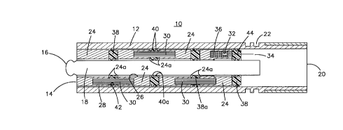
Fig. 1 shows a cross sectional view of a sensor
embodied in accordance with one aspect of the present
invention.
Fig. 2a shows a cross sectional view of a sensor
constructed in accordance with the teachings of the '333
Patent at the end of the ink test.
Fig. 2b shows a cross sectional view of the sensor
shown in Fig. 1 at the end of the ink test.
2~879
Fig. 3 shows a cross sectional view of the sensor of
Fig. 1 including a rigid liner in accordance with another
aspect of the present invention.
Description of the Preferred Embodiment(s)
Referring now to Fig. 1, there is shown a cross
sectional view of a sensor 10 embodied in accordance with
the life expectancy increasing features of the present
invention. For ease of description, the embodiment of the
sensor shown in Fig. 1 will be referred to hereinafter as
a "sensor." The sensor may be used for measuring pH, ORP
or specific ions in a specimen fluid (not shown).
As shown, the sensor 10 includes a housing 12 which is
preferably cylindrically shaped. Typically, housing 12 is
formed with high density polyvinyldiene fluoride plastic or
other material that has the desired structural rigidity and
is inert or otherwise chemically compatible with the
specimen fluid. The housing 12 has a first end 14, and the
bulb 16 of a conventional glass sensing electrode 18
protrudes from the first end 14 to contact the specimen
fluid for measuring, for example, the pH of the specimen
fluid.
Fig. 1 also shows that the housing 12 has a second end
20, and that a coupling sleeve (not shown) and the O-ring
glands 22, can be used to seal the second end 20 from the
specimen sample, and that this coupling sleeve provides for
the necessary engagement with a complementary fitting (not
shown) on a pipe, tank, or other vessel that holds the
specimen fluid. As is well known, electrical leads (not
shown) are attached to the glass sensing electrode 18 and
reference electrode 32 and extend outwardly from the second
end 20. The electrical leads are for attachment to a
suitable device, for example, a pH meter, which can process
the signal generated by the sensor lo and indicate the pH
of the specimen fluid. As is also well known, the second
end 20 is fill with a potting material (not shown) suitable
for the type of environments typical for this device. The
2185~79
potting establishes a seal between the electrical leads,
rear of button 38 and housing 12.
As is also shown in Fig. 1, two overlapping series of
interlocking plugs fill the interior of the housing 12
surrounding the glass electrode 18. In the specific
embodiment illustrated, the first series consists of four
thick walled hollow cylindrical or annular shaped larger
plugs 24 that fit snugly within the housing 12. Each of the
plugs 24 have a central bore 26 that slidably receives the
axially disposed glass electrode 18 at the center of the
housing. Each of the adjoining surfaces 24a of plugs 24
also has a single longitudinally extending side aperture 28
axially displaced on one side of the central bore 26. The
aperture 28 only extends about halfway through each plug.
The second series of plugs are the three solid
cylinders 30 that are slidably insertable into the side
apertures 28 of adjacent pairs of the plugs 24. The plugs
30 have approximately the same longitudinal dimensions as
the plugs 24 for insertion midway into the side apertures
28 thus overlapping the longitudinal extent of adjacent
pairs of plugs 24. only one plug 30 is used between each
adjacent pair of plugs 24 with successive ones on alternate
sides of the central bore 26.
The sensor includes a reference electrode or element
32 that has an electrical lead 34 which accompanies the
electrical lead of the sensing glass electrode 18. The plug
24 closest to second end 20 may include a cavity 36 for
receiving the reference element 32. The reference electrode
32 is typically a conventional silver-silver chloride or
calomel type electrode. The plugs 24 and 30 are saturated,
that is, impregnated, with an appropriate electrolyte such
as a saturated salt solution. This saturation allows
electrical communication to be established through the plugs
24 and 30 between the reference electrode 32 and the
specimen fluid in which the bulb 16 of the measurement
electrode 18 is immersed.
21~79
A comparison of the '333 Patent with the description
above of the sensor of the present invention would show that
the description above also essentially describes the sensor
shown in the '333 Patent. There are differences between the
sensor described in the '333 Patent and the sensor of the
present invention. For example, in the sensor described in
the '333 Patent each of the larger plugs has a pair of
longitudinally extending side apertures completely
therethrough while the sensor described herein has the
longitudinally extending apertures 28 only partway through
the plug 24. The '333 Patent describes and shows a set of
cylindrical plugs which are about twice as long as the plugs
30 described herein.
There are additional and more significant differences
between the sensor described in the '333 Patent and the
sensor of the present invention. As was previously
described herein, the '333 Patent teaches that an epoxy
resin or other adhesive sealant should be used to seal the
abutting end surfaces of the plugs 24 prior to assembly of
the sensor. As was further previously described herein, the
'333 Patent teaches that the sealant fills the intervening
spaces within the side apertures 28 to seal off the fluid
path between successive smaller plugs 30 on each side of the
larger plugs 24. As was also previously described herein,
in practicing the invention taught in the '333 Patent, epoxy
has also been used to seal the outside surface of each of
the large plugs 24.
Referring once again to Fig. 1, it can be seen that in
the sensor of the present invention adjacent end surfaces
of the plugs 24 are separated from each other by a "button"
38 fabricated from an impermeable material. The second end
20 of the sensor is sealed by a button 38. Each button 38
includes a pair of semicircular protrusions 40 by which an
0-ring type seal is provided against the housing 12. All
of the buttons 38 have a central bore 38a for slidably
receiving the glass electrode 18. This central bore has a
2185~79
-
pair of semicircular protrusions 40a similar to protrusions
40 to thereby provide an O-ring type seal with the glass
electrode 18.
The three buttons 38 which separate the adjacent end
surfaces of -the plugs 24 each further include a single
longitudinally extending side channel 42 completely
therethrough for receiving the associated plug 30. The side
channel 42 provides limited clearance of the associated plug
so that the squeeze created from the semicircular
protrusions 40 and 40a causes channel 42 to tightly squeeze
against the associated plug 30. The button 38 which seals
the second end 20 does not include channel 42 but does
include a single longitudinally extending side channel 44
completely therethrough for receiving the electrical lead
34 of the reference electrode 32. In one embodiment of the
present invention, the impermeable material used to
fabricate the buttons 38 is VITON~ rubber which is available
from E. I. Du Pont De Neumors & Co.
In order to determine if a sensor embodied as shown in
Fig. 1 would have a longer life than a sensor constructed
in accordance with the teaching of the '333 Patent, the two
sensors were tested at the same time and identically. Using
an apparatus that cyclically applies air pressure to the
center opening of a piping tee filled with an ink solution,
sensor life can be inferred by comparing the penetration of
the ink solution into each sensor over a period of a few
days. At the end of each test, both sensors including
wooden plugs were longitudinally cut open.
Referring now to Figs. 2a and 2b, there is shown in
Fig. 2a a cross sectional view of a sensor 50 constructed
in accordance with the teachings of the '333 Patent at the
end of the ink test and in Fig. 2b a cross sectional view
of the sensor 10 shown in Fig. 1 also at the end of the ink
test. The results of the ink test for both sensors is shown
in Figs. 2a and 2b by the dark shading, which represents the
ink stains, on the plugs 24 and 30.
- 2185879
As can be seen in Fig. 2a, the ink stains on the plugs
24 in the sensor 50, and a variation (not shown) of the
sensor 50 wherein an elastomeric sealant was used around the
wood reference structure, showed that the ion transfer path
was either on the inside of each plug 24 adjacent to the
glass electrode 18/elastomeric sealant or on the outside
surface of each plug 24 adjacent to the housing
12/elastomeric sealant. Ink stains were absent in the
central portion 52 of the reference cell for sensor 50.
Additionally, a great deal of staining was apparent in the
regions between the epoxy and the adjoining surfaces 24a of
the large wood plugs 24. Apparently the swelling of the
plugs during impregnation by the salt solution caused the
epoxy on the outside surfaces to crack and/or delaminate.
As can be seen in Fig. 2b, the ink stains in sensor 10
showed a uniformed progression leading from the specimen
fluid contact point through each of the large and small
plugs 24 and 30. Staining showed complete saturation of
each large plug 24 before any appreciable staining was
observed in the next adjacent large plug 24. Thus, the ink
stains in the sensor 10 of the present invention and the
sensor 50 of the '333 Patent prove that if the '333 Patent
sensor or its modified form (i.e., with elastomeric sealant)
had been used in a sulfide application its reference cell
would have been poisoned much sooner than the reference cell
of the sensor 10.
As previously described herein, inadequate clearances
between the cylindrical housing 12 and glass electrode 18
of the sensor 10 or the sensor 50 or even sensors embodied
in accordance with the teachings of the '524, 525 and '606
Patents can give rise to either a sensor with a broken glass
electrode or a sensor with inadequate sealing and shortened
life. Referring now to Fig. 3, there is shown a cross
sectional view of a further embodiment of sensor 10 which
includes a rigid tubular liner 60 around the glass electrode
18. As is shown in Fig. 3, the wall 64 of the rigid liner
i~85~79
60 is thicker in portion 62 adjacent to first end 14 then
elsewhere. The increased wall thickness in portion 62
allows for the use of standard size O-rings 66 which
provides a seal to prevent the specimen fluid from reaching
the potted electrical leads and aid in retaining the glass
electrode 18.
Each of the large plugs 24 must be reduced slightly in
diameter as compared to their diameter in the sensor shown
in Fig. 1 in order to accommodate liner 60. In addition and
as is shown in Fig. 3, the portion of the plug 24 which is
closest to end 14 must have a step 25 therein which is
complementary to portion 62. The rigid liner 60 has a
groove 68 which is used to accommodate a snap ring 70. The
snap ring 70 retains the assembly made up of plugs 24, 30,
buttons 38, liner 60 and 0-rings 66. This allows the glass
electrode 18 to be inserted into that assembly just prior
to shipment of the sensor 10.
It should be appreciated that the use of rigid liner
around glass electrode 18 minimizes the clearances
between the large wood plugs 24, cylindrical housing 12, and
cylindrical liner 60 without any concern that the glass
electrode will be fractured after impregnation of the
sensor. The smaller clearances will greatly enhance sealing
between the cylindrical housing and the rigid liner and also
give rise to a consistent quality and performance of the
sensor 10.
In one embodiment for the sensor shown in Fig. 3, the
rigid liner 60 was constructed from either stainless steel
or titanium. The rigid liner may, however, be constructed
from any material that can withstand the shear stresses that
may result when the sensor is impregnated and later placed
into service in process streams having elevated
temperatures, pressures and/or containing harsh chemicals.
An advantage of using an electrically conductive material
for the liner is in those applications which require a
solution ground. In such applications the ground can easily
~1~5879
be provided by connecting a wire (not shown) to the snap
ring 70.
Liner 60 has been shown in Fig. 3 in combination with
sensor 10 of Fig. 1. It should, however, be appreciated
that the liner may also be used with sensor 50 of Fig. 2a
or any other type of sensor which uses a porous material in
its liquid junction and has an electrode that may fracture
under shear stresses.
It is to be understood that the description of the
preferred embodiment(s) is (are) intended to be only
illustrative, rather than exhaustive, of the present
invention. Those of ordinary skill will be able to make
certain additions, deletions, and/or modifications to the
embodiment(s) of the disclosed subject matter without
departing from the spirit of the invention or its scope, as
defined by the appended claims.