Note: Descriptions are shown in the official language in which they were submitted.
X18589
Car body surface treatment device
The invention relates to a surface treatment device for one or
more car bodies, having a rotating device, to which at least
one car body mounted on a loading carriage is detachably
connectable and which dips the car body into a treatment bath
by rotation and in turn takes it out of said bath by a
rotation, as well as having conveyors for carrying the loading
carriage on to or away from said rotating device.
A device for the surface treatment of car bodies, which are
dipped by rotation into a treatment bath and are taken out of
same by counter-rotation, is known from GB 2 229 381. In this
known device, a car body is securely connected to a loading
pallet. This unit composed of a loading pallet and car body
mounted thereon is fitted on to a roller carriage. This roller
carriage is equipped with non-driven rollers which enable a
displacement to the side of the car body's longitudinal axis.
By means of such a non-driven roller carriage, the loading
pallet is conveyed from the treatment bath to other processing
stations.
The entire composite structure, consisting of the car body,
loading pallet and roller carriage, is pushed on to a mount
which is attached above each treatment bath. This mount has a
rotation axis perpendicular to the car body's longitudinal axis
or parallel to the direction of conveyance. By rotation around
the rotation axis through 180°, the entire composite structure
of car body, loading pallet and roller carriage can now be
dipped into the treatment bath. During the immersion operation,
this mount and the unit of car body, loading pallet and roller
carriage are connected together by means of locking pins.
A conveyor belt extending across several treatment stations and
their treatment tanks is used to transport the car bodies or
roller carriages. These treatment stations are laterally
~ 18589
adjacent. The conveyor belt transports the roller carriages, on
which a loading pallet with its car body is respectively
fitted, from treatment tank to treatment tank. Vertically
positioned pallet pieces, which make contact with the roller
carriage, are fitted on the conveyor belt for this purpose.
This type of device for the introduction of a car body enjoys
the advantage that a simple mechanism is used to minimize the
extent to which the treatment fluid in the treatment bath is
spilled, in that the car body is rotated into the treatment
bath via the front or the rear side. During the rotation
process, the quantity of air entrapped within the car body is
continuously able to escape from the car body's windows.
This device's structure is relatively complex and only suitable
for small-scale systems. When a car body is immersed, the next
body must wait until the first body's process time has elapsed.
This process time amounts to as much as three minutes in the
case of individual process stages and is even longer in the
case of cathodic dip painting.
DE 43 04 145 C1 describes a device of the named class in which
a car body is also dipped into a treatment bath by means of
rotation. In the case of the immersed car body, it is also
possible for another car body to be fitted on to this rotating
device and to be detachably connected or for it to be able to
pass over the rotating device.
In the known device, a loading carriage is used to receive and
fix the car body. The loading carriage and car body are pushed
on to the rotating device by means of one or more driven
rollers and are detachably connected thereto by means of fixing
devices. The rotating device is attached above the treatment
bath and comprises a rotation axis transverse to the direction
of conveyance of the car bodies. The car body is now introduced
by rotating the rotating device in such a manner that the car
body is dipped via its front or rear side into the treatment
2
21~~898
bath. One or more of the rollers on the upper and lower sides
of the rotating device are respectively driven so that the
loading carriages and car bodies can be passed along.
This design suffers from the disadvantage that the rotating
device comprises a plurality of mechanically mobile parts
(guidance rollers and rollers for moving the loading carriage)
which accumulate a significant amount of dirt as a result of
the painting process and which contaminate the paint bath with
dried paint residue. Because the rollers are repeatedly dipped
in the treatment bath, their functioning cannot be ensured even
after a short period of time.
The technical problem upon which the invention is based is to
provide a car body surface treatment device in which
accumulation of dirt on the mechanically mobile parts is
largely avoided when the car bodies are introduced by rotation.
This technical problem is solved in a device according to the
class in that the conveyors are located outside the treatment
bath and the conveyors located within the rotating device's
area of rotation can be moved out of and into this area.
The invention is based on the idea of arranging the conveyors
used for introducing and removing the loading carriages with
the~car bodies secured thereto, as well as the drive and
guidance rollers, conveyor belts etc. in such a manner that
they themselves do not dip into the treatment tank during car
body treatment, i.e. they are secured separately from the
loading carriage and rotating device. As a result, substantial
dirt accumulation and any malfunctions affecting the drive and
guidance rollers as well as any necessary conveyor belts can be
largely prevented. As a result of the mobile design of the
conveyors, which are located in the area of rotation of the
rotating device with the car body fitted thereon, these parts
can also be guided out of, and if necessary back into, the area
of rotation. A rotary movement of the rotational device can
3
218~8~8
therefore take place in an unlimited manner in its angle of
rotation. The retractable and protractable conveyors also make
it possible to pivot the car body fitted on the rotational
device in its immersed state, thereby allowing the entrapped
air bubbles to escape more effectively, which leads to a
higher-quality coating result.
By guiding the movable conveyors out of the rotating device's
area of rotation during the rotational raising movement, an
accumulation of dirt on the transport or conveying means caused
by paint flowing down the car body is minimized and hence the
risk of dirt accumulating inside the treatment bath due to
residual paint dried on the conveyors is reduced.
The design input is likewise substantially simplified when
designing the rotating device, resulting in lower production
costs and making it less expensive to control and maintain the
system.
In particular, the simple structure of the device according to
the invention makes it possible to increase the cycle rate at
which the car bodies are introduced into the treatment bath by
the fact that it is already possible to start conveying another
car body over the treatment bath even though the preceding car
body has not yet been completely immersed, thereby increasing
the~capacity of the entire system (several baths connected in
series). All in all, the immersion process is improved by these
measures in terms of achievable coating quality and economy.
The conveyors advantageously comprise guidance and driven drive
rollers in order to carry the loading carriage and the car body
mounted thereon on to or away from the rotating device. As a
result of this simple structure, a loading carriage is guided
between a number of facing rollers, whereby one or more of
these rollers are driven, causing the loading carriage to be
moved by transfer of friction. This also makes it possible for
218~~9
a loading carriage to be passed on from one treatment station
to the next in a simple manner.
Since the conveyors located within the rotating device's area
of rotation can be guided out of or into the area of rotation
as required, it is possible to pivot an immersed car body in an
unlimited way. As already mentioned, residual paint and dye,
which contaminate the bath, are also largely avoided in that
the conveyors can be moved away from the dripping area when the
car body which has already been treated is raised.
A very simple and inexpensive design solution for guiding the
conveyor in and out is to attach this conveyor to a sliding
means, such as a hydraulic ram, electrical drive or chain
drive, in a slidable manner across the treatment bath on facing
sides, allowing the loading carriage to be guided or passed on
with its edge regions on the guidance and drive rollers. It is
just as suitable to rotate the conveyors away, in which case
hydraulic, pneumatic or electrical drives are possible.
In order that the rotating device and the loading carriage
detachably connected thereon can be easily rotated, it is
particularly advantageous for the conveyors' individual
guidance and drive rollers to be each fitted with a raised edge
at least on one roller side, causing the loading carriages to
be guided and driven, though the loading carriage guided
thereon is still able to "rotate away in an upwards direction"
without hindrance.
So that the air bubbles entrapped within the immersed car body
can completely escape at the car body's rear or front side, it
is particularly advantageous for the bodies to be immersible
into the treatment bath by rotation through up to 210°, with
the conveyors located in the area of rotation being retractable
or protractable, if necessary.
__
. 218$98
If for example, the configuration of the individual treatment
baths makes it desirable to dip the car bodies into the
treatment bath or to guide them out of it by rotation through
360°, it is particularly advantageous to arrange in a movable
manner all those conveyors located within the area of rotation.
In the device according to the invention, it is advantageously
possible for the car bodies, in their immersed state, to be
able to be rotated through up to 30° in both directions of
rotation so as to enable the entrapped air bubbles to escape
more effectively.
The conveyors with their guidance and drive rollers are
advantageously movably arranged outside the rotating device so
that during the immersion operation, they can be guided into a
position which enables one or more successive car bodies to
pass over the tank or treatment bath, making it possible to
increase further the cycle rate at which the car bodies are to
be treated, with the treatment baths arranged in succession.
If the rotating device is fitted with fixing and locking means
for detachably securing a loading carriage not only on the
upper side but also on the lower side, it is possible, when a
car body is immersed, to fit another car body on the same
rotating device by means of the conveyors attached to the edge
of the treatment bath. Only those conveyors attached above the
treatment bath are advantageously required in the rotating
device according to the invention in order to treat the surface
of several car bodies simultaneously, rather than treating the
surface on the upper and lower sides respectively, as is the
case with the known devices.
The necessary combination of spraying and dipping processes is
made possible by the device according to the invention in which
the known loading carriage technique is used; this applies both
to the pretreatment of the car bodies and to the dip-painting
thereof.
218898
To portray and explain the invention more effectively, an
exemplary embodiment will be described and explained in further
detail with reference to the enclosed drawings as follows.
Fig. 1 shows a schematic longitudinal section of a treatment
tank with a car body surface treatment device
according to the invention, having a rotating device,
Fig. 2 shows a schematic cross section of the device
according to the invention as shown in Fig. 1, and
Fig. 3 shows a horizontal projection of the device according
to the invention, with a rotating device and
conveyors which can to an extent be positioned; the
car body is not depicted in this top view.
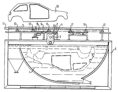
As shown in Fig. 1, in the device according to the invention, a
rotating device 2 is attached above a treatment tank for
treatment bath 1. Rotating device 2 is supported at the left
and right of the ends of a rotation axis 3 by bearing brackets
4 on a container wall 5. Conveyors, which are formed as
guidance rollers 12, drive rollers 13 and slidable guidance and
drive rollers 17 and 18, are located above treatment tank 1.
Drive rollers 13 are driven by an electric motor 15 by means of
a conveyor belt 14. In the state shown in Fig. 1, a loading
carriage 11 with a car body 16 secured thereon is carried on to
rotating device 2 by means of non-driven guidance rollers 12
and driven drive rollers 13. Other guidance rollers 12 at the
side above treatment bath 1 and slidable guidance and drive
rollers 17, 18 are attached in the direction of conveyance
ahead of car body 16 and loading carriage 11.
As schematically shown in Fig. 2, rotating device 2 is fitted
with a frame 8, fixing devices 9 attached thereon and locking
devices 10. Bearing brackets 4, with which the ends of rotation
axis 3 engage, also render apparent the way in which rotating
2~8~~g8
device 2 is supported. Rotation axis 3 - as already mentioned -
is driven via a gear 7 by a drive 6.
Loading carriage 11, shown here without car body 16, engages
with fork-shaped fixing device 9 by means of its longitudinal
members and is guided as a result. Fixing devices 9 are used
for laterally guiding loading carriages 11 while they are being
carried on to rotating device 2. Locking devices 10 comprise a
slidable pin which respectively engages with a recess provided
for this purpose at the side within loading carriage 11.
Locking device 10 may, however, also be fork-shaped in design,
allowing the fork to engage with a corresponding recess when
loading carriage 11 is interlocked.
In the horizontal projection represented in Fig. 3, the regular
distribution of guidance rollers 12 and drive rollers 13 as
well as of slidable guidance rollers and drive rollers 17 and
18 becomes particularly clear. The distances of these rollers
12, 13, 17 and 18 are obtained by the schematically shown
length of loading carriage 11, causing this carriage to be
driven and guided at all times during transportation. In this
exemplary embodiment, only guidance and drive rollers 17 and
18, which are located ahead of non-immersed rotating device 2
and within its area of rotation, i.e. around rotation axis 3,
are designed to be slidable. It is, however, conceivable for
rear rollers 12 and 13 to be slidably designed as well if
rotating device 2 is rotated through 360°.
The operational mode of this embodiment of the device according
to the invention will now be explained.
Before the surface treatment or the treatment of car bodies
commences as a composite structure of several treatment
stations, car body 16 is securely connected to a loading
carriage 11. Loading carriage 11 is transported on to rotating
device 12 via guidance rollers 12 and by means of drive rollers
13.~~The loading pallet of loading carriage 11 is guided by the
g
~1~~$9
side guides of fixing device 9, which are attached to frame 8
of rotating device 2.
If loading carriage 11 is correctly positioned on rotating
device 2, geared motor 15 of drive rollers 13 is brought to a
halt and the loading carriage is securely connected to rotating
device 2 by locking devices 10. This takes place by squeezing
locking devices 10 or by fastening them with pins; these
locking devices engage inside loading carriage 11.
Movable guidance rollers 17 and movable drive rollers 18 above
the forward area of treatment tank 1 are then guided out of the
area of rotation of rotating device 2, i.e. slid outwards by
hydraulic rams in order to make it possible for rotating device
1 to rotate car body 16 subsequently by up to 180° or more.
During the rotating operation, rotating device 2 with loading
carriage 11 and car body 6 secured thereon dips into treatment
bath 1. On completion of the rotation operation, car body 16 is
now completely immersed within treatment bath 1. The rotation
has caused the previous upper and lower sides of rotating
device 2 to be changed around.
If the intention is to dip car body 16 into treatment bath 1 in
the reverse direction of rotation, movable conveyors 17 and 18
are located above the rear area of tank 1.
If a rotation through more than 180° is desired, movable
guidance and drive rollers 17 and 18 both above the front and
rear areas of treatment tank 1 can, depending on the required
angle of rotation, be designed in such a manner that they can
be guided out of and into the area of rotation. As a result,
the entire area above treatment tank 1 is left clear for a
rotary movement in any direction and any angle of rotation.
As soon as the'immersion operation or the rotary movement
allows a position in which guidance rollers 17 and drive
rollers 18, which can be guided out of and into the area of
z ~ s5s9
rotation, no longer impede the rotary movement, these rollers
17 and 18 are correspondingly guided back into their initial
position. It is now possible for a subsequent car body 16 on a
loading carriage 11 to pass over treatment tank 1.
If a pivoting of car body 16 in its immersed state is desired,
guidance rollers 17 and drive rollers 18, which can be guided
out of and into the area of rotation, can be guided into and
out of the area of rotation in order to enable car body 16 to
pivot in both directions of rotation.
In a further exemplary embodiment not shown here, not only the
upper but also the lower side of the rotating device is
provided with a fixing device 9 and a locking device 10. When
car body 16 is immersed, it is then possible to fix a further
loading carriage 11 on what is now the upper side. By rotation
through another 180° or by rotating back through 180°, the new
mounted car body is dipped into treatment bath 1 and at the
same time, the treated car body is guided out of this bath.
~~ 0