Note: Descriptions are shown in the official language in which they were submitted.
wo 96,23g97 - 1 2 1 8 5 9 9 2 PCT/us95/l4034
CONTINUOUSLY VARI'~RI F HYDROSTATIC TRANSMISSION
INCLUDING A PULSE WIDTH MODULATION
RATIO CONTROLLER
REFERENCE TO RELATED APPLICATIONS
The invention disclQsed in this arpli~tion has particular, but not
necessAdly limited appli~lion to the continuously variable hydrostatic
transmissions disclosed in copending U.S. Patent Applications, Serial Nos.
5 08/093,192, filed July 13, 1993; 08/333,688, filed November 3, 1994;
08/342,472, filed November 21, 1994; and (35-OR-962), filed concurrently
herewith. The disclosures of these applications are incorporated herein by
, t fere"ce.
FIELD OF THE INVENTION
The pr~sent invention relates to hydraulic machines and, more
particularly, to hydrostatic transmissions capable of transmitting power from
a prime mover to a load at continuously (i"rinilely) variable transmission
ratios.
BACKGROUND OF THE INVENTION
The continuously variable hydrostatic transmissions disclosed in the
cited copending applications include a hydraulic pump unit and a hydraulic
motor unit posilioned in opposed, axially aligned relalion with an
intermediate, wedge-shaped swashplale. The pump unit is connected to an
input shaft driven by a prime mover, while the motor unit is grounded to the
20 slationary machine housing. An output shaft, coaxial with the input shaft anddrivingly coupled to a load, is connected to the swashplale. When the pump
unit is driven by the prime mover, hydraulic fluid is pumped back and forth
betvrec" the pump and motor units through ports in the swashplate. As a
result, three torque components, all acting in the same tl;~eclion, are exerted
25 on the swas~-plate to produce output torque on the output shaft for driving
the load. Two of these torque components are a me~;l,anic-' component
WO 96123997 PCT/US95/14034
21 85992 -2-
exe, led on the swashplate by the rotating pump unit and a hydromechanical
component exerted on the swashplate by the motor unit. The third
component is a pure hydroslalic component resulting from the differential
forces created by the fluid pressures acting on circumferentially opposed end
5 surfaces of the swashplate ports, which are of difrarent surface areas due
to the wedge shape of the swashplate.
To change transmission ratio, the angular orientation of the
swashplate relative to the axis of the output shaft is varied by a ratio
conl,cller. Since the transmission ratio, i.e., ratio of input speed to output
10 speed, is continuously variable between 1:0 and 1:1, the prime mover can
run at a constant speed set essentially at its most emcient operating point.
The availability of a 1:0 (neutral) transmission ratio setting eliminates the
need for a clutch. As is d;s~lQsed in cited application Serial No. 081342,472,
the swashplale can be positioned to angular orienla~ions beyond the 1:0
1~ ratio setting to provide limited inrinilely variable speed drive in a reversedirection, as well as to angular orientations beyond the 1:1 setting to provide
a limited, infinitely variable, overdrive speed range. Siy~ cantly~ reverse
drive is available without need for a reversing gear mechanism.
Unlike conventional, continuously variable hyd~oslalic transmissions,
20 wherein hydraulic fluid flow rate increases proportionately with increasing
transmission ratio such that maximum flow rate occurs at the highest
transmission ratio setting, the flow rate in the transmissions disclosed in the
cited applications reaches a maximum at a midpoint in the ratio range and
then prog. essively decreases to essenlially zero at the 1:1 transmission ratio
25 setting. Thus, losses due to hydraulic fluid flow are red~ced, and the
- .."oying whine of conventional hydroslalic transmissions at high ratios is
avoided. ~y virtue of the multiple torque components exerted on the
swashplale, the decr~asing hydraulic fluid flow in the upper half of the output
speed range, and the capability of accommodating a prime mover input
30 operd~i. ,9 at or near its optimum performance point, the hydraulic machines
of the cited U.S. patent ~pplic~tions have a particularly advantageous
WO 96/23997 2 1 8 5 9 9 ~ PCT/US95/14034
- 3 -
application as a highly efficient, quiet, continuously variable hydrostatic
transmission in vehicular drive trains.
SUMMARY OF THE INVENTION
An objective of the pr~s6"l invention is to provide an improved ratio
5 controller for controlling a hydrostatic transmission to achieve continuously
variable ratios of input versus output speeds.
A further objective of the present invention is to provide an improved
ratio controller for effectively controlling the rate of ratio change of a
continuously variable hydrostatic transmission in response to speed
10 command signals.
An additional objective of the present invention is to provide an
improved ratio CGI~ ller for changing the swashplate angle in continuously
variable hyd~slalic transmissions of the type disclosed in the cited U.S.
patent applications.
To achieve these objectives, the ratio controller of the present
invention, in its applic~lion to a continuously variable hydrostatic
transmission including an input shaft for receiving input torque from a prime
mover, an output shaft for imparting driving torque to a load, a hydraulic
pump unit, a hydraulic motor unit, and a swashplate operatively posilioned
20 between the pump unit and the motor unit, comprises, in com~.nalion, an
~ctu~tor including a cylinder and a piston disposed in the cylinder to define
first and seco, Id chambers, the ~h ~ator operatively coupled to the
swasl,plale; a first fluid valve having a q~ essent valve position connecting
the first chamber to a source of hydraulic fluid pressure and an actuated
25 valve piston venting the first chamber; a second fluid valve having a
quiescent valve position connecting the second chamber to the fluid
pressure source and ~ctu~ted valve position venting the second chamber;
a module, responsive to speed commands, for selectively ~ctll~ting the first
and second solenoid valves to create difrerenlial fluid pressures in the first
30 and second chambers and thereby produce cor,l,.lled relative motion of the
~nD ES Er~E26)
WO96/23997 2 1 8 5 9 ~ 2 4 PCT/US95/14034
cylinder and piston; and means for translating the relative motion of the
cylinder and piston into ratio-changing movement of the swashplate.
Further in accordance with these objectives, the present invention
provides a method for controlling input-to-output speed ratio of a
5 continuously variable hydn~slalic transmission having a swashplate
operatively positioned between a hydraulic pump unit and a hydraulic motor
unit, the method including the steps of linking an actuator to the swashplate,
the actuator including a piston l~ceived in a cylinder to define first and
second chambers; providing a source of pressurized hydraulicfluid; providing
10 a first fluid valve having a quiescent valve position connecting the first
chamber to the source of pressurized hydraulic fluid and an actuated valve
position venting the first chamber; providing a second fluid valve having a
quiescent valve position connecting the second chamber to the pressurized
hydraulic fluid source and an actuated valve position venting the second
15 chamber; setting a transmission ratio by mainlai,)ing the first and second
fluid valves in their ~ escent valve positions to equalize fluid pressures in
the first and second chambers; changing the transmission ratio by shifting
one of the first and second valves to its actuated position, thereby creating
differential fluid pressures in the first and second chambers to produce
20 relative motion of the piston and cylinder; and translating the relative piston
and cylinder motion into transmission ratio-changing movement of the
swasl ,plale.
Ad-Jitional features, advantages, and objectives of the invention will
be set forth in the desu iptiGn which follows and in part will be apparent from
25 the desc,iptio", or may be lea",ed by practice of the invention. The
objectives and advantages of the pr~sent invention will be realized and
attained by the apparatus and method particularly pointed out in the
following written desuiptiGn and the appended claims, as well as in the
acc~"",&r"~ing drawing.
s~mu ES Er~nE~)
2 1 85~92
WO 96123997 PCT/US95/14034
It will be underaloGcl that both the foregoing general des~;,iplion and
the following detailed des~ ,tion are exemplary and explanatory and are
in~endecl to provide further ex~,lanation of the invention as claimed.
- The accompanying drawing is intended to provide a further
5 under~landing of the invention and is incorporated in and constitutes a part
of the specir,~lion, illustrates a prere"ed embodiment of the invention and,
together with the desuiption, serves to explain the principles of the
invention.
BRIEF DESCRIPTION OF THE DRAWINGS
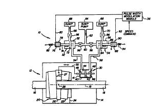
The sole figure of the drawing is a schematic diagram of a ratio
cor,t,lJller according to an embodiment of the present invention in its
application to a continuously variable hydrostatic transmission.
DETAILED DESCRIPTION OF THE PREFERRED EMBODIMENT
The transmission ratio controller in accordance with a preferred
15 embodiment of the present invention, as generally indicated at 10 in the
drawing, is illustrated in its applicaliGn to a continuously variable variation
transmission, generally indicated at 12 and of the type disclQsed in the cited
U.S. patent applications. Thus, as .liag,a",matically illusl,dlecJ in the
drawing, transmission 12 includes a housing 14 in which are jouMaled an
20 input shaft 16 and an output shaft 18 in generally end-to-end, coaxial
relc.lion. Input shaft 16 applies input torque from a prime mover (not shown)
to a hydraulic pump unit, generally indicated at 20, while a hydraulic motor
unit, generally indicated at 22, is grounded to housing 14, as indicated at 24.
Operatively positioned between pump unit 20 and motor unit 22 is a
25 wedge-shaped swashplate 26, which is pivotally connecled to the output
shaft in torque coupled relation as indicated at 28. As described in the cited
U.S. patent applications, swashplate 26 is provided with ports through which
hydraulic fluid is pumped back and forth between the hydraulic pump and
motor units to exert torque components on the swashplate, which are
30 coupled to output shaft 18 as output torque for application to driving wheelsof a vehicle (not shown). As also described in the cited U.S. patent
su~mu ES Er~nE2t)
w0 96/23997 2 1 8 ~ 9 9 ~ - 6 - PCT/US95/14034
arplic~lions, transmission ratio, i.e., input speed on input shaft 16 versus
output speed on output shaR 18, is determined by swashplate angle, that is,
the angular orienlalio~, of swashplate 26 relative to the output shaft axis 19.
Thus, to change transmission ratio, swashplate 26 is pivoted about its pivotal
connection 28 to output shaft 18, as indic~ted by arrow 27, to decrease ratio
(clockwise) or to decrease ratio (counterclockwise).
Ratio controller 10 comprises a hydraulic actuator 30, positioned
within housing 14, a pair of solenoid valves, generally indicated at 32 and
34, for connecting chambers of the actuator to either a common source of
hydraulicfluid underpressure orto atmosphere, and a module 36 connected
to selectively energize the solenoid valves in response to speed command
signals.
Actl~tor 30 is illustrated as comprising a cylinder 40 in which a piston
42 is slidingly received to define a pair of opposed chambers 44 and 46.
Piston 42 is mounted for rec;procaling motion within cylinder 40 by opposed
piston rods 48 extending through hermetically sealed openings in the
cylinder endwalls. The exterior end of one piston rod 48 is linked, as
schematically indicated at 50, to translate reciprocating movement of piston
42 into bidi,e~tional angular movement of swashplate 26 about its pivotal
connection 28 to output shaft 18.
It is to be underslood that the illustrated actuator structure is
exemplary only. It may take a variety of forms, such as, for example, the
various forms illu~l,dted in the cited U.S. patent applications. For example,
as illustrated in cited ~pplic~liol) Serial No. 08/333,668, piston 42 may be
fixedly positiGned, while cylinder 40 undergoes reciprocaling motion and is
thus linked to swashplate 26. Cited application Serial No. 081342,472
illustrales that piston 42 may represent a pair of spherical bearings that
respe~ ely mount pump unit and motor unit cylinder blocks. Coordinated
axial movements of the spherical bearings exert pivoting forces on the
s~4ashplale via the cylinder blocks. Link 50 may take the form of large
dia"~eter cyl~nJ~ical ~etl~tin9 member that reaches around the pump or
2 1 859q2
WO 96/23997 PCT/US95/14034
motor unit to exert pivoting forces on the s~ashplate, as illustrated in cited
~pplicAliol~ Serial No. 08/093,192. Alternatively, the link 50 may include a
cylindrical actuating member that closely surrounds output shaft 18, is
- illustrated in cited application Serial No. 081333,688. Cited application Serial
No. (35-OR-962) illustrates link 50 may represent a hydraulically actuated
piston incGr~,orated in the output shaft.
Retuming to consideration of ~h)~tor 30 in its form illustrated herein,
chamber 44 is connected to a valve chamber 52 of solenoid valve 32 via a
fluid line 54, while chamber 46 is connected to a valve chamber 56 of
solenoid valve 34 by a fluid line 58. Valve chambers 52 and 56 are
connected in common via fluid lines 60 and 62 to a source of hydraulic fluid
pressure, preferable makeup or control pressure available at the output of
a sump pump 64. Valve chamber 52 is also vented, via fluid line 66, to
atmospheric pressure, such as exists in a transmission sump 68. Valve
chamber 56 is likewise vented to sump 68 via fluid line 70.
Solenoid valve 32 also includes a valve member 72 slidingly received
in valve chamber 52. A stem 74 extends from valve member 72 extemally
of valve chamber 52 and is terminated by a solenoid plunger 76. A solenoid
coil 78, wound on plunger 76, is grounded at one end and connected at its
other end by a lead 80 extending to control module 36. Valve member 72
is biased to an illusl,ated ~ escenl position by a spring 82, such that
~c-tl-~tor chamber 44 is normally in fluid communication with sump 60 via
fluid lines 54, 60, and 62.
Solenoid valve 34 is constructed in the same manner as solenoid
26 valve 32, and thus includes a valve member 84 slidingly received in valve
~ a"ll~er 56. A valve stem 86 exlends from valve member 84 to a
terminating solenoid plunger 88, about which a solenoid coil 90 is wound.
The ungrounded end of coil 90 is connected to control module 36 by a lead
92. A spring 94 biases valve member 84 to its illustrated quiescent valve
position, thereby connecting ~c-tl ~ator chamber 46 in fluid commu,)icaliGr, with
the sump pump output via fluid lines 58, 60, and 62.
s~muEsHEr~E2;)
wos6/23ss7 2 1 85q~2 8 - PCT/US95/14034
From the foreyo,ng desc,ipliGn of ratio cor,l.~ller 10, it is seen that,
while solsnGid valves 32 and 34 are in their q!~iescent valve positions,
actuator chambers 44 and 46 are filled with hydraulic fluid at a fluid pressure
equal to the sump pump output pressure. Actuator piston 42 iS thus fixed
in position to set a particular swashplate angle. When a speed command
inputted to control module 36 calls for an increase in transmission ratio,
sole.,oid coil 78 of solenoid valve 32 iS electrically energized to propel valvemember 72 forwardly to a venting valve position illusl,dled in phantom line,
thereby connecting actuator chamber 44 to sump 68 through fluid lines 54
and 66. The fluid pressure in actuator chamber 46, still connected to sump
pump 64 by solenoid valve 34, now exceeds the fluid pressure in actuator
chamber 44. Consequently, piston 42 iS driven leftward to pivot swashplate
26 in the co~"~terclGchwise, ratio-increasing dilection. When the swashplate
has been pivoted to the commanded higher transmission ratio, control
module 36 ce~ses energi ation of solencid coil 78, and solenoid valve 32 is
pulled back to its quiescenl valve position by spring 82, reconnecting
ator chamber 44 to the sump pump 64. Fluid pressures in the ~ctu~tor
chambers equalize to fix the ~ctu~tor piston position and set the swashplate
position to the new, higher ratio setting.
When a speed input command calls for a reduction in transmission
ratio, control module 36 energizes solenoid coil 90 to drive valve member 84
forwardly to its phantom line valve position, thereby venting actuator
chamber 46 to sump 68. The fluid pressure in chamber 44 now exceeds the
fluid pressure in ~c-tl~tor chamber 46, and ~ctu~tor piston 42 iS driven
rightward as the volume of chamber 44 expands, while the volume of
cha"~l~er 46 CGlll(ac~s. Swashplate 26 iS pivoted in the clochwise di,ec~ion
to reduce transmission ratio. When the transmission ratio achieves a setting
satisfying the re~ced speed command, ene,yi~liGn of solenoid valve 34
ceases, and spring 94 retld~a valve member 84 to its solid line position
~econnectilly ~ctu~tor chamber 46 to the sump pump output. Actuator
l;I,a",ber 46 iS then pressurized to the same fluid pressure as ~ch~tor
SU8S111UlES~tl ~RIIIE21;)
wo 96/23997 2 1 8 5 9 9 2 PCT/US95114034
chamber 44, and the new position of ~ctuator piston 42 is sustained to set
the swashplate angle to the commanded, lower transmission ratio.
As illustrated, orifice resl,i~lions 96 may be jOCGI ~,Gr~led in fluid lines
60, 66, and 70 to adjust operating parameters of the fluid circuit by
attenuating hydraulic fluid flow rate and thus avoiding abrupt fluid pressures
changes in the actuator chambers. The ,esl,ictions also will alleviate the
affects of fluid viscosily changes due to variations in operating temperature.
In accorcJance with a feature of the present invention, control module
36 is in the form of a pulse width modulator that generates a stream of
pulses at a constant pulse rate or frequency (e.g. 16 Hz), wherein the pulse
width (duty cycle) is varied in response to the input speed command. By
varying the pulse duty cycle (ratio of pulse width to pulse period), the
duration that one of the solen~oid valve members 72 or 84 is in its phantom
line position to vent chambers 44 or 46, respectively, the rate at which
actuator piston 42 moves to change swashplate angle is varied accGrdingly.
That is, at high pulse duty cycles, the rate of swashplate angle change is
correspondingly high, and vice versa. Once the speed command is satisfied,
the output pulse stream is stopped to set the swashplate angle at the
commanded speed (transmission) ratio.
The capability of precisely controlling the rate of ratio change in
transmission 12 using pulse width modulation energization of solenoid valves
32 and 34 is particularly advanlageous in automotive applic~tions. That is,
ratio controller 10 can readily act not only to continuously match engine
power to vehicle load, but also quickly react to such dynamic situation as
sudden stops (fast ratio cl)a"ge) and heavy traffic conditions (slow ratio
cl)ange).
While pulse width modulation of the solenoid eneryi dlions is
pr~fe"ed, it will be appreci~ted that frequency modulation of a stream of
uniform width pulses could also be used.
It will be apparenl to those skilled in the act that various modiricaliGns
and va, ialiGns can be made to the apparatus of the present invention without
s~mu ESHElpWE2~)
WO 96123997 2 l` 8 5 q q 2 - 10 ~CT/US9S/14034
departing from the spirit of the invention. Thus, it is intended that the
present invention be construed to cover modiricalions and varialions thereof,
provided they come within the spirit and scope of the appended claims and
their equivalents.