Language selection

Search

Patent 2186081 Summary

Third-party information liability

Some of the information on this Web page has been provided by external sources. The Government of Canada is not responsible for the accuracy, reliability or currency of the information supplied by external sources. Users wishing to rely upon this information should consult directly with the source of the information. Content provided by external sources is not subject to official languages, privacy and accessibility requirements.

Claims and Abstract availability

Any discrepancies in the text and image of the Claims and Abstract are due to differing posting times. Text of the Claims and Abstract are posted:

  • At the time the application is open to public inspection;
  • At the time of issue of the patent (grant).
(12) Patent: (11) CA 2186081
(54) English Title: COMBINATION WRENCH
(54) French Title: CLE A USAGES MULTIPLES
Status: Term Expired - Post Grant Beyond Limit
Bibliographic Data
Abstracts

English Abstract

A combination tool of the wrench type which includes a crescent wrench at one end of the handle member and a ratchet mechanism at the other end of the handle member. The tool apparatus includes external sockets and a holster to carry the combination tool and said external sockets. The ratchet mechanism is a one- way ratchet drive and is housed in the body of the handle member making it flush with the handle member, thus allowing the comfortable use of the crescent wrench without any serious obstruction caused by the ratchet mechanism.


French Abstract

Outil à usages multiples du type à clé comprenant une clé à molette à un bout du manche, et un mécanisme à cliquet à l'autre bout du manche. L'outil comprend des douilles externes et un étui, pour porter l'outil à usages multiples et lesdites douilles externes. Le mécanisme à cliquet est un cliquet à sens unique situé dans le corps du manche, et au ras de ce dernier, en permettant un emploi confortable de la clé à molette sans risquer les fortes obstructions causées par le mécanisme à cliquet.

Claims

Note: Claims are shown in the official language in which they were submitted.

THE EMBODIMENTS OF THE INVENTION IN WHICH AN EXCLUSIVE
PROPERTY OR PRIVILEGE IS CLAIMED ARE DEFINED AS FOLLOWS:
1. A hand operated tool, comprising:
a handle member having first and second axially opposite ends;
adjustable crescent wrench means provided at one of said first and second
ends of said handle member, said crescent wrench means including first and
second
opposed jaw members, said first jaw member being fixed in position and said
second
jaw member being laterally moveable relative to said first jaw member for
opening
and closing said wrench about a workpiece, said first jaw member including an
insert
removably connected thereto, said insert having teeth thereon for gripping
pipe in
cooperation with said second jaw member; and
ratcheted socket drive means provided at the other of said first and second
ends.
2. The tool of claim 1 wherein said ratcheted drive means are retained between
a pair of opposed flange members extending axially from said other end of said
handle member, each said flange member including therein a circular aperture,
said
apertures cooperating to rotatably receive therein a socket drive ring.
3. The tool of claim 2 wherein said socket drive ring includes on an outer
annular
surface thereof a plurality of ratchet teeth adapted to operatively engage
pawl means
permitting rotation of said socket drive ring in one direction only.
4. The tool of claim 3 wherein said pawl means are urged into operative
engagement with said ratchet teeth by a resilient member.
5. The tool of claim 4 wherein said ratchet drive ring additionally includes
box
means therein with points on an inner annular surface of said box means for
engaging fasteners or the drive members of variously sized sockets.
6. The tool of any of the claims 1 to 5 wherein said second jaw has teeth
thereon
arranged in opposition to said teeth on said insert for enhanced pipe
gripping.

Description

Note: Descriptions are shown in the official language in which they were submitted.


CA 02186081 2002-11-28
FIELD OF THE INVENTION
This invention relates to a hand-operated tool and more specifically to a
universal wrench including a ratchet mechanism.
BACKGROUND OF THE INVENTION
It is common particularly for miners and maintenance workers to carry both a
crescent wrench and a ratchet wrench on the person while attending to duties
in a
mine. Since the tools are carried on the person, weight and convenient storage
are
of great concern. The need to readily have both tools accessible without
restricting
the free movement of the person is also a concern that this invention
addresses.
This invention provides an easily stored and carried tool which includes and
combines the two types of hand tools most often needed by miners, and others,
to
do their duties.
Today, many miners are using 12 inch crescent wrenches. It is the size of
choice because of its relatively light weight and is easily carried on a belt.
Every
miner today wears a belt on which he/she carries a battery for a mine light, a
self-
rescuer and a wrench. In many cases, the miner must walk or climb hundreds of
feet
of ladderways to get to his work place. Once at the work site, to perform his
duties,
such as repairs to drilling equipment, pipe installation, hose repairs, etc.
the miner
requires a crescent/pipe wrench, and a ratchet wrench with a socket set. In
addition
to the excessive weight of carrying separate tools to accomplish one specific
task,
carrying these tools becomes awkward and cumbersome.
SUMMARY OF THE INVENTION
These disadvantages may be overcome by having a tool system consisting of
a hand-operated tool ideally approximately twelve inches in length having a
crescent
wrench at one end of the handle member and a ratcheted socket drive mechanism
at the other end of the handle member. This tool combined with stackable
external
sockets that may be attached to the ratchet-operated socket to turn various
sized
-1-

CA 02186081 2002-11-28
nuts and bolts and a holster to accept the tool and the said external sockets
provide
convenience to the miner's needs. The ratchet mechanism is incorporated in the
body of the handle member. Such a flush configuration of the ratchet mechanism
permits the use of the tool as a crescent wrench without the ratchet mechanism
being
an obstructing end-piece on the handle member. Also, this design of the
ratchet
mechanism will not obstruct or disturb the grip of the handle member when the
tool
is used as a crescent wrench.
Accordingly, it is an object of the present invention to obviate and mitigate
from
the disadvantages of the prior art.
It is a further object of the present invention to provide a unitary tool
combining
the functions of a universally adjustable crescent-type wrench and a
ratchet/socket
wrench.
According to the present invention then, a hand operated tool, comprising: a
handle member having first and second axially opposite ends; adjustable
crescent
wrench means provided at one of said first and second ends of said handle
member,
said crescent wrench means including first and second opposed jaw members,
said
first jaw member being fixed in position and said second jaw member being
laterally
moveable relative to said first jaw member for opening and closing said wrench
about
a workpiece, said first jaw member including an insert removably connected
thereto,
said insert having teeth thereon for gripping pipe in cooperation with said
second jaw
member; and ratcheted socket drive means provided at the other of said first
and
second ends.
BRIEF DESCRIPTION OF THE DRAWINGS
Preferred embodiments of the present invention will now be described in
greater detail and will be better understood when read in conjunction with the
following drawings, in which:
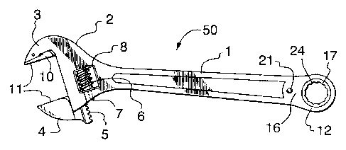
Figure 1 is a plan view of the present tool;
Figure 2 is a side elevational view of the tool of Figure 1;
Figure 3 is a partially sectional view of one end of the tool shown in Figure
2
through the line i-1;
-2-

CA 02186081 2002-11-28
Figure 4 is a perspective view of the end of the tool shown in Figure 3 less
the
ratcheting mechanism;
Figure 5 is a top plan view of an external socket for use with the wrench of
Figure 1;
Figure 6 is a side view of the socket of Figure 5; and
Figure 7 is a bottom plan view of the socket of Figure 5.
DESCRIPTION OF THE PREFERRED EMBODIMENTS
With reference initially to Figure 1, the present tool 50 comprises a handle
member 1 used to grip and operate the tool as either a pipe/crescent wrench or
as
a ratchet-operated socket wrench. A crescentlpipe wrench 2 is formed at one
end
of the handle with the socket wrench 16 being provided at the handle's
opposite end.
Crescent wrench 2 comprises a stationary upper jaw 3 which may include a
slidable
insert 10 including a plurality of teeth 11 functioning as pipe grips.
Opposite
stationary jaw 3 is a movable lower jaw 4. Movable lower jaw 4 is mounted for
lateral
movement in the manner of an adjustable crescent wrench. The movable lower jaw
4 is provided with a plurality of teeth 5 which are engaged by a worm gear 6
which
in turn is mounted for rotation on a laterally directed shaft 7. The worm gear
6 is
mounted in an opening 8 so that it is accessible for manual rotation from both
sides
of handle 1. The movable lower jaw 4 may also include a set of teeth 11 for
gripping
pipe.
At the other end of handle member 1 is as aforesaid a ratchet-operated socket
mechanism 16. Two flanges 12 and 13 respectively seen most clearly in Figure 4
extend from the body of handle member 1 at this end. The flanges provide
circular
apertures 14 and 15 respectively. Flanges 12 and 13 and their respective
apertures
14 and 15 form a cavity to receive ratchet-operated mechanism 16 including a
rotatable socket drive ring 17 having on its annular outer surface a plurality
of
incrementally spaced-apart ratchet teeth 18. These teeth are engaged by a pawl
19
(Figure 3) which is urged into operative relationship with the ratchet teeth
by a coil
spring 20. Drive ring 17 is held in place by flanges 12 and 13. As shown in
Figure
3, the ring 17 has an internal box 24 with points 34 to engage a fastener (not
shown)
-3-

CA 02186081 2002-11-28
directly or to engage sockets of various sizes as will be described below. A
fastener,
such as a rivet 21, passes through a suitable aperture 31 in handle member 1
and
passes through an axially aligned bore 22 in pawl 19 to act as the pawl's
pivot.
Handle member 1 is provided with a slot 23 extending rearwardly from the pawl
to
form an opening enclosing coil spring 20.
Laterally opposite annular flanges 25 on ring 17 extend through circular
apertures 14 and 15 formed in flanges 12 and 13, respectively. This locks the
drive
ring in place but also allows its rotation relative to the tool's handle.
As previously mentioned, socket drive 17 includes a box that can be sized to
directly engage fasteners of the same size. For greater flexibility, box 24 is
adapted
to engage variously sized sockets 26, an example of which is shown in Figures
5, 6
and 7. Sockets 26 may be conventional in shape and construction and are of
course
adapted to engage and drive various sized hex headed nuts or bolts. Socket
member 26 includes a male hex drive 27 to releasably engage box 24 in drive
ring
17. Each socket also includes a bowl 29 into which is formed a hex socket 30
of a
predetermined size and of course there will be a plurality of such sockets to
span a
predetermined size range for hex headed nuts and bolts. An annular shoulder 28
between male drive 27 and bowl 29 will bear against either of flanges 25 when
the
socket is fully engaged into drive ring 17.
The main elements of the present tool are castings or are formed by powder
metallurgy methods. The external sockets are preferably made from forged
steel.
The design of the elements is readily extrapolated to smaller and larger sizes
without
difficulty to provide a wide range of wrenches.
Handle member 1 is so formed that it can accomplish three functions relative
to the socket drive.
1. It acts as a housing bearing and raceway to limit and confine the
operation of the pawl relative to drive ring 17 as well as the rotation of the
ring itself
within the planar embrace of the handle.
2. When a socket is engaged with a fastener, the handle member 1 acts
as a lever to actuate the captive pawl through a slip movement about pin 21 to
a
selected locked position on the teeth of the ratchet; and
-4-

CA 02186081 2002-11-28
3. While the pawl holds the drive ring 17 in a locked position, it acts as a
lever to rotate the socket enough to twist tight or loosen the fastener hex
head held
fixed in the grip of the socket. Obviously, the socket is inserted into one
side or the
other of drive ring 17 for alternately tightening or loosening the fastener.
In addition, the construction used in this invention assures that the chamber
containing the drive ring and pawl mechanism may be periodically cleaned of
foreign
matter.
It is obvious that minor changes may be made in the form and construction of
the invention without departing from the material spirit thereof. It is not
however
desired to confine the invention to the exact form herein shown and described,
but
it is desired to include all such as properly come within the scope claimed.
-5-

Representative Drawing
A single figure which represents the drawing illustrating the invention.
Administrative Status

2024-08-01:As part of the Next Generation Patents (NGP) transition, the Canadian Patents Database (CPD) now contains a more detailed Event History, which replicates the Event Log of our new back-office solution.

Please note that "Inactive:" events refers to events no longer in use in our new back-office solution.

For a clearer understanding of the status of the application/patent presented on this page, the site Disclaimer , as well as the definitions for Patent , Event History , Maintenance Fee  and Payment History  should be consulted.

Event History

Description Date
Inactive: Expired (new Act pat) 2016-09-20
Letter Sent 2011-08-11
Inactive: Single transfer 2011-07-14
Inactive: Office letter 2003-03-20
Inactive: Prior art correction 2003-03-20
Inactive: S.8 Act correction requested 2003-02-20
Grant by Issuance 2003-02-11
Inactive: Cover page published 2003-02-10
Inactive: Final fee received 2002-11-28
Pre-grant 2002-11-28
Amendment After Allowance (AAA) Received 2002-11-28
Inactive: Entity size changed 2002-09-19
Notice of Allowance is Issued 2002-09-16
Letter Sent 2002-09-16
Notice of Allowance is Issued 2002-09-16
Inactive: Approved for allowance (AFA) 2002-07-26
Amendment Received - Voluntary Amendment 2002-06-10
Letter Sent 2002-01-15
Inactive: S.30(2) Rules - Examiner requisition 2002-01-10
Amendment Received - Voluntary Amendment 2001-11-30
Inactive: Single transfer 2001-11-30
Inactive: S.30(2) Rules - Examiner requisition 2001-07-31
Amendment Received - Voluntary Amendment 2001-03-23
Inactive: Application prosecuted on TS as of Log entry date 2000-11-23
Inactive: S.30(2) Rules - Examiner requisition 2000-11-23
Inactive: Status info is complete as of Log entry date 2000-11-23
Letter sent 2000-11-15
Advanced Examination Determined Compliant - paragraph 84(1)(a) of the Patent Rules 2000-11-15
Request for Examination Received 2000-11-02
Request for Examination Requirements Determined Compliant 2000-11-02
Inactive: Advanced examination (SO) fee processed 2000-11-02
All Requirements for Examination Determined Compliant 2000-11-02
Early Laid Open Requested 2000-11-02
Inactive: Advanced examination (SO) 2000-11-02
Inactive: Cover page published 1999-09-30
Application Published (Open to Public Inspection) 1998-03-21
Small Entity Declaration Determined Compliant 1996-09-20

Abandonment History

There is no abandonment history.

Maintenance Fee

The last payment was received on 2002-09-11

Note : If the full payment has not been received on or before the date indicated, a further fee may be required which may be one of the following

  • the reinstatement fee;
  • the late payment fee; or
  • additional fee to reverse deemed expiry.

Please refer to the CIPO Patent Fees web page to see all current fee amounts.

Owners on Record

Note: Records showing the ownership history in alphabetical order.

Current Owners on Record
PROXENE TOOLS CO., LTD.
Past Owners on Record
RONALD YERYK
Past Owners that do not appear in the "Owners on Record" listing will appear in other documentation within the application.
Documents

To view selected files, please enter reCAPTCHA code :


To view images, click a link in the Document Description column. To download the documents, select one or more checkboxes in the first column and then click the "Download Selected in PDF format (Zip Archive)" or the "Download Selected as Single PDF" button.

List of published and non-published patent-specific documents on the CPD .

If you have any difficulty accessing content, you can call the Client Service Centre at 1-866-997-1936 or send them an e-mail at CIPO Client Service Centre.


Document
Description 
Date
(yyyy-mm-dd) 
Number of pages   Size of Image (KB) 
Representative drawing 2003-01-07 1 10
Cover Page 2003-01-07 1 34
Description 2003-03-20 5 230
Claims 2003-03-20 1 49
Drawings 2003-03-20 2 32
Abstract 1996-09-20 1 16
Cover Page 1996-09-20 1 14
Claims 1996-09-20 1 35
Description 1996-09-20 5 228
Drawings 1996-09-20 3 35
Cover Page 1998-03-26 1 35
Description 2002-11-28 5 233
Abstract 2002-11-28 1 15
Claims 2002-11-28 1 49
Drawings 2002-11-28 2 33
Cover Page 1999-09-30 1 35
Description 2001-11-30 5 233
Claims 2001-11-30 1 43
Representative drawing 1998-03-26 1 6
Representative drawing 2002-09-05 1 7
Reminder of maintenance fee due 1998-05-21 1 111
Courtesy - Certificate of registration (related document(s)) 2002-01-15 1 113
Commissioner's Notice - Application Found Allowable 2002-09-16 1 163
Courtesy - Certificate of registration (related document(s)) 2011-08-11 1 102
Correspondence 2003-02-20 1 36
Correspondence 2003-03-20 1 9
Fees 2003-06-19 1 34
Correspondence 2002-11-28 2 60
Correspondence 2000-11-02 2 76
Fees 2001-09-17 1 37
Fees 2002-09-11 1 36
Fees 1998-06-02 1 48
Fees 1999-06-08 1 36
Fees 2000-06-07 1 36
Fees 2004-06-04 1 41
Fees 2005-06-20 1 33
Fees 2006-08-11 1 36
Fees 2007-08-07 1 59
Fees 2008-09-17 1 63
Fees 2009-07-16 1 49
Fees 2010-08-19 7 271
Fees 2011-08-26 1 45