Note: Descriptions are shown in the official language in which they were submitted.
WO 95/26055 2 1 8 :6 1 ~ 2 PCT/SE95/00299
LEAD BATTERY
This invention concerns batteries according to the respective
preambles of the claims 1, 12, 17, 22.
The electrodes in a lead acid battery are formed by current
conducting lead grids being filled with active lead material.
Positive material is named PAM and negative material NAM. The
most common type of electrodes are those called ~pasted" plates
having the current conductor designed as a grid. Between the
positive and negative electrodes, or the "plates", porous
separators are placed. Usually several positive and negative
electrodes are mutually connected in parallel to form a "group
of plates" or a cell. The current passes from the electrodes
via current conductors in the upper part of the electrodes, so
called lugs which are soldered to ~bars~, which are connected
to the so called terminals. The cells are usually connected in
series to form batteries with higher voltages.
During the discharge, PbSO4 with larger volume than Pb and PbO2
is formed within the electrodes. During discharges without any
support of the electrodes, the active material will expand.
This volume expansion is permanent if a resilient counter
pressure is not applied. During each new discharge there is a
certain increase of volume, the paste will crack and after a
number of discharges positive paste (PAM) will fall out from
the electrode, (the grid).
There is no corrosion within the negative electrodes . Thus
only a moderate mechanical support is needed to get an almost
reversible process. The surface of the positive lead grid is
formed to PbO2. The PbO2 thus formed takes up a larger volume
than the lead from which it is formed and strain will occur in
the corrosion layer. During successive discharges there is some
discharge of the PbO2 on the grid surface and because of the
volume growth cracks will occur, more lead is formed to PbO2
and the grids will corrode.
The experience shows that mechanical pressure on the electrode
wossl26o55 ~l 8 ~ 1 6 2 PCT~SEg5~00299
surfaces will increase the working life. Batteries with so
called pasted plates thus often comprise glass wool between the
electrodes, and the cells are assembled into blocks with
mechanical pressure against the cell walls and thereby also on
the electrode surfaces. This pressure is maintained by assemb-
ling the groups into cell containers under pressure or into
blocks of cell containers (starting batteries) having enough
strength to counteract the volume increase.
In order to obtain at long working life, the positive active
material, PAM, in batteries intended for longer discharges
comprises high density i.e. low porosity with correspondingly
lower material utilisation and thus lower capacity.
In so called tubular batteries the current conductor of the
positive electrode consists, unlike in pasted plates, of
parallel lead rods surrounded by active positive material which
in turn is mechanically supported by surrounding porous tubes.
The material of the tubes usually is comprised of braided or
woven glass fibres. The diameter of these tubes is usually
between 8-10 mm defining the width of the electrode. These
positive electrodes are called "tube plates". One reason for
tubular batteries with tubes of glass fibres having high paste
porosity, i.e. low density, and thus good paste utilisation and
yet long life, is that the paste is allowed to expand somewhat
in the tubes by elastic elongation of the glass wool fibres and
increasing tube diameter. This can cause more than 10% increase
of volume during discharge. During charge the strained glass
wool fibres return the volume of the positive paste to its
state before the discharge. The strength of the glass fibres
will however be reduced during the time.
WO 85/05227 (Sundberg) concerns a device having semi-tubes,
however without support in all directions. Also the lug lacks
support.
Also in batteries with pasted plates the compressed and rela-
wossl26oss 21 8~61 :62 PCT/~55lo^259
tively thick glass wool, which often is used as the separator,
has a certain resilient effect. In batteries having rectangular
containers this pressure exercised against the flat cell walls
is insufficient to counteract the expansion. The free volume
above and below the electrodes allow some expansion, and since
` the electrodes are not entirely supported by the walls of the
container, they can also grow somewhat in width. The battery
according to US-A-4 336 314 has rectangular plates which
however lack support for upper and lower electrode sides.
DE-2 758 288 concerns a sealed oxygen recombination cell but
does not mention support for electrode sides.
Also in known batteries having the cells essentially entirely
enclosed inside a plastic material, the resilience of the flat
walls will bring about insufficient support (JP 59-98476 and
60-74360).
The problems with the known batteries are solved by the
features according to the characterizing portions of the
independent claims.
According to this invention which concerns lead batteries with
long working life, all the outer surfaces of the electrodes are
put under high mechanical pressure and the projected electrode
surface is maintained unchanged through absolute support from
all sides.
The invention will now be described in light of embodiments and
with reference to the drawings, wherein:
fig 1 shows an embodiment of the invention according to the
- lnventlon,
fig 2 shows an electrode with a lug,
fig 3 shows an electrode with detail in an enlarged scale,
WO 95/260S5 . PCTISE95/00299
4 2~`8`~1 62
fig 4 shows an electrode pile,
fig 5a, b and c show different arrangements for securing the
positive material,
fig 6 shows a two cell battery according to the invention,
fig 7 illustrates a principle with respect to rectangular
plates, and
fig 8a, b and c show volume filling arrangements inside a
battery container.
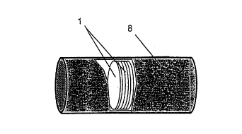
One example of obtaining such a support is illustrated in fig
1. Here the electrodes 1 in fig 1 are assembled in tubular,
constant volume containers 8 which, through the cell container
(fig 1) or the support from an outer container (13 in fig 6)
support the circumferences of the electrodes (in first
directions, which by the container or the vessel is defined as
radial directions) in order to get an unchanged electrode
surface area. Through high mechanical pressure on the electrode
surface (in a second direction, which is defined by the
container or the vessel as axial) and constant volume of the
electrode group, the working life can be maximised since the
corrosion during charging is controlled. Higher pressure limits
the depth of the discharge. During the discharge, lead sulphate
is formed which comprises essentially larger volume than the
PbO2. When the pores in the positive electrodes are filled with
lead sulphate and the expansion is prevented by an outer
counter pressure, no more electrolyte can diffuse into the
electrode and the discharge is terminated.
With sufficient pressure and support, the expansion stops and
the corrosion decreases. Because of an absolutely unchanged
volume the working life will be multiplied.
The corrosion of positive lead grids can not be avoided, since
woss/26o55 5 ~1 8 h 1 ~ 2 PCT/SEgS/00299
the grids have a possibility of a volume increase at the
expense of the volume of the porous active material. Compressed
PbO2 has, however, a significantly better current conductivity
than the porous paste, and the PbO2 which is formed by grid
S corrosion has a high density and a good electric conductivity:
about 1/10 of that of lead. It is known that completely
corroded lead spines in tubular batteries, where the pressure
in the tubes is high, may act as current conductors during many
years, giving the battery good capacity at not too high loads.
In the same way these volume controlled batteries, where the
whole group is under high mechanical pressure, obtain a very
long life and function with full capacity during many thousand
discharges also with completely corroded current conductors.
Also a new battery can be made without the lead grid. Thus a
thin lead foil is firstly formed to PAM, and already during the
formation the lead corrodes to PbO2. In order to handle the
plates during manufacture, a plastic grid may be used. Use of
plastic grids in negative electrodes is previously known.
The pressure on the positive electrode surfaces can be
resilient (spring action), since a small expansion of the paste
during discharge can be allowed without influencing the working
life of the material, provided the pressure on the electrode
surface is sufficiently high so that the volume retains its
original volume after a discharge and the subsequent charge.
Without this expansion the supply of electrolyte to the active
material in the electrode will decrease when the pores of the
paste are filled with lead sulphate and thus the capacity will
be reduced.
- In a battery under pressure according to the invention a con-
trolled expansion of the paste during discharge and compression
during charge can be obtained by resilient separators or by a
resilient element, e. g. a rubber seal being placed in the
cells or in the batteries, and providing pressure on the
electrode surface.
w095/260s5 2 1 8 ~ 1 6~2 PCT/SE95,00299
This effect has been applied in certain tubular batteries with
elastic tubes and to some extent in pasted batteries with
flexible separators, but the effect is significantly better in
a construction with fix, unchanged electrode area according to
the invention. The active material is allowed to expand during
the discharge only perpendicular to the surface of the
electrode (in the second or axial direction) and not in the
plane of the electrode (in the first or radial directions).
During the charge the expansion is pressed back. A certain
resilient effect can be obtained with separators made from
relatively thick, compressed glass wool and this is part of
this invention.
With the high pressure on the pasted surface in batteries
according to the invention, the expanding property of ordinary
glass wool is not always sufficient and an extra spring load on
the electrode group may be necessary.
In order to fully regulate and limit the discharge, the
pressure on the electrode surfaces must be high, from 0.5 up to
10 kptcm2 (0.49 -105 - 9 . 81 -105 Pa), or higher. The pressure on
the electrode surface will determine also the depth of the
discharge, because of the volume increase limitation and thus
the supply of electrolyte. The pressure is limited to what the
separators can withstand before breaking. If springs are used
to control the volume, it is easy to vary the pressure
according to the application, (desired capacity) by using
springs with different spring constant. Less pressure may lead
to higher capacity, but also shorter life. In a battery
according to the invention directed to having long working
life, a mechanical pressure of 0.98 -105 - 9 . 81 -105 Pa is
preferred and in a battery directed to high capacity a
mechanical pressure of 0.49 -105 - 0 . 98 -105 Pa. Expansion, i.e.
the increase of the electrode thickness, of up to 15% is
possible with the corresponding shrinking during charge.
To be able to prevent the surface area of the electrode to
W095/26055 2 ~ ~ ~ 1 62pCT~SE9s~-25~
increase, an outer container with constant volume e.g. a steel
or composite tube is used and the cells are made with
preferable almost circular plates, fig 2, and the cell group
will have the shape of a tube, fig l.
s
By the high pressure of porous glass wool against the electrode
surfaces, no paste can leave the electrode and no extra space
(sludge volume) for fallen out material is needed. The cells
will therefore have a smaller volume than corresponding cells
according to the previous art.
In cells according to the invention, the circular electrodes
may have one or more "lugs" 3, more like low ridges, on the
sides. These lugs may extend over almost the half circumference
for the best current distribution. The lugs with connections
are included in the circular electrode. Fig 3 shows an
electrode l which has the grid filled with active paste
material 4'. The electrode is provided with a current connector
in the form of a lug 3. In order to prevent short circuits the
circumferences of both the positive and the negative electrodes
are protected by a U-profile 5 of a plastics material which
envelopes the edges of the electrodes or the electrode paste
according to fig 3, 4, 5. If the frames of the electrode are
made from a plastics material, the U-profile is not always
necessary.
The wall thickness of the U-profile may be thin, preferably
O.l-0.3 mm and a thickening of the plate at the edges by some
tenth of a mm will appear. This thickening will however be
pressed into the separators and is in general of no concern. If
stronger profile is desired, it can be put onto the lead grid
- before the application of the active paste 4', 4'', so that the
U-profile then determines the thickness of the electrode as
shown in fig 5. At the current connector, the lug 3, the
U-profile 5 may have a recess, so that the lugs 3 from the
positive and the negative plates protrude, as is shown in
figure 4, through the U-profile, such that they can then be
WO 95/26055 2 1 8 6 1 6 2 PCT/SE95/00299
welded to a current conductor bar 6 in Figure 6.
The positive and negative lugs are preferable arranged opposite
to each other and the positive and negative current connector
lugs 3 are situated at the opposite sides of the cell, and this
construction is part of the invention. Fig 6 shows a twin cell
battery. The coupling, i.e. the connection 7 to the next cell
is therefore also provided at opposite sides. The conductor 7
can have the shape of an expansion coil to allow some
movability. The lugs 3 are welded to the bar 6 which is
embedded in the container wall 8. A spring 9 compresses the
cells. It may suitably be made from resilient soft rubber only
and be placed 10 between two cells thus exerting pressure on
both cells. Alternatively a spring 9 and a resilient rubber
means 10 between the cells are combined as is shown in fig 6.
The cell walls are thin and the cells are placed in an outer
constant volume container 13.
The description and the figures illustrate examples of
constructions according to the invention.
Circular cylindrical batteries most easily take up the pressure
without change of volume and may therefore have thin walls.
If the containers are rigid enough, the electrodes and the
cross section of the cells may have other forms, e.g.
rectangular. Ordinary starting battery plates may be used
resulting in a very long life battery, the same as or better
than the tubular batteries of today. To obtain better current
distribution these rectangular plates 12 may have the lugs 3
located opposite to each other and have two or three lugs or
one lug as wide as the electrode, fig 7, and being having as
small height as possible. The profiles 5 surround the
electrodes on all sides, however the profiles are provided with
apertures in the profile where the lugs protrude, and are
assembled with a support all around the electrode from the
container wall. In a similar way as with circular electrodes
w095/260s5 2 ~ 1 6 ~ PCT/SE9SI'~253
the separators 2 are placed between the electrodes.
It should be noted that by "first or radial directions" is
intended directions from the periphery and inwards, also for
S electrodes with other forms than circular. By "a second or
~ axial direction" is intended a direction perpendicular to the
first directions, i.e. in a length direction of an electrode
pile.
If the containers are mechanically week, they can, as is shown
in fig 6, be fitted exactly into a rigid outer container with
constant volume 13, and since each single plate is supported by
the walls of the cell, the circumference of the electrodes will
be maintained during discharge without possibility of expanding
in any direction, whilst the thickness of the electrode is
controlled by resilient pressure.
If rectangular electrodes are used (starting battery plates),
they may be enclosed into rectangular tubes with constant
volume. Circular tubes may however be made essentially lighter
at high pressure and therefore rectangular electrodes may be
enclosed into circular tubes if the electrodes are supported on
all four sides by supporting profiles 15 which contact the
outer container 13 as is shown in fig 8A, B.
The supporting profiles 18' may be slotted and perforated,
fig 8B, C and comprise cavities with for example extra
electrolyte absorbing glass wool 19 in order to create extra
acid volume. Porous separators 2 saturated with electrolyte may
be made larger than the electrodes and contact the plastic
support and extend to the outer wall. The electrolyte volume
- becomes larger without increasing the electrode distance. The
outer container 13 may be made of steel for easier cooling.
According to the above, the conductors 6 can be provided with
an expansion coil if a certain expansion of the electrode
during the discharge is desired.
w095/260ss ~ 6 2 PCT~SE9sloo299
Ordinary lead grids for conduction of current and securing the
paste, fig 5A, have staggered grids 14 for better securing the
paste and are in that case provided with a lead frame 15 around
the grid. The high pressure in the batteries according to the
invention allows the positive electrode to be made simply from
a grid, which has been punched out from a lead foil 16 as
current conductor, fig 5C. The U-profile 5 determines the
thickness of the positive active material 4' on each side of
the lead conductor. The grid in the positive plate corresponds
to the lead spines in the tubular battery, i.e. they are
centrally placed in the electrode and completely covered by the
electrode paste. Since the current conductor also after having
been completely reformed to PbO2 shall work with reasonable low
resistance, the thickness shall not be to small compared to the
lS plate thickness.
The absolute limitation and control of the volume according to
the invention will allow the electrodes in power batteries to
be made very thin, in certain cases 0.5 mm or less, with active
material received from so called Plante' formation of the lead
in the positive electrode. Because of the high pressure and the
current connectors being placed opposite to each other, these
batteries will have an even current distribution which is very
important with respect to a current conductor converted to
PbO2. The electrodes in these cells should have an extra high
pressure for maximum conductivity of PbO2 in the current
conducting parts.
In order to obtain entirely closed cells with high so called
oxygen recombination, the pressure of the liquid in the cells
shall be high, 4 - 10 atm or higher. At this pressure the
solubility of the oxygen is so high that the oxygen which is
formed during charging, before the hydrogen, in its soluted
form oxidises the negative plate, which therefore is not fully
charged and hydrogen gas formation is prevented. With the
mechanical strength of the cells according to the invention
such liquid pressure may easily be maintained. This high liquid
WO 95/26055 2~1 8 61 6 2 PCT/SE95/00299
11
pressure is also part of the invention.
In order to decrease the gas pressure in the case of maltreat-
ment, the cells have been provided by safety valves.