Note: Descriptions are shown in the official language in which they were submitted.
-1-
2~ 861 86
TITLE OF THE INVENTION
BROADBAND ANTENNA USING A SEMICIRCULAR RADIATOR
BACRGROUND OF THE INVENTION
The present invention relates to an antenna that has a
s bandwidth as broad as 0.5 to 13 GHz, for example, but is
small in size and, more particularly, to an antenna using a
semicircular radiator or semicircular, ribbon-shaped
radiator.
In R.M. Taylor, "A Broadband Omnidirectional Antenna,"
1o IEEE AP-S International Symposium, 1994, p1294, there is
disclosed a conventional broadband antenna using
semicircular conductor discs as depicted in Fig. 1. This
conventional antenna has two elements. One of the elements
is composed of two semicircular conductor discs 1218 and
15 122x, which have a common center line Ox passing through the
vertexes of their semicircular arcs and cross at right
angles. The other element is also composed of two elements
121b and 122b, which similarly have a common center line Ox
passing through the vertexes of their semicircular arcs and
2o cross at right angles. The two elements are assembled with
the vertexes of their circular arcs opposed to each other.
A feeding section is provided between the vertexes of the
arcs of the two elements; a coaxial cable 31 for feeding is
disposed along the center of one of the two elements, with
25 the outer conductor of the cable held in contact with the
element.
~~:,a.
286186
-2-
Fig. 2 illustrates a simplified version of the antenna
depicted in Fig. 1, which has semicircular conductor discs
12a and 12b disposed with the vertexes of their semicircular
arcs opposed to each other. The feeding section is provided
between the vertexes of the two conductor discs 12a and 12b
to feed them with the coaxial cable 31 installed in the
conductor disc 12b.
Fig. 3 shows the vSWR characteristic of the antenna
depicted in Fig. 2. It will be seen from Fig. 3 that the
1o simplified antenna also has a broadband characteristic,
which was obtained when the radius r of each of the
semicircular conductor discs 12a and 12b was chosen to be 6
cm. The lower limit band with vSWR<2.0 is 600 MHz. Since
the wavelength ~, of the lower limit frequency in this
instance is approximately 50 cm, it is seen that the radius
r needs to be about (1/8)7. The radiation characteristic of
the antenna shown in Fig. 1 is non-directional in a plane
perpendicular to the center line Ox, whereas the radiation
characteristic of the antenna of Fig. 2 is non-directional
2o in a frequency region from the lower limit frequency to a
frequency substantially twice higher than it and is highly
directive in the same direction as the radiator 12a in the
plane perpendicular to the center line Ox.
Thus, the conventional antenna of Fig. 1 comprises upper
and lower pairs of antenna elements each formed by two
_3_ 2186186
sectorial radiators crossing each other, and hence it
occupies much space. Also in the simplified antenna of
Fig. 2, the sectorial semicircular radiators are space-
consuming. In terms of size, too, the conventional
antennas require semicircular conductor discs whose radii
are at least around 1/8 of the lowest resonance
wavelength; even the simplified antenna requires a 2r by
2r or (1/4)~ by (1/4)~ antenna area. Accordingly, the
conventional antennas have defects that they are bulky and
space-consuming and that when the lower limit frequency is
lowered, they become bulky in inverse proportion to it.
SUMMARY OF THE INVENTION
It is therefore an object of the present invention to
provide an antenna which has the same electrical
characteristics as in the prior art but is less bulky, or
an antenna which is smaller in size and lower in the
lowest resonance frequency than in the past.
In accordance with one aspect of the present invention
there is provided an antenna comprising: a first radiator
formed by a substantially semicircular conductor disc,
said first radiator defining a substantially semicircular
cutout concentrically therewith to form a semicircular
arc; a plane conductor ground plate disposed opposed to
the semicircular arc of said first radiator at right
angles thereto; and a feeder connected to the vertex of
the semicircular arc of said first radiator and said plane
_4_ 2186186
conductor ground plate, for feeding power across said
first radiator and said plane conductor ground plate.
In accordance with another aspect of the present
invention there is provided an antenna comprising:
a first radiator formed by a substantially semicircular
arcwise conductor with a semicircular cutout defined
concentrically therewith to form a semicircular arc; a
second radiator formed by a substantially semicircular
conductor disc and disposed with the vertex of said
semicircular conductor disc opposed to the vertex of the
semicircular arc of said first radiator; and a feeder
connected to said vertexes of said first and second
radiators, for feeding power across said first and second
radiators.
In accordance with yet another aspect of the present
invention there is provided an antenna comprising: a
radiator formed by a substantially semicircular conductor
disc bent into a cylindrical shape; a plane conductor
ground plate disposed opposite and apart from the vertex
of the semicircular arc of said radiator at substantially
right angles to the generating line of said cylindrical
shape; and a feeder connected to the vertex of said
semicircular arc of said radiator and said plane conductor
ground plate, for feeding power across said radiator and
said ground plate.
-4a- 2 1 8 61 8 6
In accordance with still yet another aspect of the
present invention there is provided an antenna comprising:
a radiator formed by a substantially semicircular
conductor disc bent into a cylindrical shape; another
radiator formed by another semicircular conductor disc
having a center line aligned with that of said
semicircular conductor disc of said radiator, said another
semicircular conductor having a vertex opposed to a vertex
of the semicircular arc of said radiator apart therefrom;
and a feeder connected to the vertexes of the semicircular
arcs of said radiator and said another radiator, for
feeding power across said radiator and said another
radiator.
-5- 2186186
With the antennas according to the various aspects
of the invention, it is possible to reduce the space
for the antenna element while retaining the same broadband
characteristic as in the past, by defining the semicircular
s notch in the semicircular radiator to form the arcwise
radiator and/or bending the semicircular or arcwise radiator
into a cylindrical form. Furthermore, by incorporating
another radiating element in the notch of the semicircular
radiator, it is possible to achieve a multi-resonance
1o antenna without upsizing the antenna element, and the VSWR
characteristic can be improved as compared with that in the
prior art by bending the semicircular radiator into a
cylindrical form.
BRIEF DESCRIPTION OF THE DRAWINGS
15 Fig. 1 is a perspective view of a conventional antenna;
Fig. 2 is a perspective view showing a simplified
version of the antenna of Fig. 1;
Fig. 3 is a graph showing the VSWR characteristic of the
antenna depicted in Fig. 2;
2o Fig. 4 is a perspective view of an antenna structure on
which the present invention is based;
Fig. 5A is diagram showing the current density
distribution on a radiator of the antenna structure of Fig.
4;
2s Fig. 5B is a graph showing the VSWR characteristics
obtained with radiators of different shapes in the Fig. 4
_ ~ 186186
structure;
Fig. 6 is a perspective view illustrating a first
embodiment of the present invention;
Fig. 7 is a diagram showing one mode of feeding in Fig.
6;
Fig. 8 is a diagram showing another mode of feeding in
Fig. 6;
Fig. 9 is a diagram showing still another mode of
feeding in Fig. 6;
to Fig. l0A is a front view of the Fig. 6 antenna structure
on which experiments were conducted;
Fig. lOB is its plan view;
Fig. lOC is its side view;
Fig. 11 is a graph showing the measured VSWR
characteristic;
Fig. 12 is a perspective view illustrating a second
embodiment of the present invention;
Fig. 13 is a perspective view illustrating a third
embodiment of the present invention;
2o Fig. 14 is a graph showing the VSWR characteristic of
the antenna depicted in Fig. 13;
Fig. 15 is a perspective view illustrating a fourth
embodiment of the present invention;
Fig. 16 is a perspective view illustrating a fifth
embodiment of the present invention;
Fig. 17 is a perspective view illustrating a sixth
-'- 2~s 86186
embodiment of the present invention;
Fig. 18 is a graph showing the VSWR characteristic of
the antenna depicted in Fig. 17;
Fig. 19 is a graph showing the low-frequency region on
s an enlarged scale in Fig. 18;
Fig. 20 is a diagram illustrating a modified form of the
Fig. 16 embodiment;
Fig. 21 is a diagram illustrating another modification
of the Fig. 16 embodiment;
1o Fig. 22 is a diagram illustrating still another
modification of the Fig. 16 embodiment;
Fig. 23 is a perspective view illustrating one mode of
carrying out the sixth embodiment of the present invention;
Fig. 24 is a perspective view illustrating another mode
15 of carrying out the sixth embodiment of the present
invention;
Fig. 25 is a perspective view illustrating an example of
the structure for feeding in the present invention;
Fig. 26 is a perspective view illustrating another
2o example of the structure for feeding;
Fig. 27 is a perspective view illustrating still another
example of the structure for feeding;
Fig. 28 is a perspective view of a seventh embodiment of
the present invention;
25 Fig. 29A is a front view of an antenna used for
experiments of the seventh embodiment of the present
-8- 2186186
invention;
Fig. 29B is its plan view;
Fig. 29C is its right-hand side view;
Fig. 29D is a development of a radiator 13;
s Fig. 30 is a graph showing the measured VSWR
characteristic of the antenna of Figs. 29A to 29D;
Fig. 31 is a graph showing the VSWR characteristics
measured for different axial lengths of the elliptic
cylindrical radiator in Fig. 28;
1o Fig. 32 is a diagram for explaining the distance between
opposite ends of a semicircular radiator bent into a
cylindrical form;
Fig. 33 is a graph showing the VSWR characteristics
measured for different distances between the opposite ends
i5 of the cylindrical radiator by changing the diameter of its
cylindrical form;
Fig. 34 is a graph showing the VSWR characteristics
measured in the cases where the opposite ends of the
semicircular radiator are electrically connected and
2o isolated, respectively;
Fig. 35 is a perspective view illustrating an eighth
embodiment of the present invention;
Fig. 36A is a front view of an antenna used for
experiments of the eighth embodiment of the present
25 invention;
Fig. 36B is its plan view;
_9_ 2186186
Fig. 36C is its right-hand side view;
Fig. 36D is a development of a radiator 14;
Fig. 37A is a graph showing the VSWR characteristic of
the antenna of Figs. 36A to 36D;
Fig. 37B is a graph showing, by way of example, the
relationship between the area ratio of a cutout to the
radiator and the worst VSWR characteristic in the operating
region;
Fig. 38 is a perspective view illustrating a ninth
1o embodiment of the present invention;;
Fig. 39A is a front view of an antenna used for
experiments of a tenth embodiment of the present invention;
Fig. 39B is its plan view;
Fig. 39C is its right-hand side view;
i5 Fig. 40 is a graph showing the measured VSWR
characteristic of Figs. 39A to 39D;
Fig. 41 is a graph showing the low-frequency region on
an enlarged scale in fig. 40;
Fig. 42 is a diagram illustrating a modified form of the
2o tenth embodiment;
Fig. 43 is a diagram illustrating another modification
of the tenth embodiment; and
Fig. 44 is a diagram illustrating still another
modification of the tenth embodiment.
25 DESCRIPTION OF THE PREFERRED EMBODIMENTS
To facilitate a better understanding of the present
Y
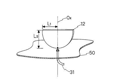
_lo_ 218 618 6
invention, a description will be given first of a monopole
antenna which comprises a semicircular radiator disc, which
is one of the radiating elements of the dipole antenna shown
in Fig. 1, and a plane conductor ground plate serving as a
s mirror image plane and is equivalent in operation to the
antenna of Fig. 1. As shown in Fig. 4, the monopole antenna
was formed by placing a semiconductor radiator 12 on a plane
conductor ground plate 50 vertically thereto with the vertex
of the circular arc of the former held in adjacent but
to spaced relation to the latter and connecting center and
outer conductors of a coaxial feeding cable to the vertex of
the circular arc of the semicircular radiator 12 and the
ground plate 50, respectively. And, as described just
below, analyses were made of the monopole antenna shown in
15 Fig. 4. Since the conductor ground plate 50 forms a mirror
image of the radiator 12, the operation of this monopole
antenna is equivalent to the operation of the antenna
depicted in Fig. 2.
(a) The distribution of a 5 GHz high-frequency current
20 on the radiator 12 was analyzed by a finite element method,
from which it was found that high current density regions
developed discontinuously along the circumference of the
semicircular radiator 12 as shown by hatched areas in Fig.
5A, whereas the current flow in the central region was
2s negligibly small--this indicates that the arcwise marginal
area of the semicircular disc contributes largely to
-11-
2186186
radiation.
(b) The shape of the semicircular radiator 12 in Fig. 4
was defined generally as an ellipse inclusive of a circle
and the influence of the dimensional relationship between
s perpendicularly intersecting first and second radii L1 and LZ
of the radiator 12 on the VSWR characteristic was measured
under the three conditions listed below.
(1) L1 = L2 = 75 mm (i.e. In the case of a semicircle)
(2) L1 = 75 mm, L2 = 50 mm (i.e. When L1 > L2)
(3) L1 = 40 mm, L2 = 75 mm (i.e. When L1 < L2)
In Fig. 5B there are shown the VSWR characteristics measured
under the above-said three conditions, which are indicated
by the solid, broken and thick lines 5a, 5b and 5c,
respectively. From Fig. 4 it is seen that a change in the
1s radius L2 causes a change in the lower limit frequency of the
band (a decrease in the radius L2 increases the lower limit
frequency) but that even if the semicircular form of the
radiator is changed to an ellipse, no significant change is
caused in the VSWR characteristic--this indicates that the
2o radiator 12 need not always be perfectly semicircular in
shape.
Based on the results of the analysis (a), a semicircular
area of the semicircular radiator disc inside the arcwise
marginal area thereof is notched to define a semicircular
25 cutout, which is used to accommodate another antenna element
-12- 2~ 8s~ 8s
or an electronic part or circuitry.
According to the results of the analysis (b), the vSWR
characteristic remains substantially unchanged regardless of
whether the radiator is semicircular or semi-elliptic. This
s applies to an arcwise ribbon-shaped radiating conductor for
use in the embodiments of the present invention described
hereinbelow.
FIRST EMBODIMENT
Fig. 6 is a perspective view illustrating the antenna
1o structure according to a first embodiment of the present
invention, which comprises a pair of substantially
semicircular arcwise radiators lla and llb (made of copper
or aluminum, for instance). The outer and inner marginal
edges of each arcwise radiator 11 may be semicircular or
15 semi-elliptic. The two radiators lla and llb are disposed
with vertexes 21a and 21b of their circular arcs opposed to
each other and a feeding section 30 is provided between the
vertexes 21a and 21b. The two semicircular arcwise
radiators 11a and llb have centrally, substantially semi-
20 circular cutouts 41a and 41b concentric therewith. In
the case where the radiators lla and llb are semicircular
and the cutouts 41a and 41b are semi-ellipses each having
the major axis, for example, in the horizontal direction,
the widths W of radiators lla and llb gradually decrease or
25 increase toward their both ends. When the cutouts each have
the major axis in the vertical direction, the widths W of
-13- 21 861 86
the radiators lla and llb gradually increase toward their
both ends. This antenna structure permits placement of
other elements in the cutouts 41a and 41b, and hence it
provides increased space factor as compared with the
s conventional antenna using completely semicircular conductor
discs.
Figs. 7 through 9 show, by way of example, different
feeding schemes for the antenna of the Fig. 4 embodiment.
In Fig. 7 the coaxial cable 31 is disposed along the center
line Ox of the radiator llb, whereas in Fig. 8 the coaxial
cable 31 is disposed along the semicircular outer periphery
of the radiator llb. In Fig. 9 a twin-lead type feeder 33
is used. In any case, feeding is carried out between the
vertexes 21a and 21b of the two radiators lla and llb.
1s An experiment was conducted to verify or determine the
performance of the antenna of this embodiment. Fig. 10
shows its front, right-hand side and plan views, and Fig. 11
shows the VSWR characteristic measured in the experiment.
In the experiment the outside shape of each of the radiators
lla and llb was a semicircle with a radius a=75 mm and the
shape of each of the cutouts 41a and 41b was a semicircle
concentric with the outside shape of each radiator and
having a radius b=55 mm. Accordingly, the widths W of the
radiators lla and llb were 20 mm. The coaxial cable 31
disposed along the center axis of the radiator llb was used
for feeding, the coaxial cable 31 having its center
-14- 21 8 61 8 6
conductor connected to the vertex 21a of the radiator lla
and its outer conductor connected to the other radiator llb.
Comparison of the VSWR characteristic thus obtained with the
VSWR characteristic of the prior art example shown in Fig. 3
indicates that the VSWR is limited to about 2 or smaller
value in a fFequency region above 600 MHz and that the band
characteristic is about the same as that of the prior art
example regardless of the cutouts of the radiators. The
provision of the cutouts enhances the space factor because a
to circuit device, another radiating element or the like can be
placed in the cutout of each radiator.
SECOND EMBODIMENT
Fig. 12 illustrates in perspective the antenna structure
according to a second embodiment of the present invention.
The antenna of this embodiment is provided with two sets of
antenna elements, one of which is composed of a pair of
substantially semicircular conductor discs 121b and 122b such
as described previously with reference to the prior art
example of Fig. 1. The conductor discs 121b and 122b cross
2o at right angles, with the vertexes of their circular arcs
held at the same position and their center lines virtually
aligned with each other. The other set of antenna elements
is composed of a pair of semicircular arcwise radiators llla
and 112x, each of which is substantially semicircular and has
a cutout defined centrally thereof as described above with
A
-15- 21 8 61 8 6
reference to Fig. 6. The radiators 111a and 112a also cross
at right angles, with the vertexes of their circular arcs
held at the same position as indicated by 21a and their
center lines Ox aligned with each other. The two sets of
s antenna elements are combined, with the vertexes 21a and 21b
of the radiators 111x, 112a and 121b, 122b opposed to each
other, the vertexes 21a and 21b being used as feeding
points. In this example, the coaxial cable 31 is used for
feeding, which has its center conductor connected to the
io vertex 21a and its outer conductor connected to the vertex
21b. A twin-lead type feeder or the like can be used in
place of the coaxial cable 31.
The antenna structure of this embodiment also provides
the same broadband characteristic as is obtainable with the
15 prior art example of Fig. 1. Accordingly, this embodiment
is excellent in space factor as is the case with the first
embodiment, and by using a plurality of radiators to form
the radiating element, the directivity in the horizontal
plane can be made omnidirectional.
20 THIRD EMBODIMENT
Fig. 13 illustrates in perspective a third embodiment of
the present invention, which is a monopole antenna
corresponding to the dipole antennas shown in Figs. 6 and 7.
The antenna of this embodiment is composed of a
2s substantially semicircular arcwise radiator 11 having a
yvirtually semicircular cutout 41 defined centrally thereof
-16- 2186186
and a plane conductor ground plate 50. The radiator 11 is
disposed with the vertex 21 of its circular arc held in
adjacent but spaced relation thereto. The vertex 21 of the
radiator 11 is used as a feeding point and the coaxial cable
s 31 for feeding has its center conductor connected to the
vertex 21 of the radiator 11 through a through hole made in
the plane conductor ground plate 50 and has its outer
conductor connected to the ground plate 50.
Experiments were conducted on the antenna structure of
to this embodiment in which the cutout 41 defined centrally of
the semicircular arcwise radiator 11 was semi-elliptic. In
concrete terms, the experiments were carried out for
different values of the width W1 of either end of the
radiator 11 and its width WZ at the feeding point 21, i.e. In
1s the cases of W1=W2, W1>W2 and W1<W2. Fig. 14 shows the
parameters used in the experiments and the VSWR
characteristics measured therefor. No particular change
occurred in the VSWR characteristic as a whole although the
VSWR value obtained with the arcwise radiator with the semi-
2o elliptic cutout, indicated by the broken line, was lower in
the vicinity of 1.5 GHz than in the case of the semicircular
cutout, from which it was found that the notch 41 need not be
limited specifically to the semicircular form. The
difference in the VSWR value in the neighborhood of 1.5 GHz
25 was due to a difference in the area of the cutout.
-1 ~- 2 ~i 8 618 6
Fig. 15 illustrates in perspective a fourth embodiment
of the present invention, which employs a pair of
semicircular arcwise radiators 111 and 112 of exactly the
same shape as that of the Fig. 13 embodiment. The radiators
s 111 and 112 cross at right angles with the vertexes of their
arcs at the same point and their center lines aligned with
each other. That is, the semicircular arcwise radiator 111
and 112, each having a notch 41 defined inside thereof, are
combined into one antenna element with the vertexes 21 of
1o their outside shapes held at the same point and their center
lines Ox passing therethrough aligned with each other. This
antenna element, thus formed by the radiators crossing at
right angels, is disposed with its vertex 21 held in
adjacent but spaced relation to the plane conductor ground
i5 plate 50. The vertex 21 of the antenna element is used as a
feeding point, to which the coaxial cable 31 is connected
through a through hole made in the plane conductor ground
plate 50.
In each of the third and fourth embodiments depicted in
2o Figs. 13 and 15, an electrical mirror image of the radiator
11 or electrical mirror images of the radiators 111 and 112
are formed on the back of the plane conductor ground plate
50. On this account, the size of the radiating element (the
radiator 11 or radiators 111, 112) is only one-half the size
2s in the first and second embodiments; hence, it is possible
-18- 21 8 61 8 6
FOURTH EMBODIMENT
to reduce the antenna height by half while realizing the
same broadband characteristic as is obtainable with the
antenna structures of the first and second embodiments.
Thus, an antenna with a good space factor can be implemented
by suppressing the antenna height and using the semicircular
arcwise radiator having the cutout 41 defined inside thereof.
FIFTH EMBODIMENT
Fig. 16 illustrates in perspective a fifth embodiment of
1o the present invention, in which another radiating element of
a shape different from the arcwise shape is provided in the
cutout 41 defined by the semicircular arcwise radiator of the
Fig. 13 embodiment. That is, the antenna of this embodiment
comprises the semicircular arcwise radiator 11 with the
15 substantially semicircular cutout 41 defined centrally of its
semicircular configuration, the plane conductor ground plate
50 to which the vertex of the semicircular arc of the
radiator 11 is held in adjacent but spaced relation, the
coaxial cable 31 connected to the feeding point 21 located
2o between the vertex of the radiator 11 and the plane
conductor ground plate 50 through a through hole made in the
latter, and a meander monopole 61 disposed in the cutout 41
of the radiator 11 with its one end connected to the center
of the arcwise radiator 11 closest to the feeding point 21.
25 The coaxial cable 31 has its center conductor connected to
the vertex of the radiator 11 through the through hole of
the plane conductor ground plate 50 and its outer conductor
-19- ~ 18 618 ~
connected to the ground plate 50. The meander monopole 61
is formed as a unitary structure with the arcwise radiator
11 and power is fed to the former through the latter.
In this embodiment, there is incorporated in the
semicircular arcwise antenna 11 the meander monopole antenna
61 whose resonance frequency is lower than the lowest
resonance frequency of the arcwise antenna 11. Since the
current path of the meander monopole antenna 61 can be made
longer than the semicircumference of the semicircular
io arcwise antenna 11, the meander monopole antenna 61 can
resonate at a frequency lower than the lowest resonance
frequency of the antenna of each embodiment described above.
Thus, the antenna structure with the meander monopole
antenna 61 incorporated therein can resonate outside the
band of the antenna of each embodiment described above;
hence, a multiresonance can be implemented. In particular,
by setting the resonance frequency of the meander monopole
antenna 61 to be lower than the resonance frequency of the
semicircular arcwise radiator 11, the lowest resonance
2o frequency of the antenna can be lowered without the need of
changing the antenna size.
SIXTH EMBODIMENT
Fig. 17 illustrates in perspective a sixth embodiment of
the present invention and Figs. 18 and 19 show its measured
VSWR characteristic.
The antenna of this embodiment differs from the Fig. 16
-20_ 21 8 61 8 6
embodiment in that a semicircular radiator llb, such as in
the Fig. 2 prior art example, is provided as a dipole
antenna in place of the plane conductor ground plate 50.
That is, the antenna is provided with the virtually
semicircular arcwise radiator lla and the semicircular
radiator llb, which are disposed with the vertexes 21a and
21b of their arcs opposed to each other as feeding points.
The coaxial cable 31 is connected to these feeding points.
The meander monopole antenna 61 is placed in the cutout 41 of
1o the radiator lla and its lower end is connected to the
center of the inner marginal edge of the latter. The
coaxial cable 31 has its center conductor connected to the
vertex 21a of the arcwise radiator lla and its outer
conductor connected to the semicircular radiator llb. The
power feed to the meander monopole antenna 61 is effected
through the radiator lla.
The VSWR characteristic of this antenna was measured.
The outside shape of the semicircular arcwise radiator lla
had a radius r of 75 mm, the semicircular cutout 41 was
2o concentric with the outside shape of the radiator lla and
had a radius b of 55 mm, and the width W of the radiator lla
was 20 mm. The resonance frequency of the meander monopole
antenna 61 was adjusted to be 280 MHz. Fig. 18 shows the
measured VSWR characteristic over the entire band and Fig.
19 shows the characteristic over the band from zero to 2 GHz
on an enlarged scale. These graphs differ in the scale of
-21- 21 8 61 8 6
frequency on the abscissa but show measured data of the same
antenna.
From Fig. 18 it is seen that the antenna of this
embodiment has the same characteristics as those of the
conventional antenna in terms of band and vSWR. From Fig.
19 it is seen that the meander monopole 61 enables the
antenna of this embodiment to resonate at 280 MHz as well.
The measured results indicate that the antenna structure of
this embodiment implements multiresonance without changing
1o the size of the antenna and permits lowering of the lowest
resonance frequency.
Figs. 20 through 22 illustrates modified forms of the
Fig. 16 embodiment, which have two meander monopoles 611 and
612, two helical antennas 611 and 612, and one resistance-
loaded monopole 63 incorporated in the semicircular cutout 41
defined by the semicircular arcwise radiator 11,
respectively. The radiating elements to be incorporated in
the cutout 41 need not be limited specifically to those of
the above-mentioned shapes but radiating elements of other
2o forms may also be used so long as they can be accommodated
in the semicircular cutout 41. While in Figs. 20 and 21 two
radiating elements are shown to be provided in the cutout 41,
a desired number of radiating elements can be used. The
power is fed to the incorporated radiating elements via the
radiator 11.
In the case of incorporating a plurality of radiating
-22- 21 8 61 8 6
elements in the cutout 41 defined by the arcwise radiator 11
as shown in Fig. 20 or 21, it is possible to increase the
number of resonance frequencies by making the resonance
frequencies of the radiating elements different. By using a
s broadband antenna such as a resistance-loaded monopole 63
shown in Fig. 22 and by setting its resonance frequency to
be lower than that of the semicircular arcwise conductor
monopole formed by the radiator 11, it is possible to lower
the lowest resonance frequency without upsizing the antenna
1o structure and hence further increase the bandwidth.
SEVENTH EMBODIMENT
In each of the embodiments described. above at least one
semicircular arcwise radiator has the smaller semicircular
cutout 41 defined concentrically therewith to form a space in
1s which to accommodate another antenna element or circuit
element. A description will be given of embodiments in
which at least one virtually semicircular radiator is wound
one turn into a cylindrical shape to reduce the transverse
length of the antenna.
2o Fig. 23 is a perspective view illustrating the antenna
structure of a seventh embodiment of the present invention,
which is provided with a radiator 13a formed by winding a
virtually semicircular conductor disc one turn into a
cylindrical shape so that its straight side forms
25 substantially a circle, and a radiator 12b formed by a
semicircular conductor disc. The radiators 13a and 12b are
~r
-23- 2186186
disposed with the center line Ox held in common thereto and
the vertexes 21a and 21b of their circular arcs opposed to
each other. The vertexes 21a and 21b are used as feeding
points and the feeding section 30 is provided between them.
Fig. 24 illustrates in perspective a modified form of
the Fig. 13 embodiment, which is provided with radiators 13a
and 13b each formed by winding a semicircular conductor disc
one turn around a common column whose generating line is the
center line (the radius of the semicircle) Ox passing
1o through the vertex of each semicircular conductor disc. The
radiators 13a and 13b are disposed with the vertexes 21a and
21b of their circular arcs opposed to each other. That is,
the two semicircular radiators are each cylindrical with its
straight side forming a circle.
1s As described above, one of the two radiators forming the
antenna may be such a cylindrical radiator 13a as shown in
Fig. 23, or the both radiators may be such cylindrical
radiators 13a and 13b as shown in Fig. 24. In either case,
the VSWR characteristic remains essentially unchanged
2o regardless of whether or not the opposite ends of the curved
radiator 13a (Fig. 23) or radiators 13a and 13b (Fig. 24) in
their circumferential direction are held in contact with
each other, as described later on.
In the embodiments of Figs. 23 and 24, the opposite ends
2s of the cylindrical radiator 13a (also 13b in Fig. 24) in the
circumferential direction thereof are separated by a small
2186186
-24-
gap 10. It is preferable that a straight line d joining the
center line Ox of the cylindrical radiator 13a and the
center of the gap 10 be approximately at right angles to the
former. In Fig. 24 it is desirable that straight lines d
joining the center line Ox common to the radiators 13a and
13b and the centers of respective gaps 10 be substantially
parallel to each other. The radiators 13a and 13b may
preferably be of the same size in their original
semicircular shape. The shape of the radiator 13a or 13b
1o may be elliptic-cylindrical as well as cylindrical, that is,
the radiator needs only to be substantially cylindrical.
With the use of such a cylindrical radiator, the
transverse width that is occupied by at least one radiating
element is reduced down to about 1/3 that needed in the
prior art example using a flat radiator, and hence the space
factor can be increased accordingly.
Figs. 25 through 27 show, by way of example, feeding
schemes for the antenna of Fig. 24. In Fig. 25 the coaxial
cable 31 is arranged along the center line Ox passing
2o through the vertex of the radiator 13b, whereas in Fig. 26
the coaxial cable 31 is arranged along the semicircular arc
of the radiator 13b. In Fig. 27 a twin-lead type feeder 33
is placed between the radiators 13a and 13b. In any case,
the vertexes 21 and 21b of the two radiators 13a and 12b (or
13a and 13b) are used as feeding points thereto.
EIGHTH EMBODIMENT
~Z186186
-25-
Fig. 28 is a perspective view illustrating an eighth
embodiment of the present invention, which constitutes a
monopole antenna by using the plane conductor ground plate
50 as in the Fig. 13 embodiment instead of using the
radiator 12b or 13b in the embodiments of Figs. 23, 24 and
25. That is, the antenna of this embodiment comprises a
radiator 13 formed by bending a substantially semicircular
conductor disc into a cylindrical shape so that the center
line Ox passing through the vertex of the semicircular arc
1o is parallel to the center axis of the cylindrical shape, and
the plane conductor ground plate 50 placed adjacent the
vertex 21 of the circular arc of the radiator 13 virtually
at right angles to the center line Ox passing through the
vertex 21. The vertex 21 of the radiator 13 is used as a
1s feeding point and power is fed via the coaxial cable 31
passing through a through hole 51 made in the plane
conductor ground plate 50; namely, the coaxial cable 31 has
its center conductor connected to the vertex 21 of the
radiator 13 and its outer conductor connected to the plane
2o conductor ground plate 50.
In this embodiment an electrical mirror image of the
radiating element 13 is formed by the plane conductor ground
plate 50 on the reverse side thereof. Accordingly, this
embodiment requires only one radiating element, one-half the
2s number of those used in the seventh embodiment (Figs. 23 to
27), and hence permits reduction of the antenna height by
Z 186186
-26-
half although it implements the same broadband
characteristic as is obtainable with the seventh embodiment.
Thus, the antenna of this embodiment is excellent in the
space factor with a small antenna height.
An experiments was carried out to confirm the
performance of the antenna of this embodiment. Figs. 29A,
29B and 29C are front, plan and right-hand side views of the
antenna used in the experiment, and Fig. 29D is a
development of the radiator 13 used. The radiator 13 was
io obtained by winding a semicircular conductor disc of a 75 mm
radius r, shown in Fig. 29D, one turn around a 50 mm
diameter column having its generating line defined by the
center line Ox passing through the semicircular arc. The
plane conductor ground plate 50 used was a 300 mm by 300 mm
1s sheet of copper 0.2 mm thick. The power was fed via the
feeding cable 31 passed through the through hole 51 made in
the plane conductor ground plate centrally thereof. The
coaxial cable 31 had its center conductor connected to the
vertex 21 of the radiator 13 (Fig. 29C) and its outer
2o conductor connected to the plane conductor ground plate 50.
In Fig. 30 there is shown the VSWR characteristic
measured in the experiment. Comparison of the measured VSWR
characteristic with that of the prior art example shown in
Fig. 3 indicates that the antenna of this embodiment has the
25 same broadband characteristic as that of the prior art
example and that the VSWR values are smaller than those of
- 218618
the prior art over the entire band. That is, the VSWR
characteristic of this antenna is improved in comparison
with that of the prior art. With such a combined use of the
cylindrical radiator and the plane conductor ground plate,
the antenna of this embodiment has an excellent space factor
in that the antenna height is reduced by half and the
antenna width occupied by the radiator is one-third that in
the prior art, besides the VSWR characteristic is also
enhanced as compared with that of the prior art example.
1o While in the embodiments of Figs. 23 through 28 the
radiator 13 is shown to be regular cylindrical in shape, it
may also be elliptic-cylindrical. Let two axes of the
elliptic-cylindrical radiator 13 be represented by an axis
L2 crossing the center line Ox at right angles and an axis
1s L1 crossing that L2 at right angles as shown in Fig. 28.
The VSWR characteristic was measured under the three
conditions listed below.
(1) L1=L2=50 (cylindrical)
(b) L1=33 mm, L2=60 mm (an elliptic cylinder with L1>L2)
20 (3) L1=60 mm, L2=33 mm (an elliptic cylinder with L1<L2)
In Fig. 31 there are shown the VSWR characteristics measured
under the above-mentioned conditions, which are indicated by
the solid, dotted and broken lines 31A, 31B and 31C,
respectively. As is evident from Fig. 31, the VSWR
25 characteristic does not undergo any significant change even
if the radiator 13 is elliptic-cylindrical in shape; hence,
-28- 218 618 ~
the radiator 13 need not always be cylindrical in shape but
may also be elliptic-cylindrical in the range of the axis
ratio L1/L2 from about 0.5 to 1.5. This applies to all the
embodiments described later on and to either of the
s radiators 13a and 13b.
Although in the embodiments of Figs. 23 through 28 the
cylindrical radiator 13 is shown to have its opposite ends
held substantially in contact with each other, the opposite
ends may also be separated by a gap d as shown in Fig. 32.
1o Fig. 33 shows the VSWR characteristics measured when the
diameter D of the cylindrical radiator 13 was 48 mm (the gap
d was 1 mm) and 37 mm (the gap d was 6 mm), the measured
characteristics being indicated by the solid line 33A and
the broken line 33B, respectively. The broadband
15 characteristic of the antenna is retained also when the
opposite ends of the cylindrical radiator 13 are held out of
contact with each other. As the gap d increases, the VSWR
characteristic becomes degraded but if so, it is excellent
more than in the prior art.
2o In Fig. 34 there are indicated by the broken line 34A
and the solid line 34B, respectively, VSWR characteristics
measured in the cases where the opposite ends of the
radiator 13 were soldered to each other (d=0) and where the
opposite ends were slightly held (around 1 mm) apart. As is
2s evident from Fig. 34, the VSWR characteristic remains
substantially unchanged irrespective of whether the opposite
-29- z ~ s s ~ s s
ends of the cylindrical radiator 13 are in contact with each
other or not. Hence, the opposite ends need not always be
held in contact. This applies to all the other embodiments
of the present invention.
NINTH EMBODIMENT
Fig. 35 is a perspective view illustrating an antenna
structure according to a ninth embodiment of the present
invention. The antenna of this embodiment uses semicircular
arcwise radiator 14 with a substantially semicircular cutout 41
1o defined centrally thereof, which is obtained by winding a
semicircular arcwise conductor (see Fig. 36D) one turn
around a column whose generating line is defined by the
center line Ox passing through the vertex of the
semicircular arc of the semicircular arcwise conductor.
That is, the radiator 14 is formed by the semicircular
arcwise marginal portion of the radiator 13 depicted in Fig.
29D. As is the case with Fig. 28, the plane conductor
ground plate 50 is disposed adjacent the vertex 21 of the
circular arc of the radiator 14.
2o The vertex 21 of the radiator 14 is used as the feeding
point, to which power is fed from the coaxial cable 31
passed through the through hole 51 made in the plane
conductor ground plate 50. The center conductor of the
coaxial cable 31 is connected to the feeding point 21 of the
radiator 14 and its outer conductor to the plane conductor
ground plate 50. With the provision of the cutout 41 defined
-30_ 21 8 61 8 6
by the semicircular arcwise radiator 14, the space
efficiency can be increased higher than in the case of the
seventh or eighth embodiment which uses the radiator formed
by merely winding a semicircular conductor disc into a
s cylindrical shape with no notch. As referred to previously
with respect to Fig. 5A, the antenna current in the
semicircular radiating element is mostly distributed along
the lower marginal edge of its semicircular arc and no
antenna current flows along the upper straight side and in
1o the central portion of the semicircular radiating element;
that is, only the lower semicircular arcwise marginal
portion contributes to the radiation of radio waves, and
hence the cutout 41 does not affect the antenna operation.
The cutout 41 need not always be semicircular (in the state
15 of the radiator being developed) in shape but may also be
semi-elliptic, for instance.
An experiment was conducted to confirm the performance
of this antenna. Figs. 36A, 36B and 36C are front, plan and
right-hand side views of the antenna, and Fig. 36D a
2o development of the radiator 14. In Fig. 37A there is shown
the VSWR characteristic measured in the experiment. To
obtain the radiator 14, a semicircular arcwise conductor
plate of a 75 mm radius rl with the semicircular cutout 41 of
a 55 mm radius r2 defined concentrically with the outside
2s shape of the arcwise conductor plate was wound one turn
around a 50 mm diameter column whose generating line was
21 861 86
-31-
defined by the center line Ox passing through the vertex 21
of the semicircular arcwise conductor. The plane conductor
ground plate 50 used was a 300 mm by 300 mm sheet of copper
0.2 mm thick. The power was fed via the feeding cable 31
passed through the through hole 51 made in the plane
conductor ground plate 50 centrally thereof. The coaxial
cable 31 had its center conductor connected to the vertex 21
of the radiator 14 and its outer conductor connected to the
plane conductor ground plate 50.
1o When the VSWR characteristic obtained in the experiment
(Fig. 37A) is compared with the VSWR characteristic (Fig.
30) of the antenna of Fig. 29 without the cutout 41, it is
seen that the broadband characteristic is the same as in the
prior art even if the radiator has the cutout 41. In this
instance, the VSWR is degraded in the band below 5 GHz, but
when compared with the characteristic of the prior art shown
in Fig. 3, the VSWR characteristic is not degraded in the
low-frequency region and the VSWR is improved markedly
rather in the high-frequency band. With the provision of
2o the cutout 41 defined by the radiator 14, another antenna
element can be placed in the cutout 4i; hence, the antenna of
this embodiment is excellent in terms of space factor.
Fig. 37B is a graph showing the relationship between the
area ratio of the semicircular cutout 41 to the semicircular
2s arcwise radiator 14 and the worst VSWR in the operating
band. From Fig. 37B it is seen that when the VSWR is
~h
l~ ~rH.
218618fi
-32-
allowed in the range to 2, the cutout 41 can be increased up
to about 50% in terms of the above-mentioned area ratio.
This is approximately 0.7 in terms of the radius ratio
r2/rl, indicating that the notch 41 can be made appreciably
large.
TENTH EMBODIMENT
Fig. 38 is a perspective view illustrating an antenna
structure according to a tenth embodiment of the present
invention, which uses the same semicircular arcwise radiator
io 14 as that used in the ninth embodiment of Fig. 35 but
differs therefrom in that a radiating element is placed in
the cutout 41 defined by the radiator 14. The plane
conductor ground plate 50 is disposed adjacent the vertex 21
of the semicircular arc of the radiator 14. Placed in the
cutout 41 defined by the semicircular arcwise radiator 14 is
a helical antenna 62, which is positioned above the vertex
21 with its axis held substantially vertical to the plane
conductor ground plate 50. The coaxial cable 31 is passed
through the through hole 51 of the plane conductor ground
2o plate 50 and has its center conductor connected to the
vertex 21 of the radiator 14 and its outer conductor
connected to the plane conductor ground plate 50. The
helical antenna 62 is supplied with power via the radiator
14.
In this embodiment, the helical antenna is incorporated
as a second antenna in the antenna structure of Fig. 35.
2~8618fi
-33- -
The band of the second antenna is arbitrary, but by
selecting the second antenna whose operating band is lower
than the lowest resonance frequency of the counterpart,
multiresonance could be implemented. Further, by selecting
the second antenna of a size that can be accommodated in the
cutout 41, the lowest resonance frequency could be reduced
without increasing the size of the entire antenna structure.
An experiment was made to confirm the performance of the
antenna of this embodiment. Figs. 39A, 39B and 39C are
1o front, plan and right-hand side views of the antenna and
Fig. 39D a development of the radiator 14. In Figs. 40 and
41 there are shown the measured VSWR characteristic. Fig.
41 is a graph showing the vSWR characteristic over the
frequency band 0 to 1 GHz with the abscissa on an enlarged
scale. The radiator 14 was a semicircular arcwise conductor
plate of a 75 mm radius rl with the semicircular cutout 41 of
a 55 mm radius r2 defined concentrically with the outside
shape of the arcwise conductor plate obtained by being wound
one turn around a 50 mm diameter column whose generating
line was defined by the center line Ox passing through the
vertex 21 of the semicircular arcwise conductor. The
helical antenna 62 as the second antenna adjusted to operate
at 280 MHz was placed in the cutout 41 and was connected at
one end to the vertex 21 of the semicircular arc of the
2s cutout 41 of the radiator 14. The plane conductor ground
'~~' plate 50 used was a 300 mm by 300 mm sheet of copper 0.2 mm
-34- 21 8 6 1 8 6
thick. The power was fed via the feeding cable 31 passed
through the through hole 51 made in the plane conductor
ground plate 50 centrally thereof. The coaxial cable 31 had
its center conductor connected to the vertex 21 of the
s radiator 14 and its outer conductor connected to the plane
conductor ground plate 50. When the experimental results
shown in Fig. 40 are compared with those of the ninth
embodiment in Fig. 37A,
it is seen that the same band characteristic is obtained
io even if the helical antenna 62 is incorporated in the cutout
41. Fig. 41 indicates that the combined use of the radiator
14 and the helical antenna 62 permits resonance at 280 Mhz
as well. Thus, it is possible to achieve multiresonance and
lower the lowest resonance frequency without changing~the
15 size of the antenna structure.
Figs. 42, 43 and 44 illustrate modified forms of the
tenth embodiment, which use two helical antennas 621 and 622,
two meander monopoles 611 and 612 and one resistance-loaded
monopole 63 to be placed in the cutout 41 defined by the
2o semicircular arcwise radiator 14, respectively. Any other
types of radiating elements can be used as long as they can
be accommodated in the cutout 4i. While in Figs. 42 and 43
two radiating elements are shown to be placed in the cutout
41, the number of radiating elements is not limited
25 specifically thereto. The radiating elements are supplied
with power via the radiator 14 to which they are connected.
21 861 86
-35- -
By selecting a different resonance frequency for each of
the radiating elements placed in the cutout 41 defined by the
semicircular arcwise radiator 14, the number of resonance
frequencies of the antenna can be further increased. In the
case of Fig. 44, by setting the resonance frequency of the
resistance-loaded monopole 63 to be lower than the resonance
frequency of the semicircular conductor monopole antenna
formed by the radiator 14, the lowest resonance frequency
can be lowered without upsizing the antenna structure, and
to hence the band can be made broader. The resonance
frequencies and impedances of the radiating elements or
element placed in the cutout 41 and the radiator 14 are
shifted to such an extent that their antenna operations do
not affect each other.
Effect of the Invention
As described above, according to the first aspect of the
present invention, the provision of the cutout defined by the
semicircular arcwise radiator increases space factor while
keeping the broadband characteristic. By placing one or
2o more radiating elements in the notch, it is possible to
implement an antenna which has the same size as that of the
conventional antenna but resonates at more frequencies and
is broader in bandwidth or lower in the lowest resonance
frequency.
According to the second aspect of the present invention,
the semicircular radiator bent into a cylindrical shape
21 861 86
-36-
occupies less space than in the prior art and the cutout
defined by the cylindrical semicircular arcwise radiator
increases the space factor. By placing in the cutout an
antenna element different in shape and operating band from
s the semicircular arcwise radiator, it is possible to realize
an antenna which is smaller in size but more broadband and
more multiresonating or lower in the lowest resonance
frequency that in the past.
It will be apparent that many modifications and
1o variations may be effected without departing from the scope
of the novel concepts of the present invention.
A