Note: Descriptions are shown in the official language in which they were submitted.
~ f
21~~362
-1-
DescriT~t ion
method and Aooara s for Transmission of Data and Voi P
Techn~ca~ Field
The present invention relates in general to the
control, transmission and reception of standard data,
fax data and voice signals. More particularly, but not
by way of limitation, it relates to a distinct method
and apparatus for the auto-selecting and auto-routing of
io either standard data, fax data or voice communication
over a cellular telephone system, a radio frequency (RF)
network, a satellite system or telephone line service or
a combination of communication services.
Backaround Art -
In recent years, with the increased emphasis on and
use of portable or laptop computers and the availability
of the cellular telephone system, radio frequency
networks and satellite systems, more and more people are
2o finding the need for, and the desirability of combining
the portable or laptop computer with radio frequency
networks, cellular telephone systems, satellite systems
and conventional telephone line service to not only send
and receive voice signals but to send and receive
as digital standard data and fax data between remote sites.
It is well known to send digital standard data or
information over telephone lines from one to another by
the use of conventional telephone line type modems. The
conventional telephone line type modem is not reliable
30 over cellular--telephone systems, radio frequency
networks or satellite systems.
There are other error-correcting modems able to
send and receive standard data over cellular telephone
218b3b2
systems, and other modems able to send and receive
standard data over radio frequency networks, and other
modems able to send and receive standard data over
satellite systems, but none have the capabilities to
work with all ~our; telephone line service, radio
frequency networks, satellite systems and cellular
telephone systems.
One modem that connects to a computer and a
cellular phone is able to send and receive standard data
io over cellular and land line telephone systems; the
Bridge modem. It will not communicate to a conventional
telephone line type of modem, but using the Bridge's
host modem; the Span modem, connected to a computer and
a telephone. line, the Bridge modem is able to achieve
error-free standard data communication over cellular
telephone systems. It is-rated at 1200 bps, but with the
overhead of-it's groprietazy error correcting scheme,
the throughput of the Bridge is no more than 80$. The
Span modem, if it is manually switched to non-cellular
2o mode, will work with a conventional telephone line type
of modem via telephone line; but the Span modem,
connected to a computer and a telephone line, is unable
to distinguish or auto switch from a cellular incoming
Bridge call or an incoming conventional telephone line
type of modem call. This makes the Span modem unsuitable
as a host type of modem where you have incoming cellular
and conventional telephone line type modem calls. Two
separate modems, a Span modem and a conventional
telephone line type of modem on two separate telephone
lines would have to be used to handle this situation.
The Bridge or Span modems do not support voice or fax
communication over wireless radio frequency telemetry
2i~63b2
-3-
modules, packet radios, satellite systems or telephone
line communications.
The standard data communications discussed above is
the serial type of standard data communications which
s has two different forms, namely synchronous and
asynchronous.
Synchronous communication reguires the use of a
common clock between the communication systems.
Compared to asynchronous communication, synchronous
1o communication is faster, but is also requires more
complex controlling software aswell as hardware for it
to properly transmit and receive standard data. One of
the primary applications of synchronous communication is
in high-speed computer-to-computer or DTE to DTE
1s communications.
Asynchronous communication does not require a
common clock between the two communication systems;
thus, the two systems are not synchronized with each
other. Instead of sharing a common clock, each system
2o has its own clock, which, in order to communicate
properly, must be very close to the clock rate of the
other system. Because there is no common synchronizing
clock between asynchronous systems, they are limited to
slower, speeds. Modems used by the personal computer
2s owner are typically asynchronous.
During the transfer or sending of large amounts of
digital data (such as a standard file transfer or fax),
it is important that errors do not occur and if they do
occur it is important to discover and correct any such
30 errors in the data.
The solution to the problem is to have
communications software monitor the accuracy of the
transferred standard or fax data and request that
2' ~f 3~2
_Q_
standard orfax data be sent again when errors are
detected. Software techniques for doing this are called
protocols. The error detection and correction procedure
allows for the detection of and orderly recovery from
s errors caused by factors outside the control of the
computer at either end. Signal quality deterioration,
interference or noise, hand-off, and loss of carrier are
some of the primary problems in the transfer of standard
or fax data over rural telephone lines, cellular
io telephone systems, satellite systems and radio frequency
networks.
There is a heed to be able to have voice
communication and error-free transmission of digital
standard and fax data over cellular telephone systems,
15 telephone line service, satellite systems and radio
frequency networks from a remote type of DTE to a host
type DTE connected to a telephone line type of
modem-contrallercapable of distinguishing and auto
switching from an incoming cellular call, conventional
2o telephone line call, satellite system call, or radio
frequency call-and to transmit and receive at a rate
higher than 1200 baud.
U.S. Patent No. 4,456,793 to Baker et al. shows a
computer with an optical link and an optical transceiver
25 mounted in a ceiling or other high place.
DISCZn$>?rP of tha Tn"cn+-; r",
A method and apparatus (modem-controller) for auto
switching and controlling the transmission and receiving
3o of voice and error-free transmission of standard data
signals, fax data signals and voice communications over
telephone line service, radio frequency networks,
satellite systems, as well as cellular telephone systems
-5-
is provided and is operatively connected to computers or
other-types of DTE, a method to select a data access
arrangement (DAA) which either connects to a telephone
line, satellite system or a cellular telephone, and
s another method to bypass the DAA and select and control
radio frequency telemetry modules or packet radios. The
apparatus includes analog switches that receive control
signals from the micro-controller for controlling and
switching the audio or data path of the internal voice
io board and the analog signals from the data pump to and
from a radio frequency transceiver via the radio .
frequency transceiver interface/logic board, a cellular
telephone transceiver via the cellular telephone
transceiver.. interface, a telephone landline via a data
i5 DAA, a satellite system via a telephone landline through
the DAA..Therefore, voice signals from the voice board,
standard data or fax data from a computer or other type
of DTE device can be sent over telephone landlines,
wireless radio frequency networks, satellite system
2o networks, cellular telephone system networks and
infrared transmission.
With reference to the software implementation, the
operation of modem-controller is divided into three
modes;.comprising a command mode, a data mode and an
25 escape mode. Therefore, the software is based upon the
three modes of operation.
In order to eliminate standard or fax data errors
that may occur during signal quality deterioration,
interference, noise, hand-off, and loss of carrier using
3o dirty or poor quality conventional telephone line
service, radio frequency networks, satellite systems and
cellular telephone systems, the ITC-RM was developed.
The iTC Reliable Mode (ITC-RM) enhances and fine tunes
-6-
Microcom Networking Protocol (MNP) levels 2, 3, 4 and 5.
ITC-RM is programmed in the modem BIOS in an erasable
programmable read only memory (EPROM) 16 for
modem-controller 120.
s Microcom Networking Protocol is a set of data
communication protocols which provide error correction
and data compression services in communication devices
like modems over conventional telephone lines. MNP
classes 2-4, are for error correction and synchronous
1o data transmission and are in the public domain. Microcom
Networking Protocol (MNP) class 5, used for data
compression, is licensed by ITC from Microcom.
Among the unique advantages offered by the present
invention installed in remote computer or DTE is the _
15 ITC-Reliable Mode.-The ITC-RM enhances and fine tunes
MNP for users who require fast, reliable and error-free
standard data or fax data transmission over particularly
poor lines, such as conventional rural telephone lines,
radio frequency networks, satellite systems and cellular
2o telephone -systems. The present invention installed in a
host computer or DTE is able to distinguish and auto
switch from cellular incoming calls, radio frequency
calls, satellite incoming calls or incoming conventional
telephone line type of modem calls.-The present
25 invention installed in a remote computer or-DTE
communicating to the present invention installed in
another remote or host computer or DTE via telephone
line service, cellular telephone systems, satellite
systems or radio frequency networks is able to transmit
3o and receive standard data and fax data at a rate up to
and exceeding 9600 bps.
The invention may be installed internally in
computers or other type of DTE to communicate over a
cellular telephone system, a radio frequency network, a
satellite system or telephone line service with other
computers or other type of DTE.
Also, an external version of the invention can be
s connected to computers or other type ofDTE via serial -
ports to communicate over a cellular telephone system, a
radio frequency network, a satellite system or telephone
line service with other computers or other type of DTE.
Mare particularly, but not by way of limitation,
io using an enhanced and fine tuned version of MNP such as
ITC-RM, the present invention relates to a method and
apparatus for transmission of standard data and fax data
over a cellular telephone system, radio frequency
network, satellite system or a telephone line service
15 with emphasis upon the error-free_transmission and
reception of standard data and fax data in an error
correcting mode. In one arrangement, the invention
includes infrared.transmission capability connected to
the computer through the modem-controller.
zo The present invention also supports a mode of
operation or control that allows an external telephone
device such as an external fax machine to interface via
the telephone line jack to the cellular telephone
interface and then to the cellular telephone transceiver
25 to do wireless fax transmission over a cellular
telephone system.
Vrhen either the radio frequency network, cellular
telephone system, infrared, satellite system or a
telephone line method of communication is used, the
30 -invention automatically switches to the selected method
desired and connects to the proper service selected;
radio frequency (RF), cellular, satellite or telephone
line or a combination of phones or radios, for the
z ~ ~636z
-H-
correct protocol.to enable errorfree standard data or
fax data and voice communication.
The invention is highly flexible, allowing the unit
to support multiple protocols currently in use, and
supporting future protocols like V.42 compliant error
correction, V.42 bis data compression protocol, and MNP
class 10 as they become available.
The invention supports standard data and fax data
protocols compatible to Group 3 (G3) fax, CCITT V.22A/B
io and V.22 bis, V.23, V.29, V.27 ter, V.2I channel 2
recommendations, and Bell 212A and Bell 103 with
auto-fallback. The invention also implements a fine
tuned-version of Microcom Networking Protocol (MNP)
error~correcting protocol and data compression classes -
2, 3, 4, and 5 called the ITC Reliable Mode (I'f~-RM),
and operates in non-error-correction mode as well. This
provides., error-free standard or fax data communication
over cellular systems, radio frequency networks,
satellite system networks and telephone line service
2o regardless of line quality.
The invention allows any computer or DTE to be an
isolated communication device; when using a speakerphone
and dialing telephone numbers, through the use of
communication software, using a computer's or DTE's
zs numeric keypad or numeric keys and can automatically
dial or answer through communication software script
files .
This invention is distinctive and unique in that it
is not a modification or incorporation from existing
3o apparatus. Until this present invention, there has not
been one apparatus capable of the transfer of voice,
standard data or fax data through radio frequency
networks, cellular telephone systems, satellite systems,
218636
-9-
infrared apparatus and conventional telephone line
service in an error-free environment.
Examples of the more important features and
advantages of the invention have thus been summarized
rather broadly in order that the following detailed
description thereof may be better understood and in
order that the contribution to the art may be better
appreciated. There are, of course, additional features
of the invention that will be described hereinafter and
io which will also form the subject of the claims appended
hereto. Other features of the invention will become
apparent with reference to the following detailed
description of a presently preferred embodiment thereof
'in connection with the accompanying drawings, wherein
like reference numerals have been applied to like
elements in which:
Br' f D io ion of Drawina
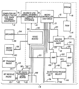
FIGURE 1 is a simplified schematic, in block
zo diagram form, of the preferred embodiment of the present
invention;
FIGURE 2 is a simplified flowchart illustrating the
connection phase provided by the present invention; and
FIGURE 3 is a simplified flowchart illustrating the
data phase provided by the present invention.
Best Mode for Carrv~na Ovr th Inv n ion
Referring to the drawing and to FIGURE 1 in
particular, shown therein and generally designated by
so the reference character 120, is a preferred embodiment
of a modem-controller according to the present
invention. Microcontroller 10 is a microprocessor which
is employed as the controller for modem-controller 120.
21 ~3~362
One static read-only memory (RAM) 14 is added to the
system to provide adeguate working space for
programming. An erasable programmable read only memory
(EPROM) 16 is added to the system to provide enough ROM
space for the firmware. RAM 14 and EPROM 16 are
operatively connected to microcontroller 10 by data and
address bus 12. Microcontroller 10 executes the
firmware or modem BIOS stored in EFROM 16 and
manipulates the data in RAM 14 through the data and
so address bus I2. A decoder in microcontroller l0 is used
to decode the address bus to select RAM 14, EPROM 16 or
data pump 18. Modem-controller 120 communicates with the
DTE 2 through the RS232C interface 6 operatively
connected to microcontroller I0. In the disclosed
embodiment, DTE 2 is a computer or DTE. Ring indicator
signal is sent to data pump chip 18 via bus 32.
Data pump chip 18 is operatively connected to
microcontroller 10 by data and control bus 20. Data
pump chip 18 is a 2400 baud, full duplex, data pump fax
2o modem device set.
It includes a digital signal processor (DSP) and an
integrated analog (IA) device. In addition to digital
signal processing on the transmitted data, the DSP
provides the interface to microcontroller 10 for
information exchange and controlling. The.IA chip
functions like a digital to analog converter and an
analog to digital converter to manipulate the signal to
and from the DSP.
Modem-controller 120 is able to connect to the
3o normal telephone line 80 through RJ11 jack 116 connected
via bus 115 to data access arrangement (DAA) 64
interface and access, via telephone lines) 80, remote
device 102, such as another modem connected to a
' 2i8b3b2
-11-
computer or other type of DTE or a Fax machine.
Modem-controller 120 establishes the connection through
a dialing process by specific AT commands from the
keyboard of DTE 2. Although most of the applications of
modem transmission involves dial-up lines,
modem-controller I20 can also be connected to a leased
(private) line. Under this condition, special line
conditioning is not needed and the operation is full
duplex over this leased line. In other words, there is
to not any dialing process required before connection to
the leased line. The telephone line ring indication
signal is transferred from the DAA 64 to modem chip 18
via bus 32 while the -OHRELAY, MUTE and -T/D RELAY
signals are transferred to DAA 64 from modem chip 18 via
bus 34.
When an incoming call is present, the ring
indication signal is recognized by the Integrated Analog
(IA) Device of modem chip 18 with appropriate control
signals being sent to DAA 64 by modem chip 18. The
2o assertion of the -OHRELAY signal causes an offhook
(online) function to be performed. The -T/D RELAY
signal controls when telephone line 80 is connected to
RJ11 jacks 116 through bus 115 to DAA 64. MUTE is a
signal,controlled by microcontroller 10 to reduce the
transient effects during offhook and onhook operations
due to the on/off of the relay controlled by the
-OHRELAY signal.
The switching or routing of standard or fax data or
voice to radio frequency telemetry module or packet
3o radio interface 110, DAA 64 to RJ11 jacks 115, or
cellular telephone interface 104. is performed by analog
switches 70, 74, 78 which may be comprised of analog
multiplexer/demultiplexer chips. Analog switch 70 is
21$362
-12-
controlled by the telephone line-select iTL-SEL) signal
from microcontroller 10 via bus 68. Analog switch 74 is
controlled by cellular phone interface-select (CPI-SEL)
signal from microcontroller 10 via bus 72. Analog switch
78 is controlled by RF radio interface select (RFI-SEL)
signal from microcontroller 10 via bus 76.
The auto switching between standard or fax data
mode and voice mode is performed by analog switches 44
which may be comprised of a analog
io multiplexerldemultiplexer chip. Analog switch 44 is
controlled by voice-or-data select (VORD-SEL) signal
from microcontroller 10 via bus 42. This VORD=SEL signal
from microcontroller 10 is controlled by a AT command
suffix, alpha character "v", received from DTE 2 through
15- bus 4, RS232C 6 and bus 8. If a dialing command is
received by the microcontroller and it ends in the alpha
character "v'", a VORD-SEL signal will be sent to analog
switch 44 to select the voice mode.
If a dialing command is received by microcontroller
20 10 and it does not have the alpha character "v" as a
suffix, a VORD-SEL signal will be sent to analog switch
44 to select the standard or fax data mode. If analog
switch 44 is in the standard or fax data select'
position, selected by microcontroller 10 VORD-SEL
2s signal., analog switches 70, 74 and 78 allow the analog
signals transmitted from and received by modem chip 18
to be routed either to RJ11 jacks 115 or cellular phone
interface 104 via bus 36, amplifier 38, bus 40, analog
switch 44, bus 62, analog switch 78, bus 96, DAA 64, and
3o bus 66 or to radio frequency interface 110 via bus 36,
amplifier 38, bus 40, analog switch 44, bus 62, analog
switch 78, bus 98. If analog switch 44 is in the voice
select position, selected by microcontroller 10 VORD-SEL
-13-
signal, analog switches 70, 74 and 78 allow voice
communication transmitted from and received by internal
voice board 52 to be routed either to RJ11 jacks 116,
radio frequency interface 110 and cellular phone
interface 104 via external mike 60, bus 56, external
speaker 58, bus 54, voice board 52, bus 50, amplifier
48, bus 46, analog switch 44, bus 62, analog switch 78,
and either bus 96 to DAA 64, and bus 66'or bus 98 to
radio frequency interface 110.
The present invention also supports another mode of
operation or control. Another type of telephone device
such as an external fax machine can interface via
telephone line 80, RJ1I jacks 116, bus 115, bus 82,
analog switch 88, bus 100 to the cellular phone
interface 104, bus 106, and then bo the cellular
telephone 108 to do wireless external fax transmission
over a cellular telephone system.
This mode is controlled by the microcontroller 10
and if the following conditions exist: A cellular
2o telephone 108 is connected, their corresponding
interface, cellular telephone interface 104 is switched
on, and a telephone device is attached to the RJ11--jacks
116. The switching or routing of the telephone line 80
to the. cellular phone interface 104 is performed by
z5 analog-switches 88 which may be comprised of analog
multiplexer/demultiplexer chips. Analog switch 88 is
controlled by the CPI-SEL signal 72 and LL-SEL signal 68
from microcoiztroller 10 via bus 86.
In summary, different operations can be performed
3o by different settings of the analog switches 44, 7.0, 74,
78, and 88 hence different routing of the signals.
4rhen standard or fax data is being sent from or
received at modem chip 18 on bus 40, the same signals
218b3b2
-14-
are sent to amplifier 48 via bus 122. A mute signal is
also sent to amplifier 48 from microcontroller 10 via
bus 22. Amplifier 48 then outputs a mute signal on bus
50 to voice board 52 to disable speaker 58 during the
transmission and receipt of standard or fax data from or
to modem chip 18.
The cellular telephone 108 connected to
modem-controller 120 is full duplex radio telephone for
use in cellular telephone systems. It consists of an
to internal transmitter and receiver (transceiver) unit,
keypad, display, antenna, mike and speaker.
The cellular telephone provides-full duplex synthesized
FM radio channels for voice and standard or fax data
transmission between the cell site base stations.
The design strategy of.the cellular phone interface
104 is to provide a simulation of a telephone line tip
and ring from a cellular telephone 108 for connection to
DAA 64 of modem-controller 120. In other words, when
cellular mode is selected by microcontroller 10, a
zo interface through DAA 64 to cellular phone interface 104
and then cellular telephone 108 is made and voice and
standard or fax data transmission through cellular
telephone 108 is made like it is a ordinary telephone
line.
2s The 800 MHz radio frequency packet radio 114
connected to modem-controller 120, when interfaced, is a
half-duplex radio with synthesized frequency selection
for operation in the 800 MHz band for transmitting and
receiving and provides 3 watts of output power. Using
3o two 800 MHz radio frequency packet radio modules 114 and
115, connected to modem-controller 120, full duplex
operation is achieved.
2186362
-15-
The 800 MHz radio frequency telemetry module 114
connected to modem-controller 120, when interfaced,
contains both a data transmitter and a data receiver
(transceiver). It has manual or user programmable
s synthesized frequency selection for half-duplex
operation on a single channel in the 806 - 824 MHz
receive and 851 - 869 MHz transmit frequency range. The
transmitter power output is 1-watts at 7.2 volts. It
uses 25 kHz channel spacing. Using two 800 MHz radio
1o frequency telemetry modules 114 and 115, connected to
modem-controller 120, full duplex operation is achieved.
The 450 MHz radio frequency telemetry module 114
connected to modem-controller 120, when interfaced,
contains both a data transmitter and a data. receiver
1s (transceiver). It has synthesized frequency selection
for half-duplex operation on a single channel in the 450
- 480 MHz or 403 - 430 MHz transmit frequency range. The
transmitter power output is 2 watts at 7.2 volts. It
uses 25 kHz or optional 12.5 kHz minimum channel
zo spacing. Using two 450 MHz radio frequency telemetry
modules 114-and 115, connected ~o modem-controller 120,
full duplex operation is achieved.
The design strategy of the radio frequency
interface 110 is to provide an interface and the logic
2s required by radio frequency 450 MHz or 800 MHz telemetry
modules) 1I4 and 115 or the 800 MHz packet radios 114
and 115 for connection to modem-controller 120. In other
words, when radio frequency mode is selected by
microcontroller 10, a interface through bus 98, RF radio
3o interface/logic board 110, bus 112 and 1I3 and then to
one or two (one for half-duplex operation or two for
full duplex operation) radio frequency telemetry
modules) or packet radios) 114 and 115 are made and
z ~ ~~~~z
-16-
voice and standard or fax data transmission through the
telemetry modules) or packet radios) 114 and 115 is
accomplished.
The RS232C standard defines the interface between
DTE 2 and microcontroller 10 and-modem chip 18. Commands
entered from DTE 2 is sent via RS232C cable 4, RS232C
interface 6, and bus 30 by asynchronous transmission
into serial port, bus 8 to microcontroller 10.
Modem-controller 120 contains a high performance
l0 2400/9600 baud data pump that supports 9600 baud fax and
2400 baud standard data speeds and is designed such
that it can be used for standard data or fax data
transmission and receiving with ordinary telephone
lines, radio frequency (RF), satellite systems and
Zs cellular systems. Unlike conventional modems, it does-
not provide any hardware jumpers or switch settings and
thus eliminates the inconvenience of hardware jumpers or
switch settings for ease of .operation to non-technical
users. Instead, the alteration of all functional
2o features can be thoroughly accessed through AT commands
and settings of S registers through communication
software.
Modem-controller 120 is a Hayes compatible modem,
including most of the AT commands implemented in Hayes
25 Smartmodem except those commands for synchronous
transmission and speaker control. In order to increase
the efficiency, full-duplex operation is supported
during communication. Modem-controller 120 can establish
connection with various speeds such as 300 baud, 600
3o baud, 1200 baud, 2400 baud, 4800 baud (fax), 9600 baud
(fax) under different communication protocols. Retrain
sequence is automatically detected and sent to maintain
proper communication environment between calling and
21~b362
answering modem during connection. Auto answer mode is
activated by setting up the ring count value before
connection.
Modem-controller 120 can establish the connection
in either-originate mode or answer mode directly
selected by the software. Pulse and tone dialing are
both supported in modem-controller 120 with software
selection of the pulse and tone dialing format.
One of the unique features of modem-controller 120
1o is the capability of connection with a cellular
telephone 108, satellite system radio, or a radio
frequency telemetry module or packet radio 114. This-
enhances it's portability when installed in hand held,
portable or. lap-top computers or DTE (DTE). In addition
is to standard data or fax data transmission, '
modem-controller 120 provides the function for voice
communication. Together with voice board 52, the user
can establish voice conversation in a hands-free mode
whether connected to telephone lines 80, satellite
2o systems, radio frequency networks and cellular telephone
systems 108.
In order to eliminate standard or fax data errors
that may occur during signal quality deterioration,
interference or noise, hand-off, and loss of carrier
25 using dirty or poor quality conventional voice telephone
lines, radio frequency networks, satellite systems, and
cellular telephone systems, the ITC-RM was developed.
The ITC-RM enhances and fine tunes Mt~P levels 2, 3, 4
and 5. ITC-RM is programmed in the modem BIOS or
3o finmvare in an EPROM 16 for modem-controller 120.
In the present invention, modem-controller 120 can
be connected to a cellular telephone 108, satellite
system, or a radio frequency telemetry module or packet
~ ~ ~~3~~~
-is-
radio 114. Carrier loss happens more frequently in
wireless systems than in a ordinary telephone lines. The
modem-controller, using ITC-RM, adapts to the unhealthy
working environment of wireless systems by increasing
the re-try count from two to six in the link phase. The
link-up is first initiated at 2400 BAUD. If a 2400 BAUD
link-up fails, the modem-controller, using the ITC
Reliable Mode (ITC-RM), will down-shift to 1200 BAUD.
After successful connection, the modem-controller, using
1o the ITC Reliable Mode (ITC-RM), will set the packet
re-try count to eighteen. During carrier loss, the
modem-controller, using the ITC-AM, will temporarily
suspend standard and fax data transmission to wait for
the. recovery of the carrier. If the carrier loss occurs
in synchronous mode, the modem-controller, using the
ITC-RM, will switch back to asynchronous mode until
detection of the carrier occurs and will then switch
back to synchronous mode. In other words, even if the
carrier is lost, the modem-controller will not "hang
up" .
With reference to the software implementation, the
operation of modem-controller-120 is divided into three -
modes comprising a command mode, a data (standard or
fax) mode and an escape mode; therefore, the software is
based upon the three modes of operation.
In the command mode, modem-controller 120 receives
the input via the serial port through the RS232C
interface 6. If the echo command is on (ATE1), the same
character which is input will be fed back to the DTE 2.
3o Modem-controller 120 accepts the standard AT
command set prefix 'AT' or 'A/' to repeat last command.
If the input character is 'A', modem-controller 120 will
wait for the typing of 'T' or '/'. If not received,
216362
-19-
modem-controller 120 will repeat the process for the
next 'A'. After receiving a correct command prefix
'AT', modem-controller 120 will start to accept typing
as AT command and will store them in the command buffer
s until a carriage return is entered. Modem-controller
120 will then process the commands in the command buffer
and output corresponding messages to the DTE 2 via the
serial port. If an incorrect command is sent, an error
message will be displayed. On the other hand,
1o modem-controller 120 will not wait for the input of a
carriage return if 'A' is captured first. Instead, it
will repeat the last entered command in the command
buffer.
One.of.the smart features in the command mode is
is the capability of auto baud rate checking and auto
format adjustment. This is established by the
inspection of the AT command prefix 'AT' and 'A/'. At
this stage, the reception of the prefix is done on bit
manipulation instead of accepting the whole character
2o through the serial port.of the microcontroller 10. The
start bit duration of the typed character is measured
and hence the current communication baud rate is
determined. According to the measured baud rate, the
succeeding bits will be sampled and captured, also the
25 input character is then fund. If this is a character
'A', then the next character is captured in the same
manner except that the duration of its start bit need
not be measured again. If the next character is 'T' or
'/', the process of auto baud rate check will then be
3o completed.
The format of asynchronous communication protocol
(parity bit, data bit, stop bit) is also determined
during the capture of the command prefix. This is
21~63~Z
-20-
achieved by the sampling of bit 8 and bit 9 of the
character 'A' and valid character 'T' or '/'. From the
different combination of these bits, specific format of -
protocol is recognized. Afterward, the serial
communication that follows will employ the serial port
of the microcontroller 10 since the baud rate and format
have been decided.
If there is an incoming call, the ring signal (ring
indication) will be detected and a 'RING' message will
1o be shown for each ring.
If the number of rings received is equal to the
value stored in the SO register or the 'ATA' command is
entered, modem-controller 120 will connect the line to
answer the coming call. It will then switch to standard
1s or fax data mode for transmission. '
To initiate a standard data call, the command 'ATD'
is entered and then followed by the dialed number.
Modem-controller 120 will check for the presence of a
dial tone and then for a busy tone after completing the
2o dialing process. At the end of the dialing process,
modem-controller 120 will wait for the presence of the
carrier within the time specified by the value in S7
register. If a carrier is detected and connection is
successful, standard data mode is entered. Othenaise the
as call process is aborted.
To initiate a fax data call, a specialized fax
software is employed that lets you simply enter a phone
number to dial, be it stored or manual, and press a key
to dial. All AT commands are in the background and not
3o entered by the user. Modem-controller 120 will check for
the presence of a dial tone and then for a busy tone
after completing the dialing process. At the end of the
dialing process, modem-controller 120 will wait for the
2186362
-21-
presence of the carrier within the time specified by the
value in S7 register set by the specialized fax
software. If a carrier is detected, connection is
successful, fax data mode is entered. Otherwise the
s call process is aborted.
To initiate a voice call, the command 'ATD~ is
entered, followed by the dialed number and the suffix
'v'. Modem-controller 120 will check for the presence of
a dial tone and then for a busy tone after completing
to the dialing process. At the end of the dialing process,
modem-controller 120 will wait for the calling party to
answer and on answering, voice mode is entered.
Otherwise the call process is aborted. The carrier tone
is disabled in the voice mode.
15 Because modem-controller 120 employs ITC-RM, which
enhances and fine tunes MNP levels 2, 3, 4 and 5 to
eliminate standard data errors that may occur using
dirty or poor quality conventional voice telephone
lines, radio frequency networks, satellite systems and
2o cellular telephone systems, there are two absolutely
different modes (normal mode and the MNP) with ITC-RM
selectable by the user. For the application of
interfacing with a cellular telephone 108, satellite
system 118, and the radio frequency telemetry module or
25 packet radio 114 and 115, the enhanced MNP mode using
ITC-RM is compulsory for maintaining proper operation
due to the noisy environment and frequently lost
carrier. The mode switching is automatically set to this
compulsory setting of enhanced MNP mode using iTC-RM if
3o either the radio frequency interface or cellular
telephone interface is switched on or manually
controlled by a set of particular AT commands (&E0, &E1,
-22- -
&E2) using communication software for landline and
satellite system use.
In the normal mode and without activation of the
enhanced MNP mode with ITC-RM, modem-controller 120
handles the data transmission as a conventional modem.
It follows the CCITT or BELL recommendation to perform
asynchronous transmission at 300, 600, 1200 or 2400
baud. The data flowing between the modems is on a
character basis. No error detection and data compression
to is done using this mode.
In the MNP with ITC-RM, transmission is performed
in units of data packets. The technique of handshaking
is added to normal data transmission in order to achieve
error elimination and protocol compatibility. There are
differen~.packets named Link Protocol Data Unit (LPDU)
defined in MNP for specific purposes.
Each LPDU has its own information such as the
sequence number and series number and a C~~clical
Redundancy Check (CRC) checksum at the end of each LPDU.
2o During the connection phase, information exchange
between the calling and called party rely on the
transmission of LR LPDU and Link Acknowledgement packet
(LA LPDU). Through this three way handshaking, a
compromised operating environment will be established
for both modem devices. Asynchronous transmission works
on these packets. If MNP level three or above can be
achieved after the Link phase, then synchronous mode
will be selected for data transmission in SDLC frame
structure with a view to the increase in efficiency.
3o Otherwise, asynchronous mode will be kept unchanged as
usual.
The error detection is done by comparing the
calculated CRC with the actual CRC which is received for
-as-
each packet. If errors occurs, an acknowledgement
requesting the retransmission of the had packets will be
issued. Hence the enhanced MNP with ITC-RM can achieve
excellent reliability for data communication over
s cellular telephone systems and radio frequency networks.
A retransmission counter defines the maximum available
attempts for retransmission. An inactivity timer keeps
tract of the silence time (no information exchange)
after the line is connected. If the above time
l0 limitation is violated, the transmission will be
terminated at once thereby indicating that the current
working environment is abnormal and hence the line
should be disconnected.
In normal operation, the data packets will be sent
is in order by the sender modem according to their sequence
number specified during transmission. For a successful
receipt of a data packet (LD LPDU), the receiver must
issue the positive acknowledgment to the sender to
indicate the correct receipt of the packet. This is
2o accomplished by placing the sequence number of the data
packet in the LA LPDU packet. In order to alleviate the
overhead caused by the frequently transmitted LA packet,
the receive modem does not need to make an immediate
response to each data packet received. Instead, it
2s permits the delay of the transmission of LA packets
within the extent of the window size (four data packets
in the inventive protocol). The receive modem will send
the sequence number of the latest good data packet
received. As a result, a1I of the packets with sequence
3o numbers earlier than that in the LA packet which is
acknowledged are positively acknowledged by only one
transmission of the LA packet.
i
2186362
-24-
If modem-controller 120 is operating in the escape
mode, all the AT commands can be used. The typing of
the escape sequence '+++' in the data mode will switch
the modem-controller 120 to the escape mode for the
access of AT commands. On the contrary, the command
'ATO' will bring the modem-controller back to the data
(online) mode once again, -
With reference to FIGURE 2, the connection phase of
the inventive protocol software, prior to the..
to transmission of data, is disclosed.
The line, either telephone line, radio frequency,
infrared, satellite system or cellular, is connected
(line is connected 128) between the local and remote
modem either through the dialing process or a
leased-line operation. Desired communication '
configuration (establish desired communication 130) is
established with a remote modem through handshaking.
The presence of the carrier from the remote modem
(carrier present 132) is determined.- If the carrier is
not present within a specified time (times up 136) then
the connection will be terminated (terminate the
connection 134) and the connection phase must be
initiated again. If the carrier is not present and the
specified time has not elapsed, then the-presence of the
as carrier from the remote modem (carrier. present 132) will
continue until the specified time has elapsed or the
presence of the carrier occurs. With the carrier being
present, the remote modem is interrogated (interrogate
the remote modem 138) by sending appropriate
link-connect packet to the remote modem.
If the correct link-connect packet 140 is received
from the remote modem then the MNP with the ITC-RM
connection is successful 142 and the next step is (go to
-25-
data phase 144) as shown in FIGURE 3. If the correct
link-connect packet 140 is not received, then the
correct link-connect packet 140 is repeated through the
Retry-Count 146 step until successful receipt of the
s correct link-connect packet is received or until the
Retry-Count = 6 step 148 eguals the count of six. At
that time, the MNP with ITC-RM connection fails 150 and
a line disconnect 152 or-the connection phase is run in
the non-MNP mode and ITC-RM.
1o With reference to FIGURE 3, the data phase of the
inventive protocol software, after the successful
connection phase, is disclosed. From data phase 144,
the presence of the carrier (carrier present 158) is
determined. If the carrier is present, then the
15 determination is made as to the readiness of a data
packet (data-packet is ready 160) for transmission. If
the carrier is not present, then the modem is switched
to the asynchronous mode (switch to asynchronous mode
162) and the presence of the carrier_(carrier present
20 164) is determined. Upon the presence of a carrier,
modem-controller 10 is switched to the synchronous mode
(switch to synchronous mode 166) and the determination
is made as to the readiness of a data packet-(data
packet_is ready 160). Upon dete~nination that a data
25 packet is ready for transmission then the data packet is
transmitted (transmit this data packet 168) and
acknowledgement is noted (positive acknowledgement
received 170). If positive acknowledgement received 170
occurs, then the cycle is back to step 158, step 160,
3o step 168 to step 170. This cycle is repeated until
transmission is complete or carrier islost. If
positive acknowledgement is not received at step 170,
then a check is made to determine if the retransmission
-zs-
timer elapsed 172 has occurred. If it has, then the next
step is to the (ReTx - count =-ReTx - count + 1) 174 to
the step of (ReTx - count = 18) 176. If the ReTx count
has not reached 18, then the cycle is back to step 168
where the data packet is transmitted again until the
ReTx - count = 18. At that time, the MNP with ITC-RM
disconnect sequence 178 disconnects the modem from the
telephone line, cellular phone or radio frequency
telemetry module or packet radio. Such a disconnect
sequence, is of the kind that is well known in the art.
If the retransmission timer elapsed 172 has not
occurred, then a check is made for a negative
acknowledgement received 180. If a negative
acknowledgement 180 has been received, then the next
step is step 174 and eventually back to step 16$
(transmit this data packet). If a negative
acknowledgement has not been received, thenthe cycle is
back to step 170 (positive acknowledgement received 170)
to determine if a positive acknowledgement has been
2o received.
whenever a positive acknowledgement_is received at
step 170, that yes status is sent back to step 158 to
check for a carrier present 158 so another data packet
may be, made ready for transmission as in step 160.
When a data packet is received 182, then an
acknowledgement (acknowledge the remote modem 184) is
noted and the cycle is back to step 158 to start the
sequence to send another data packet. If a packet is
not received (acknowledge the reuiote modem 184), then
3o the cycle is back to step 158.
In one arrangement, remote device 102 can be
replaced by an infrared transceiver. Such an
arrangement can be used on several computers within
-27-
infrared range of each other to form a network. The
area over which the network can operate can be expanded
by elevating an infrared relay device.
Although the present invention has been described
herein with reference to specific forms thereof, it is
evidexit that many alternatives, modifications and
variations will become apparent to those skilled in the
art in light of the foregoing disclosure. Accordingly,
this description is to be construed as illustrative only
1o and is for the purpose of teaching those skilled in the
art the manner of-carrying out the invention. It is to
be understood that the-forms of the invention herewith
shown and described are to be taken as presently
preferred embodiments. Various changes may be made in
the shape; size and arrangement of parts. For example,
equivalent elements may be substituted for those
illustrated and described herein, parts may be reversed,
and certain features of the invention may be utilized
independently of other features of the invention. It
2o will be appreciated that various modifications,
alternatives, variations, etc., may be made without
departing from the spirit and scope of the invention as
defined by the appended claims.