Note: Descriptions are shown in the official language in which they were submitted.
Betts 59-2-19 218~ ~ S
.~
F,chs ~Ancelin.~ Mf~thod ~rd .~pparAt~ for Dat-A Over Ce~ r
Cro~ r to l~ qt~ t; ).~
Related subject matter is disclosed in the co-pending commonly assigned, U.S.
Patent qrFlil~qtilmr~ of: Betts et al., entitled "Echo Canceling Method and Apparatus for
5 Data Over Cellular," serial No. XXXX, filed on September X, 1995; Bet~ts et al., entitled
"Echo Canceler Gam Tracker for Cellular Modems," serial No. XXXX, filed on
September X, 1995; and Flanagan et al., entitled "Cascade Echo Canceler ,~n~n~ement,"
serial No. XXXX, filed on September X, 1995.
~q,~ 'Of''-ll
The present invention relates to data ~ n.~ equipment, e.g., modems,
and, more ~u~icul~ly, to echo-canceling modems.
Today, the North American cellular system is lu~t;dulllil~Lcly an analog system
sometimes referred to as AMPS (Advanced Mobile Phone Service). The Cullc*/ulldiulg
cellular e ~mmllni~tionc channel is sometimes referred to as am "impaired channel" since
15 it is affected by a number of charmel ;",~ like Rayleigh fading, co-channel
iulLclr~ ~ciu~ c~ etc., that increase the error rate and, thus, degrade the overall l)~' rl." " .,...~ of
the mobile connection. This is in contrast to a lamd-line .~.,..,..".;. ,~1;onc cha~nel, where
the predominant i ~ is additive white gaussian noise (AWGN). Those in the art
have realized that one way to improve data IIAII~ III rates in the cellular CUVilUlUllCllL
20 is to use a data protocol that is better suited to combating the effects of the cellular
~IIVilUlllUlCUL over the cellular portion of the data connection. One example of a cellular-
oriented protocol is the "Enhanced Throughput Cellular" (ETC) protocol, developed by
AT&T Paradyne.
Nevertheless, even with a cellular-oriented protocol, ;,,,l"~;""~ in the cellular
25 char~nel continue to limit the effective data rate over the cellular channel. For example,
reliable, i.e., consistent, data 1l,.ll~.ll;~;llll over 9600 bits per second (bps) is difficult to
maintain.
S of ~l ^ T
Notwithstanding the above-mentioned ;~ i"". ,l~ present in the cellular
30 channel, we have discovered a non-linearity in the cellular AMPS net~vork that has been
effecting the ability to reliably maintain cellular data rates over 9600 bps. In particular,
when a cellular modem is performing training with a far-end PSTN modem, the cellular
AMPS network distorts a far-end echo signal that is used by the cellular modem to train
~ettssg~ 9 21~6~0~
its echo carlceler. We estimate that this distortion of the far-end echo signal occurs in
a~ a~ely 40% of the AMPS cellular illfla~uu~,~ul~. The source of the distortion of
the far-end echo signal is due to a non-linear compander in some base-station radios and
the half-duplex approach that modems use to train echo c~mcelers. The result is that the
S echo canceler of the cellular modem is not properly trained thereby causing a residual
echo signal to exist. This residual echo signal limits the maximum cellular data rate to
9600 bps (often, this cellular data rate is reduced to 7200 bps.) Without this residual echo
sign~l, the cellular modem and PSTN modem could often achieve a data rate of 14,400
bps (and even higher in the future).
Therefore, and m accordance with the invention, we have developed a method and
apparatus for reducing the residual echo signal, which is effectively caused by the above-
mentioned distortion of the far-end echo signal during training. In particular, during the
above-mentioned half-duplex training phase a far-end modem does not remam silent but,
instead, transmits a pilot tone to the near-end modem during the time that the near-end is
15 training its echo canceler. This pilot tone is of a high enough signal level to cause the
above-mentioned compander to achieve its linear range. As a result, this invention
eliminates the incorrect training caused by the distortion of the far-end echo signal,
thereby providing the ability to }eliably maintain cellular data rates greater than 9600 bps.
In an embodiment of the invention, the PSTN modem tr~msmits a "pilot tone"
20 during the time that the cellular modem is training its echo canceler. This pilot tone is of
a high enough signal level to cause the compander to achieve its linear range. The
cellular modem is modified to notch, or filter, out this pilot tone from the received signal.
The filtered received signal is then used by the cellular modem to train its echo canceler.
Since the above-mentioned compander is now in the same linear range that it will be in
25 when the both modems go into full-duplex mode, the echo canceler is properly trained to
the far-echo signal. Residual echo is thus eliminated and the modem can achieve its
highest data rate.
Brief I~cl~ription of ~L^ Drawi~
FIG. 1 is a block diagram of a mobile data ci"."~"l,.;. ~I;~nc system embodying
30 the principles of the invention;
FIG. 2 shows an illustrative portion of a training sequence;
FIG. 3 is a flow diagram of an illustrative method for use in an originating modem
in accordance with the principles of the invention;
FIG. 4 is a flow diagram of an illustrative method for use in an answering modemin accordance with ~e principles of the invention; 2
~ BetLc59-2-19 218640S
FIG. 5 shows an illustrative portion of a training sequence as modified by the
inventive concept;
FIG. 6 is an illustrative block diagram of a portion of cellular modem 100 of FIG.
I embodying the principles of the invention;
FIG. 7 is an illustrative block diagrarn of a portion of PSTN modem 300 of FIG. I
embodying the principles of the invention; and
FIGs. 8 - 10 show the inventive concept when the cellular modem is the
"answering" modem.
D~
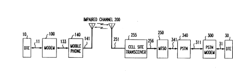
Other than t_e mventive concept, the elements of FIG. 1 function as m the prior
art and will not be described in detail. FIG. I shows a block diagram of a mobile data
c." ", l .. " .;. .~l ;nne system that includes cellular modem 100, which embodies the inventive
concept. As shown, cellular modem 100 is coupled to mobile phone 140 for L~a~ ~iLLil~g
data signals to, and receiving data signals from, PSTN modem 300 via cell site
transceiver 255, impaired channel 200, Mobile Te~ linnc Switching Office
(MTSO) 250, and PSTN 340. Both cellular modem 100 and PSTN modem 300 are also
coupled to respective data terminal equipment (DTE) 10 and 30.
Before descIibing the inventive concept, the following is a brief overview of the
operation of the mobile data 1,. ,.. " .. , ;. ~ 1 ;nn.C system of FIG. 1 once a data cormection is
20 PCtAhlichPcl~ i.e., after training has been completed. A data signal is applied to cellular
modem 100, via line 11, from DTE 10 for l.. ~ ;.. to PSTN modem 300. Line 11
represents the signaling, electronics, and wiring, for conforming to a DTE/DCE (data
l:...."."..,;~.AIinnc equipment) interface standard lilce EIA RS-232. Cellular modem 100
modulates this data signal as is known in the art to, typically, a quadrature amplitude
modulated (QAM) signal, which is provided via line 133 to mobile phone 140. Although
not necessary to the inventive concept, it is assumed for the purposes of this example that
the modem signal is compatible with TntPrnAtinnAI TPJr;~..l..l~l,l;~ ~1i.",.~ Union (lTTJ)
standard V.32bis. Mobile phone 140 further modulates this trAncmiccion signal onto a
predefined cellular carrier to provide a cellular data signal to antenna 141. Cell site
transceiver 255 receives the cellular data signal via antenna 251 and provides a received
modem signal to T.~TSO 250 for trAncmiccinn via public-switched-telephone network
340, to a far-end data endpoint as represented by PSTN modem 300 and DTE 30.
Ideally, the data signal received by DTE 30 from PSTN modem 300 is identical to the
data signal provided by DTE l O to cellular modem l OO. T,, ,~ l of data signals in
the opposite direction, i.e., from DTE 30 to DTE 10 occurs m a ~e fashion.
.` 218~'qO5
Betts 59-2-19
However, before r~ g a data connection, modems, as known in the art,
perform a standard sequence of signaling that is also referred to as hand-shaking or
training. This signaling determines such parameters as data rate, modulation to use, and
trains, or sets, what is knov~n in the art as filter tap coefficient values for filters like echo-
S cancelers and equalizers, which combat ill,c.rclcu~.c and distortion effects caused by theCulllluul~ aLiOllS channel. As known in the art, the training sequence for an echo canceler
is performed half-duplex. Full-duplex training of the echo canceler, while theoretically
possible, is not practical from a p~ ,/p~lru~ viewpoint in the design of data
~uullllulli~ Lions equipment.
Since different data ~uu~ Lions standards like ITU V.32bis and ITU V.34
have different training sequences, a generalized representation of a training sequence
comprising a number of phases is illustrated in FIG. 2. It is assumed tfiat cellular modem
100 is the calling modem and that PSTN modem 300 is the answering modem. As shown
in FIG. 2, the training sequence is irlitially full-duplex during phase "A." The latter is
followed by a phase "B," which is half-duplex and is additionally divided into two
portions: "B1" and "B2". In portion "Bl," of phase "B," the called modem, PSTN
modem 300, sends a signal to train the echo canceler of PSTN modem 300 while thecellular modem 100 is silent. Then, in portion "B2," of phase "B," the calling modem,
cellular modem 100, sends a sigmal to train the echo canceler of cellular modem 100
whi~e the far-end PSTN modem is silent. To complete the description of FIG. 2, after
half-duplex training phase "B," both modems enter a subsequent full-duplex training
phase "C," which is then followed by a "DATA" phase in ~vhich data is actually
~rlmmlmir~trd between the two modems.
During the respective half-duplex training portions of phase "B," each modem
uses the returned far-end echo signal to adjust the tap coeff1cients of its echo canceler.
The far-end echo signal is a result of subsequent 4-wire to 2-wire signal conversion
within the PSTN, as is known in the art (It should be noted that other CO111~JUI~CIIL~; are
also adjusted during training, e.g., equalizer ro~ff~ ntc~ etc. However, for the purposes
of this example, only the echo camceler training is described.)
In the cellular network, the base station radio - cell site transceiver 255 - performs
audio processing. One of the audio processmg stages is a compander (not shown). The
compander is linear over a given signal range. UurulLu l~cly, we have discovered that
some r.,.,ll","rl ,~ are not linear in the signal range of the returned far-end echo signal
during the half-duplex training phase. As a result, this non-linearity of the compander
results in: training the echo canceler of the cellular modem to a distorted far-end echo
si~al. However, when the cellular modem ~ul~ Lucll~ly goes into full duplex mode, i.e,
~ BettsS9-2-19 21864n~
both l l r~ g a signal to, and receiving a signal from, the PSTN modem, the received
signal level passing through cell site transceiver 255 causes the compander to operate in
its linear range. This change in compander operation results in a gain change in the echo
path that causes a ~Pvr~ nn in echo canceler ~ ro""~ resulting in a large "residual
5 echo" in the cellular modem. In other words, there is a loss of echo r~nvrll~tinn This
residual echo signal limits the maximum cellular data rate to 9600 bps (often, this cellular
data rate is reduced to 7200 bps.) Without this residual echo signal, the ce~lular modem
and PSTN modem could often achieve a data rate of 14,400 bps (and even higher in the
future).
This problem can be solved by modems with a four-wire interface at the PSTN-
side of the cellular data connection. For example, a cellular network that includes a
cellular modem pool, as well as "mu-law" modem pools being instaUed at customer
locations solve this problem. Unfortunately, a large number of cellular users will still be
calling 2-v~ire PSTN modems for the foreseeable future. In addition, this problem could
15 be solved by allowing contirlued adaptation of the echo canceler during data L~
However, this adaptation process can be slow. Indeed, the above-mentioned co-pending
patent application of Flanagan et al. provides a solution to quickly adapt the co~ffiri~nic
of am echo canceler after half-duplex training. ulLr~liuul..t~,ly, some modems (as
;llL~d by cellular modem 100) only adapt during the training sequence to conserve
20 hardware lCiUULI~;lLl~ i, such as memory, and thereby reduce the cost of the data
~:IJIIIIII~III;. '.1;l~ll~ equipment.
Therefore, and in accordance with the invention, we have developed a method amd
apparatus for reducing the residual echo signal, which is effectively caused by the above-
mentioned switching between a linear mode of operation and a nonlinear modem of
25 operation of a network cornpander. In palticular, during the above-mentioned half-duplex
training phase a PSTN modem does not remain silent but, instead, trarlsmits a pilot tone
to the cellular modem during the time that the cellular modem is training its echo
canceler. This pilot tone is of a high enough signal level to cause the above-mentioned
compander to achieve its linear range. As a result, this invention eliminates the incorrect
30 training caused by the distortion of the far-end echo signal, thereby providing the ability
to reliably maintain cellular data rates greater than 9600 bps.
In order to facilitate 11~ of the inventive concept reference should now
be made to FIGs. 3 and 4, which represent an illustrative methods for use in an
originating modem and answering modem, I~ ,liYel~. For the purposes of this
35 description, cellular modem 100 is illustratively the originating modem and PSIN
~ Betts 59-r2-l9 218 6 ~ ~ ~
modem 300 is illustratively the answering modem. For simplicity, the steps of dialing (in
cellular modem 100), and answering(by PSTN modem 300), are not shown.
First, attention should be directed to FIG. 3. In step 705, cellular modem 100
enters training, e.g., Ic~ cl~Liivc phase "A," shown in FIG. 2. Following trainmg phase
"A," cellular modem 100 enters half-duplex training phase "B" in step 710. In this phase,
cellular modem 100 is silent during portion "Bl," as represented by step 715. After
portion "B 1," cellular modem 100 moves to phase "B2" to train its own echo camceler. In
accordance with the inventive concept, during phase "B2" cellular modem 100 first filters
the received signal in step 720 to remove a pilot tone transmitted by far-end PSTN
modem 300 (described below). Then, cellular modem 100 trains its echo camcelers on the
filtered received signal in step 725. After half-duplex training portion "B2," cellular
modem 100 enters full-duplex training phase "C" in step 730. After completion oftraining phase "C," cellular modem 100 enters the "DATA" phase in step 735.
Turning now to ~IG. 4, ,ullc~u~ldillg steps are illustrated for PSTN modem 300,the answering modem. In step 805, PSTN modem 300 enters training, e.g., Ic,Ulcsc~ ivc
phase "A," shown in FIG. 2. Following training phase "A," PSTN modem 300 enters
half-duplex training phase "B" in step 810. In portion "B1," PSTN modem 300 trains its
own echo canceler in step 815. After portion "B1," PSTN modem enters phase "B2."However, in phase "B2" PSTN modem 300 is not silent, as in the prio} art. Instead,
PSTN modem 300 transmits a pilot tone to cellular modem 100 in step 820. For
example, this pilot tone could illustratively be at a frequency of 300 Hz, at -20dBm, for
the duration of the half-duplex training phase "B2." After half-duplex training portion
"B2," PSTN modem 300 ~1:c~ ;.".~ ",;~ ,.. of the pilot tone and enters full-
duplex training phase "C" in step 825. After completion of training phase "C," cellular
modem 100 enters the "DATA" phase irl step 830.
The effect of the methods shown in FIGs. 3 and 4 on the IC~lC~llLdLiVC trainmg
sequence is shown in FIG. 5. In particular, training phase "B2," is no longer halduplex
but full-duplex. However, to avoid the above-mention cl-mrl~ involved with full-duplex training of an echo canceler, cellular modem 100 filters out the pilot tone from the
received signal before training its echo canceler. As a result of the above, if the
compander (not shown) of cell site transceiver 255 has the aboYe-mentioned non-
linearity, then the ~ of the pilot tone by PSTN modem 300 moves the
compander into its linear range of operation. Tbis results in the proper training of the
echo c~mceler in cellular modem 100 so that once full-duplex tr~n~mi~cil~n begins there is
no gain change in the echo path.
~ BettsS9-~-19 2186~0~
Illustrative embodiments of the invention are shown in FlGs. 6 and 7 for cellular
modem 100 and PSTN modem 300, lc~e~ ,ly. ~xcept for the inventive concept, the
operation of the various CU~ iS well-known.
As shown in FIG. 6, a binary input data sequence ~xbl is provided by DTE 10 to
S cellular modem 100 on line 11. This input data sequence is processed by transmitter 605
to form a near-end transmitted signal, nsf~). Illustratively, near-end transmitted signal,
ns(t~, represents a quadrature amplitude modulated (QAM) signal. The near-end
transmitted signal, ns(t), is provided by hybrid 610 to mobile phone 140, via line 133. (It
should be noted that during training, the binary input sequence is generated by cellular
10 modem 100 as in known in the art. For simplicity, this alternate source of the binary data
sequence is not shown.)
Transmitter 605 is umder the control of CPU and memory 630, which is a micro-
processor based central processing unit and associated memory for storing program data.
It is assumed that transmitter 605 includes an encoder, shaping filter, digital to analog
IS converter, etc., for processing and modulating the input data sequence on line 11 to
provide tbe QAM signal, ns(t), on line 606. As part of this processing of the input data
sequence, transmitter 605 represents the input data sequence as a sequence of complex-
valued symbols ~a"~, at nominal rate 1/~ symbols per second. (This processing may also
include scrambling, ~Cdlllldall~)/ and other forms of encoding.) As can be seen from FIG.
20 3, this input data sequence is also used by far echo canceler 650 (described below). For
simplicity, the local echo canceler is not shown.
Tuming now to the other direction of . .""".,1.,; .,.l;.,.~ an analog line signal,fs(t),
transmitted from a far-end modem, e.g., PSTN modem 300, is received by hybrid 610 and
is directed to bandpass filter (BPF) 620. This signal is referred to as the "far-end data
25 signal," and utilizes the same frequency band as the transmitted signal, ns(t), i.e., cellular
modem 100 is a full-duplex modem. Bandpass filter 620 removes energy outside thesignal passband from the far-end data signal, which is then converted to digital form by
amalog-to-digital (A/D) converter 625 to form received signal rs¢t).
The signal, fs~t), reaching the input of bandpass filter 620 is corrupted by so-
30 called echo signals. Echo signals are typically introduced at each four-to-two wire
conversion m the, . " "" ,l .,.;~,, l lonC system.
The far-end echo signal comprises transmit signal energy from cellular modem
100 which was transmitted towards PSTN modem 300 in the frrst instance but was
reflected back to cellular modem 100 as a result of, for example, an impedance mismatch
35 at a two-~-four wire conversion within PSTN 340. The received signal, rs(t), provided
~ls6~n~
~, Betts 59-2-19
by A/D conYerter 625, thus contains not only energy from the far-end data signaltransmitted by PSTN modem 300, but also energy from the far-end echo signal.
In accordance with the principles of the invention, the received signal, rsft), is
applied to switch 640. The latter is under the control of the central processmg unit of
S CPU and memory 630. During training phase "B2," the received signal, rs(t), includes
the above-described pilot tone. Therefore, in the above-mentioned step 720 of FIG. 3, the
central processing unit of CPU and memory 630 causes the received signal, rs(t), to be
applied to notch filter 615 via sviitch 640. Notch filtèr 615 is a simple notch filter as
known in the art and is designed to remove the above-described pilot tone from the
received signal, rs(t). As a result, far echo canceler 650 does not receive the pilot tone
and trains on only the far-echo signal present in the received signal, rs(t). After training
far echo canceler 650, the central processing unit of CPU and memory 630 controls
switch 640, in step 725 of FIG. 3, to remove notch filter 615 from the received signal
path and applies received signal rs(t) directly to far echo canceler 650.
Turning now to FIG. 7, an illustrative block diagram of PSTN modem 300
embodying the principles of the invention is shown. A binary input data sequence ~Xb~ is
provided by DTE 30 to PSTN modem 300 on line 31. This input data sequence is
processed by transmitter 305 to form a near-end transmitted signal, r~s(t). Illustratively,
near-end transmitted signal, ns(t), represents a quadrature amplitude modulated (QAM)
signal. The near-end transmitted signal, ns(t), is provided by hybrid 310 to PSTN 340,
via line 311. (It should be noted that during training, the binary input sequence is
generated by PSTN modem 300 as in known in the art. For simplicity, this alternate
source of the binary data sequence is not shown.)
Transrnitter 305 is umder the control of CPU and memory 330, which is a micro-
processor based central processing unit and associated memory for storing program data.
It is assumed that transmitter 305 includes an encoder, shaping filter, digital to analog
converter, etc., for processmg and modulating the input data sequence on line 31 to
provide the QAM signal, ns(t), on line 306. As part of this processing of the input data
sequence, transmitter 305 represents the input data sequence as a sequence of complex-
valued symbols ~, at nomirlal rate 1/1 symbols per second. (This processimg may also
include sl~r~3mhlin~, redundancy and other forms of encoding.)
In accordance with the principles of the invention, PSTN modem 300 includes a
means for generating the above-mentioned pilot tone, i.e., pilot tone generator 315 and
switch 370. During trairling phase "B2," PSTN modem 300 transmits this pilot tone to
cellular modem 100. In particular, during the above-mentioned step ~20, the central
processing unit of CPU and memory 330 controls switch 370, via line 382, to apply the
~ BettsS9-2-19 ~18~5
pilot tone for trAnqmiqCi~n to cellular modem 100. After training phase "B2" has ended,
the central processing unit of CPU and memory 330 controls switch 370 to apply the
output signal from transmitter 305 to hybrid 310. As a result, PSTN modem 300 is not
silent during the half-duplex portion of the traiming signal as in the prior art.
It should be noted that although an illustrative switch is shown in FIGs. 6 and 7
for the purposes of description, those in the art would realize that m~1ifi~Ationq to
corresponding algorithms in a digital signal processor (not shown) would be equivalent.
For example, in FIG. 7 transmitter 305 represent~C a digital signal processor that is
prograrnmed to provide ~,ull~ol~ lg 1~".1~1, .1.;"~ signaling. As a result, to implement
this inventive concept, transmitter 305 is simply ~c~ lcd to generate the above-mentioned pilot tone during training phase "B2." Further, it should be noted that
although the invention was described in the context of a called, or answering, modem
providing the pilot tone, the mventive concept also applies to a calling, or originating,
modem providing the pilot tone to the answering modem, which now filters out the pilot
I S tone to train its echo canceler. This case is illustrated in FIGs. 8 - 10.
The foregoing merely illustrates the principles of the invention and it will thus be
appreciated that those skilled in the art will be able to devise numerous alternative
~lall~C~ L~ which, although not explicitly described herein, embody the principles of
the invention and are within itc spirit and scope.
For example, although the invention is illustrated herein as being i",~
with discrete functional building blocks, e.g., an echo canceler, etc., the functions of any
one or more of those building blocks can be carried out using one or more appropriate
programmed processors, e.g., a digital signal processor.
In addition, although the inventive concept was described in the context of a
cellular data connection this invention is applicable to the PSTN network. Also, although
the invention was described m the context of using a pilot tone, other signals can be used
so long as the signal causes the above-mentioned compander to enter the linear range of
operation and the receiver can d~ LL~ly cancel this signal before training its echo
canceler. Those skilled in the art would realize that although shown in the context of a
hybrid, some cellular modems have a four-wire interface to the cellular transceiver. In
addition, it should be realized that the above-described inventive concept could be
selectively enabled by a ucer via u e of the well-known "AT-command set."